
Subscribe to Our Youtube Channel
Related Manuals for iSMA CONTROLLI iSMA-B-MAC36NL


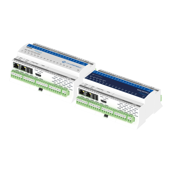
Summary of Contents for iSMA CONTROLLI iSMA-B-MAC36NL
- Page 1 iSMA-B-MAC36PRO User Manual Installation and Start-up Guide www.ismacontrolli.com DMP257en | 1st Issue rev. 10 | 11/2023...
-
Page 2: Table Of Contents
MAC36 Controllers User Manual Table of Contents Introduction ........................... 4 Revision History..........................4 Key Features ..........................4 Safety Rules..........................6 Technical Specification ......................7 Software License Notice ....................10 Hardware Specification .....................11 Dimensions ..........................11 Terminals and Internal Connection Diagram...............11 Power Supply..........................12 5.3.1 Earth Grounding ........................ - Page 3 MAC36 Controllers User Manual Restore Controller to the Default State ................28 6.8.1 Default State .......................... 28 Restore Controller to the Factory Default ................29 6.9.1 Factory Default ........................29 6.10 Data Recovery Service .......................31 6.10.1 Data Recovery Service Editor..................... 32 6.10.2 Blocks Configuration......................
-
Page 4: Introduction
UI, 8 AO, 4 DI, and 8 DO allows to employ the devices in different applications. MAC36 controllers provide control, data logging, alarming, scheduling, integration, and visualization. The range of MAC36 controllers consists of: • iSMA-B-MAC36NL; • iSMA-B-MAC36PRO. 1.1 Revision History Rev. - Page 5 MAC36 Controllers User Manual • real-time programming; • 2 Fast Ethernet (independent); • 1 RS485 (opto-isolated), optional extension as second RS485 port; • optional M-Bus extension; • 2 USB (1 OTG, 1 host); • 16 UI, 8 AO, 4 DI, and 8 DO; •...
-
Page 6: Safety Rules
MAC36 Controllers User Manual 2 Safety Rules • Improper wiring of the product can damage it and lead to other hazards. Make sure that the product has been correctly wired before turning the power on. • Before wiring or removing/mounting the product, make sure to turn the power off. Failure to do so might cause an electric shock. -
Page 7: Technical Specification
MAC36 Controllers User Manual 3 Technical Specification iSMA-B-MAC36NL iSMA-B-MAC36PRO Power Supply Voltage 24 V AC/DC ± 20% isolated Power consumption 14 W at 24 V DC; 24 VA at 24 V AC Universal Inputs Temperature input • Measurement with attached RTDS •... - Page 8 MAC36 Controllers User Manual Resistive load 3 A at 230 V AC/30 V DC RS485 Interface RS485 Up to 128 devices (base and Half-duplex, opto-isolated optional) Communication Modbus RTU/ ASCII, BACnet MS/TP protocols Baud rate From 2400 to 115200 Address 1 to 247 M-Bus Interface Voltage...
- Page 9 MAC36 Controllers User Manual Length 160 mm/6.3 in Height 62 mm/2.45 in Table 2. Technical specification www.ismacontrolli.com DMP257en | 1st Issue rev. 10 | 11/2023 page 9 of 44...
-
Page 10: Software License Notice
MAC36 Controllers User Manual 4 Software License Notice This product contains the code covered by the GNU General Public License (GPL). Note: This product contains open source software code, the Intellectual Property Rights to which are the property of The Qt Company Ltd. with its registered office at Bertel Jungin aukio D3A, 02600 Espoo, Finland. -
Page 11: Hardware Specification
MAC36 Controllers User Manual 5 Hardware Specification This section outlines the hardware specification of MAC36 controllers. 5.1 Dimensions Figure 2. Dimensions 5.2 Terminals and Internal Connection Diagram MAC36 controllers are supplied by 24 V AC/DC. The power supply block is separated. The grounding pin located next to power supply terminals must be connected to the ground. -
Page 12: Power Supply
MAC36 Controllers User Manual 5.3 Power Supply The device is designed to work with 24 V AC/DC separated power supply. Figure 4. Power supply connection 5.3.1 Earth Grounding Earth grounding protects from electrostatic discharge or other forms of EMI. Connecting the controller’s ground spade lug to nearby earth ground is possible in hardware versions below 2.1. -
Page 13: Rs485 Network Termination And Biasing
In case of an RS485 twisted pair cable, the termination is typically 120 Ω. In the iSMA-B-MAC36NL and iSMA-B-MAC36PRO versions, there is a built-in 3-position switch on the back side of the device (access after removing the back cover), which is dedicated to connecting termination resistor and/or biasing resistors. - Page 14 MAC36 Controllers User Manual Figure 7. RS485 network termination and biasing If the switch is in the BIA position, it connects the biasing resistors 680 Ω (pull-down to ground SG and pull-up to +5 V DC) to the RS485 bus. The biasing is added to the RS485 bus in order to reduce communication failures.
-
Page 15: M-Bus Connection
MAC36 Controllers User Manual 5.5 M-Bus Connection 5.5.1 About M-Bus The M-Bus (Meter Bus) was developed to fill the need for a system for the networking and remote reading of utility meters, for example, to measure the consumption of gas or water in the house. -
Page 16: Connection
MAC36 Controllers User Manual 5.5.4 Connection M-Bus devices can be connected directly only to the iSMA-B-MAC36NL-M and iSMA-B- MAC36PRO-M, the controller’s hardware version with the M-Bus interface (max. 20 devices). Figure 10. The M-Bus connection 5.6 LED Indicators The device is equipped with LEDs for quick status checking and diagnostics: Figure 11. -
Page 17: Mini Usb
MAC36 Controllers User Manual long as the device sends/receives packages, the communication LEDs blink continuously. • The universal inputs LEDs (U1-U16) indicate the statuses of the universal inputs. If the LED is on, the resistance value connected to the input is lower than the switching threshold value (dry contact input is active). -
Page 18: Start-Up
MAC36 Controllers User Manual 6 Start-up 6.1 Before the Start To be able to operate normally, the device needs to have: its SD card fitted in SD card box, and its license assigned. The hardware itself is only the base for the SD card, which consists of all the software parts necessary for hardware management. -
Page 19: Factory Settings
Password: Niagara Out of the box, the controller has no default station installed. Note: Starting from the iSMA-B-MAC36NL hardware version 2.1, the passphrase is saved on the SD card. Once the Niagara Framework is upgraded to 4.8 version, the passphrase www.ismacontrolli.com... -
Page 20: First Login
MAC36 Controllers User Manual is reset to “niagara”; therefore, the station will not restart automatically, and it is required to re-enter the passphrase and manually restart the station. Figure 15. Passphrase reset Figure 16. Passphrase reset 6.4 First Login 6.4.1 First Login to the Controller Platform in Workplace Warning! It is highly advisable to install the Data Recovery Service with the first commissioning of the controller. - Page 21 MAC36 Controllers User Manual Password: type in the factory default password (niagara); • Click the OK button to accept all settings. Figure 17. First login view If the Change Platform Defaults Wizard displays, click Next to step through creating a system passphrase, creating a new platform account, and removing the default platform account, as shown below.
-
Page 22: Tcp/Ip Configuration
MAC36 Controllers User Manual Figure 19. First login view Figure 20. First login view Click Finish to complete these changes. The system completes making the connection between the host and Workbench, and displays the Nav Container View. 6.5 TCP/IP Configuration 6.5.1 TCP/IP Settings A TCP/IP Configuration is one of several platform views. - Page 23 MAC36 Controllers User Manual Configuring TCP/IP communication settings is a task for the systems integrator, while initially setting up a controller. Perform the following steps: • Open a connection to the platform. • Expand the Platform container in the Navigation tree, and double-click the TCP/IP Configuration container.
- Page 24 MAC36 Controllers User Manual Figure 23. TCP/IP host setting These available host fields are as follows: • Host Name: synonymous with “computer name,” this is a string that can be processed by a DNS server to resolve to an IP address. On Windows-based systems, this hostname is the computer’s identification in its workgroup or domain.
-
Page 25: Connection To The Console
MAC36 Controllers User Manual • IPv6 Gateway: the IPv6 address for the router that forwards packets to other IPv6 networks or subnets. • DNSv6 Servers: the IPv6 address for one or more IPv6 DNS servers (if available), where each can automate associations between host names and IPv6 addresses. Included are icon-buttons to Add (enter the IP address of the server), Delete, and move Up/ Down (set the DNS search order). -
Page 26: Controller System Update
6.7 Controller System Update 6.7.1 Preparations for Updating If the iSMA CONTROLLI releases an update of one or more components of the controller system (OS, NEL, JVM, modules), such update may be performed remotely, using a distribution file without physically accessing the SD card. -
Page 27: Installing The Update
MAC36 Controllers User Manual The package contains elements of the system that will be updated as new elements of the system, or as newer versions of Niagara, operating system, modules, and the Clean dist file. After unpacking, run the bat file. Figure 28. -
Page 28: Restore Controller To The Default State
MAC36 Controllers User Manual Passing through the next wizard windows, an additional dialog window will appear, informing about the need to update the appropriate controller system component (OS, NEL, JVM). Figure 30. Commissioning Wizard with tab informing about the needs to update Note: No additional dialog window in the Commissioning Wizard means that the controller has the current version of the system component, and there is no need before an update–... -
Page 29: Restore Controller To The Factory Default
MAC36 Controllers User Manual data is deleted from the file system, including station bog files, Px files, modules, etc. The unit’s TLS private key information is also deleted. In addition, installing a clean dist deletes all configured platform users, restoring the factory-default platform credentials and port (3011). - Page 30 MAC36 Controllers User Manual Figure 32. Top cover After removing the cover, there are two DIP switches and two rotary switches. Looking at the description on the right, there is an information about the function of the switch 6 in the S3 DIP switch.
-
Page 31: Data Recovery Service
MAC36 Controllers User Manual Note: If the factory default procedure is performed, the station cannot be recovered from the controller. 6.10 Data Recovery Service The Data Recovery Service is the station platform service that provides an NV-RAM support for MAC36 controllers. Providing the platDataRecovery module is installed, this service automatically appears under Platform Services. -
Page 32: Data Recovery Service Editor
MAC36 Controllers User Manual • Amount of free flash memory space. Figure 34. Data Recovery Service Editor in PlatformServices of the MAC36 controller The figure above shows the default view for the service: the Data Recovery Service Editor. Note: The example above reflects a scenario, where a station saving has occurred at least once since the service was created. -
Page 33: Blocks Configuration
MAC36 Controllers User Manual • Station Save Limit: the number of station saving operations that are allowed to occur during the Station Save Limit Period, before it is determined that the station is spending too much time saving. Exceeding the limit throws the Data Recovery Service into the fault status, since too much data is being generated. -
Page 34: Data Recovery Service Properties
MAC36 Controllers User Manual free space, along with numerical values. By default, the currently active NV-RAM block is expanded, showing a bar graph of current buffer usage. Above the bar graph of each block, its Status is described, typically as either: Active, Idle, or Flushing, with other states Purging, Awaiting Idle, Flush Queued, Defragmenting, Reserved, Fail, and Unknown. -
Page 35: Hdmi Connection
A). The HDMI connection allows viewing the user’s station data directly on the display, without a need of connecting PC with a web browser. It is recommended to use the HMI panels from the iSMA CONTROLLI offer–other panels may not work or www.ismacontrolli.com DMP257en | 1st Issue rev. -
Page 36: Preparation For Hmi
Preparation for using the HMI panel: • Download the update from the iSMA CONTROLLI support site, which allows to support HMI views via HDMI port, and is necessary to install the required files and modules for the appropriate version of Niagara. -
Page 37: Module Isma_Hdmi
MAC36 Controllers User Manual The iSMA_HDMI module is not installed by default on the MAC36 platform. It needs to be installed during the commissioning or by using the Software Manager tool under the platform component. The iSMA_HDMI module has been created to service, configure and maintain the HDMI connection in MAC36. - Page 38 MAC36 Controllers User Manual • Screensaver mode: the panel displays the image chosen by the user. Turning back from this mode to the Normal mode is executed right after the user’s activity (touch). The last open site is displayed. • Standby mode: the panel is in an energy-saving mode, the backlight is switched off.
- Page 39 MAC36 Controllers User Manual Figure 40. Screensaver • Standby Enabled: this slot switches on or switches off the Standby mode (true–mode enabled, false–mode disabled). By default, the Standby mode is active. • Standby Time: this slot contains the time value in hh:mm:ss format. This time starts counting down, when there is no user activity on the display (no touch).
-
Page 40: Adding And Start-Up Of The Hdmi Service
MAC36 Controllers User Manual • Auto Login Credentials: username and password for the station user. If the Auto Login is enabled, the user with the credentials stored in this slot will be logged in to the station. • Auto Login Time: this slot contains the time value in hh:mm:ss format. This time allows to decide to log in another user than the one that has been configured for the Auto Login function. - Page 41 MAC36 Controllers User Manual Note: Connecting the panel to the HDMI port, while the power supply is connected, makes it not detectable by the controller. • During the start-up of the controller (platform/station), and provided the HDMI service is not configured in the running station, the following image will be visible: Figure 42.
-
Page 42: User Fonts Support
MAC36 Controllers User Manual Figure 44. Start page In case of unexpected problems with establishing a connection or suspension of the view page, or, for example, the need to quickly return to the start page, there is a special service menu available. To access it, swipe from the top of the screen and the following service menu view becomes accessible on the top of the screen. - Page 43 MAC36 Controllers User Manual • Courier New [Liberation Mono]; • Tahoma [Wine Tahoma]; • Times New Roman [Liberation Serif]; • PT Sans [implemented directly]; • Source Sans Pro [implemented directly]; • Inconsolata [implemented directly]; • Hunkyfonts Sans [implemented directly]; • Ubuntu-font-family [implemented directly];...
- Page 44 MAC36 Controllers User Manual Figure 47. Transferring fonts Upon a successful transfer, a „Transfer complete” window pops up. Once all the user fonts are successfully transferred, go to the Application Director and reboot the controller (restart of the station is not enough). After the controller is rebooted and the station loaded, the HDMI panel will properly depict text with user-uploaded fonts.
Need help?
Do you have a question about the iSMA-B-MAC36NL and is the answer not in the manual?
Questions and answers