
Subscribe to Our Youtube Channel
Related Manuals for iSMA CONTROLLI iSMA-B-FCU


Summary of Contents for iSMA CONTROLLI iSMA-B-FCU
- Page 1 User Manual Hardware www.ismacontrolli.com DMP242en | 1st Issue rev. 3 | 02/2022...
-
Page 2: Table Of Contents
Hardware User Manual Table of Contents Introduction ..........................3 Revision History..........................3 Safety Rules..........................4 Technical Specification ......................5 Hardware Specification ......................8 Dimensions ............................8 Power Supply............................8 4.2.1 24 V AC Power Supply for External Equipment..............9 Terminals and Internal Connections...................9 4.3.1... -
Page 3: Introduction
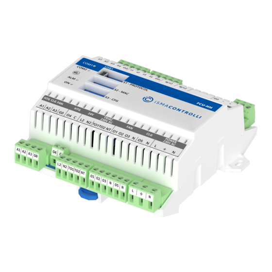
Hardware User Manual 1 Introduction The iSMA-B-FCU is a fully programmable controller, built with the aim of controlling the FCU. The controller is factory-equipped with the two most popular open communication protocols Modbus ASCII/RTU and BACnet MS/TP, which are selected using DIP switches. -
Page 4: Safety Rules
Hardware User Manual 2 Safety Rules • Improper wiring of the product can damage it and lead to other hazards. Make sure that the product has been correctly wired before turning the power on. • Before wiring or removing/mounting the product, make sure to turn the power off. -
Page 5: Technical Specification
Hardware User Manual 3 Technical Specification iSMA-B-FCU-HH iSMA-B-FCU-HL iSMA-B-FCU- Power Voltage 230 V AC ± 10% 24 V AC ± 10% Supply Power Consumption Max. 12 VA (including 7 VA for triac outputs) Special Temperature Input Measurement with attached RTDs Inputs Resolution ±0.1°C... - Page 6 Hardware User Manual Triac Load Min.: 20 mA Min.: 20 mA Min.: 20 mA Outputs Max.: 0.5 A at 230 V Max.: 0.3 A at 24 V Max.: 0.5 A at 24 V AC = 0.3 A = I...
- Page 7 Hardware User Manual Dimensions Width 123 mm Length 137 mm Height 55 mm Table 3. Technical specification www.ismacontrolli.com DMP242en | 1st Issue rev. 3 | 02/2022 page 7 of 53...
-
Page 8: Hardware Specification
Figure 1. Dimensions 4.2 Power Supply The iSMA-B-FCU-HH and iSMA-B-FCU-HL versions are designed to work with the 230 V AC power supply. Each iSMA-B-FCU device is equipped with a built-in 6 A fuse protecting the controller and the connected 230 V AC equipment. www.ismacontrolli.com DMP242en | 1st Issue rev. -
Page 9: Ac Power Supply For External Equipment
4.2.1 24 V AC Power Supply for External Equipment The iSMA-B-FCU-HH is equipped with a 24 V AC, 7 VA power supply output to supply an external equipment like sensors and actuators. This power supply uses a separate coil in the transformer. -
Page 10: Isma-B-Fcu-Hh
Figure 4. iSMA-B-FCU-HH diagram of terminals and internal connections 4.3.2 iSMA-B-FCU-HL The iSMA-B-FCU-HL hardware version has a high voltage power supply (230 V AC) and low voltage triac outputs (24 V AC). The triac outputs are connected to a built-in 24 V AC transformer, as shown in the diagram below. -
Page 11: Isma-B-Fcu-Ll
Figure 5. iSMA-B-FCU-HL diagram of terminals and internal connections 4.3.3 iSMA-B-FCU-LL The iSMA-B-FCU-LL hardware version has a low voltage power supply and triac outputs (24 V AC). The triac outputs are connected to power supply terminals. The maximum current for each of the triac outputs is 0,5 A. The maximum power used by the external equipment connected to the 24 V terminals (L2, N2) cannot exceed 7 VA in total. -
Page 12: Rs485 Communication
Hardware User Manual Figure 6. iSMA-B-FCU-LL diagram of terminals and internal connections 4.4 RS485 Communication 4.4.1 Connecting RS485 Communication Bus Figure 7. RS485 connection www.ismacontrolli.com DMP242en | 1st Issue rev. 3 | 02/2022 page 12 of 53... -
Page 13: Rs485 Grounding And Shielding
Hardware User Manual 4.4.2 RS485 Grounding and Shielding In most cases controllers are installed in enclosures along with other devices, which generate electromagnetic radiation (for example, relays, contactors, transformers, motor invertors, etc.). Such electromagnetic radiation can induce electrical noise into both power and signal lines, as well as direct radiation into the controller, causing negative effects on the system. -
Page 14: Front Panel And Dip Switches
If the controller is powered up by a USB, all inputs and outputs are operational (except for triac outputs, which require external power supply). 4.6.2 LED The iSMA-B-FCU device is equipped with 4 LED diodes for quick status check and diagnostics: •... -
Page 15: Dip Switch
If the device remains in the bootloader status, the power LED (ON) and the communication LED (COM1) blink alternatively. The communication LED keeps its functionality and blinks also after sending/receiving data packages. 4.6.3 DIP Switch The iSMA-B-FCU controller is equipped with 3 DIP switches: • 6-position S1 - PROTOCOL DIP switch; •... - Page 16 Hardware User Manual Protocol Off (0) Off (0) Modbus RTU Off (0) On (1) Modbus ASCII On (1) Off (0) BACnet Master On (1) On (1) BACnet Slave Table 5. Setting protocol WARNING! In BACnet mode, switch number 4 must be in ON(1) position, and switch number 5 decides if BACnet works in master or slave mode (please check on the above table). ...
- Page 17 S3 CFG DIP Switch The iSMA-B-FCU device has the 8-position DIP switch, which can be used in client application. Each of 8 positions can have true or false state. This DIP switch is dedicated for setting configuration in client application.
-
Page 18: Default Settings
I1-I4 digital input counters Table 8. Default values 4.7.1 Restoring Default Settings To restore the default iSMA-B-FCU device settings, follow the steps below: Step 1: Turn power supply off Step 2: Set section 6 of Protocol switch to ON Step 3: Turn on power supply, power LED blinking Step 4: Switch section 6 of Protocol switch to OFF to restore the default settings. -
Page 19: Inputs And Outputs
Hardware User Manual 5 Inputs and Outputs 5.1 Inputs The iSMA-B-FCU device is equipped with two types of inputs: 4 digital inputs (for Boolean values) and 4 special inputs (for resistance and voltage measurement). 5.1.1 Special Inputs The iSMA-B-FCU device has 4 built-in special inputs, which can work in the following modes: •... - Page 20 Hardware User Manual Figure 14. Special inputs in analog mode connection Special Input in Resistance Mode In this mode, the special input measures resistance value with the voltage driver. The input works in range from 0 to 1000 kΩ (1 MΩ), with resolution ±20 Ω for 20 kΩ load.
-
Page 21: Digital Inputs
EEPROM memory. WARNING! If the default settings are restored, the value of the counter is set to 0. 5.2 Outputs The iSMA-B-FCU device is equipped with three types of outputs: 2 triac outputs, 5 digital outputs, and 4 analog outputs. www.ismacontrolli.com DMP242en | 1st Issue rev. -
Page 22: Triac Outputs
The iSMA-B-FCU device is equipped with two triac outputs designed for heating and cooling thermal valve actuators. Depending on controller model, triac outputs can be connected to actuators with 230 V AC supply (for iSMA-B-FCU-HH) or to actuators with 24 V AC supply (for iSMA-B-FCU-HL and iSMA-B-FCU-LL). In the iSMA-B-FCU-HL version, triac outputs are supplied with 24 V AC from a build-in transformer, whereas in iSMA-B-FCU-LL and iSMA-B-FCU-HH triac outputs are connected directly to power supply terminals. -
Page 23: Digital Outputs
24VOut 5.2.2 Digital Outputs All digital outputs are based on relays, which can operate with 230 V AC voltage (in iSMA- B-FCU-LL, digital outputs are working with 24 V AC). The iSMA-B-FCU device has 2 types of digital outputs: •... - Page 24 Figure 20. O1-O3 digital outputs, examples of conenctions O4 HTG Relay The iSMA-B-FCU device is equipped with relay output, which in the FCU application is dedicated to an external heater. This relay is separated from the rest of the control circuit.
- Page 25 Figure 21. Example of an electrical heater connection O5 CLG Relay The iSMA-B-FCU device is equipped with a relay output, which in the FCU application is dedicated to an external cooler. This relay output is internally connected to the power supply, therefore there is no need to connect external supply.
-
Page 26: Analog Outputs
Hardware User Manual Figure 23. O5 digital output, example of 24 V AC electrical cooler connection (iSMA-B-FCU-LL) 5.2.3 Analog Outputs The iSMA-B-FCU device is equipped with 3 analog outputs 0-10 V DC. These outputs are designed for controlling the following actuators: •... - Page 27 Hardware User Manual Figure 25. Analog outputs, example of connecting 0-10 V analog fan control www.ismacontrolli.com DMP242en | 1st Issue rev. 3 | 02/2022 page 27 of 53...
-
Page 28: List Of Supported Temperature Sensors
Hardware User Manual 6 List of Supported Temperature Sensors • 10K3A1 • 10K4A1 • • 20K6A1 • 2.2K3A1 • 3K3A1 • 30K6A1 • SIE1 • TAC1 • SAT1 Sensor 10K3A1 β coefficient 3975K Manufacturers Cylon, Honeywell, Johnson, Satchwell, Seachange °C... - Page 29 Hardware User Manual 8056 6530 5325 4367 3601 2985 2487 2082 1751 1480 1256 1070 Sensor 10K4A1 β coefficient 3695K Manufacturers Andover, Delta Controls, Siebe, York °C Ω 330749 www.ismacontrolli.com DMP242en | 1st Issue rev. 3 | 02/2022 page 29 of 53...
- Page 30 Hardware User Manual 239831 181532 135233 105081 78930 61030 47549 37316 29490 23462 18787 15136 12268 10000 8197 6754 5594 4656 3893 3271 2760 2339 1990 1700 1458 1255 www.ismacontrolli.com DMP242en | 1st Issue rev. 3 | 02/2022 page 30 of 53...
- Page 31 Hardware User Manual 1084 Sensor β coefficient 3435K Manufacturers Carel °C Ω –40 188500 144100 –30 111300 86430 –20 67770 –15 53410 –10 42470 –5 33900 27280 22050 17960 14690 www.ismacontrolli.com DMP242en | 1st Issue rev. 3 | 02/2022...
- Page 32 Hardware User Manual 12090 10000 8313 6940 5827 4912 4161 3536 3020 2588 2228 1924 1668 1451 1266 1108 Sensor 20K6A1 β coefficient 4262K www.ismacontrolli.com DMP242en | 1st Issue rev. 3 | 02/2022 page 32 of 53...
- Page 33 Hardware User Manual Manufacturers Honeywell °C Ω –40 806800 574400 –30 413400 300400 –20 220600 –15 163480 –10 122260 –5 92220 70140 53780 41540 32340 25340 20000 15886 12698 10212 8260 6718 5494 4518 3732 3098 2586 www.ismacontrolli.com DMP242en | 1st Issue rev. 3 | 02/2022...
- Page 34 Hardware User Manual 2166 1823 1541 1308 1114 2.2K3A1 Sensor β coefficient 3975K Manufacturers Ambiflex, Johnson °C Ω –50 154464 –40 77081 –30 40330 –20 22032 –15 –10 12519 –5 9529 www.ismacontrolli.com DMP242en | 1st Issue rev. 3 | 02/2022...
- Page 35 Hardware User Manual 7373 5719 4487 3539 2814 2252 1814 1471 1199 www.ismacontrolli.com DMP242en | 1st Issue rev. 3 | 02/2022 page 35 of 53...
- Page 36 Hardware User Manual Sensor 3K3A1 β coefficient 3975K Manufacturers Alerton °C Ω –50 200348 150524 –40 100701 76853 –30 53005 41048 –20 29092 –15 21868 –10 16589 –5 12694 9795 7619 5971 4714 3748 3000 2417 1959 1598 1310 1080 www.ismacontrolli.com...
- Page 37 Hardware User Manual Sensor 30K6A1 β coefficient 4262K Manufacturers Drayton °C Ω –30 622911 477393 –20 331876 –15 245785 –10 183697 –5 138502 www.ismacontrolli.com DMP242en | 1st Issue rev. 3 | 02/2022 page 37 of 53...
- Page 38 Hardware User Manual 105305 60713 62347 48511 38019 30000 23828 19046 15317 12390 10079 8243 6777 5600 4650 3879 3251 2737 2313 1963 1672 1430 1228 1058 www.ismacontrolli.com DMP242en | 1st Issue rev. 3 | 02/2022 page 38 of 53...
- Page 39 Hardware User Manual Sensor SIE1 Manufacturers Barber Colman, Siebe °C Ω –50 10732 10624 –40 10517 10344 –30 10172 9913 –20 9654 –15 9320 –10 8933 –5 8496 8044 7489 6938 6370 5798 5238 4696 4185 3707 3271 2875...
- Page 40 Hardware User Manual 1929 1685 1472 1287 1127 Sensor TAC1 β coefficient 3500K Manufacturers °C Ω –40 39024 29358 –30 22284 17073 –20 13192 –15 10276 –10 8068 www.ismacontrolli.com DMP242en | 1st Issue rev. 3 | 02/2022 page 40 of 53...
- Page 41 Hardware User Manual –5 6382 5085 4078 3294 2676 2188 1800 1488 1237 1034 www.ismacontrolli.com DMP242en | 1st Issue rev. 3 | 02/2022 page 41 of 53...
- Page 42 Hardware User Manual Sensor SAT1 Manufacturers Satchwell °C Ω 9652 –40 9584 9467 –30 9349 9159 –20 8968 –15 8708 –10 8396 –5 8031 7614 7150 6649 6121 5580 5039 4513 4012 3545 3117 2730 www.ismacontrolli.com DMP242en | 1st Issue rev. 3 | 02/2022...
- Page 43 Hardware User Manual 2386 2082 1816 1585 1385 1213 1064 www.ismacontrolli.com DMP242en | 1st Issue rev. 3 | 02/2022 page 43 of 53...
-
Page 44: Mac Dip Switch Addressing Table
Hardware User Manual 7 MAC DIP Switch Addressing Table Address www.ismacontrolli.com DMP242en | 1st Issue rev. 3 | 02/2022 page 44 of 53... - Page 45 Hardware User Manual www.ismacontrolli.com DMP242en | 1st Issue rev. 3 | 02/2022 page 45 of 53...
- Page 46 Hardware User Manual www.ismacontrolli.com DMP242en | 1st Issue rev. 3 | 02/2022 page 46 of 53...
- Page 47 Hardware User Manual www.ismacontrolli.com DMP242en | 1st Issue rev. 3 | 02/2022 page 47 of 53...
- Page 48 Hardware User Manual BACnet WARNING! Addressing in the range below will run devices in BACnet slave mode www.ismacontrolli.com DMP242en | 1st Issue rev. 3 | 02/2022 page 48 of 53...
- Page 49 Hardware User Manual www.ismacontrolli.com DMP242en | 1st Issue rev. 3 | 02/2022 page 49 of 53...
- Page 50 Hardware User Manual www.ismacontrolli.com DMP242en | 1st Issue rev. 3 | 02/2022 page 50 of 53...
- Page 51 Hardware User Manual www.ismacontrolli.com DMP242en | 1st Issue rev. 3 | 02/2022 page 51 of 53...
- Page 52 Hardware User Manual www.ismacontrolli.com DMP242en | 1st Issue rev. 3 | 02/2022 page 52 of 53...
- Page 53 Hardware User Manual Table 9. MAC addresses www.ismacontrolli.com DMP242en | 1st Issue rev. 3 | 02/2022 page 53 of 53...
Need help?
Do you have a question about the iSMA-B-FCU and is the answer not in the manual?
Questions and answers