
Related Manuals for iSMA CONTROLLI iSMA-B-MAC36NL


Summary of Contents for iSMA CONTROLLI iSMA-B-MAC36NL
- Page 1 User Manual iSMA-B-LIB-GRAPH www.ismacontrolli.com DMP259en | 1st Issue rev. 2 | 05/2022...
-
Page 2: Table Of Contents
User Manual Table of Contents Introduction ........................... 4 Revision History..........................4 iSMA-B-MAC36NL Overview....................... 4 Key Features ..........................4 Software License........................... 4 Equipment Templates ......................6 List of Templates........................... 6 How to Use Templates ........................ 7 2.2.1 AHU/VAV/RTU Templates ..................... 7 FCU Templates .......................... - Page 3 iSMA-B-LIB-GRAPH User Manual 3.7.2 On/Off Components ......................17 Fans..............................18 3.8.1 Alarm Components ......................18 3.8.2 On/Off Components ......................18 Heat Exchange ..........................19 3.9.1 Alarm Components ......................19 3.9.2 On/Off Components ......................19 3.10 Standalone HVAC........................20 3.10.1 Alarm Components ......................20 3.10.2 On/Off Components ......................
-
Page 4: Introduction
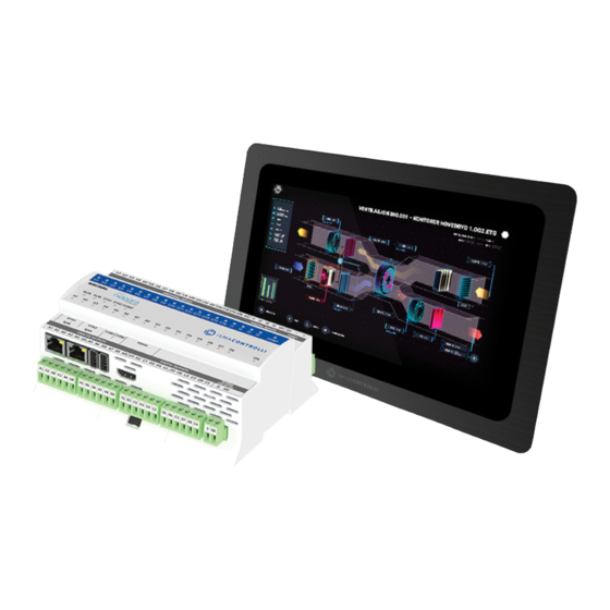
HVAC devices, grids, devices, graphic representations of devices on a floor plan, hydraulic systems with valves, and pumps. The iSMA_Graphics.jar graphics palette is an ideal addition to the iSMA-B-MAC36NL controller set with HDMI port and iSMA-B-PD-10-TB touchpad. 1.1 Revision History Rev. - Page 5 iSMA-B-LIB-GRAPH User Manual Figure 1. No license watermark www.ismacontrolli.com DMP259en | 1st Issue rev. 2 | 05/2022 page 5 of 25...
-
Page 6: Equipment Templates
The iSMA-B-LIB-GRAPH includes graphic templates for various air handling equipment. The graphic templates can be used for visualizations of HVAC applications built in the iSMA-B-MAC36NL and iSMA-B-FCU controllers. The below tables contain a list of specific equipment templates included in the palette. -
Page 7: How To Use Templates
iSMA-B-LIB-GRAPH User Manual FCU_CO2 iSMA-B-FCU controller with iSMA-B-LP-C panel FCU_CO2Humid iSMA-B-FCU controller with iSMA-B-LP-HC panel Table 5. FCU graphic templates included in the palette 2.2 How to Use Templates 2.2.1 AHU/VAV/RTU Templates Each of AHU/VAV/RTU templates has points bound by default. Specific points can be identified in the points folder, which is located under each template (each template has different content in the points folder). -
Page 8: Using Fcu Templates With The Bacnet Protocol
iSMA-B-LIB-GRAPH User Manual Humid or CO2 extension can be used without any iSMA-B-LP panel). If any temperature sensor is connected to any of the S1-S4 special inputs, the graphic FCU template will recognize it and display temperature reading in an appropriate place. Also, the template automatically reads DIP switches states and adjusts to the set configuration. - Page 9 iSMA-B-LIB-GRAPH User Manual Step 3: Right-click the device, expand the Views, and open the iSMA-B-FCU view. The view shows the template graphic with values from connected points. Figure 4. FCU template working in Modbus protocol www.ismacontrolli.com DMP259en | 1st Issue rev. 2 | 05/2022 page 9 of 25...
-
Page 10: Equipment Components
iSMA-B-LIB-GRAPH User Manual 3 Equipment Components The iSMA-B-LIB-GRAPH graphic templates can be expanded by additional components, which are contained in specific folders. Folders with equipment components are described in this section. Please follow a few practical tips while working with graphic templates and additional components: •... -
Page 11: Dampers
iSMA-B-LIB-GRAPH User Manual Figure 6. Effects of Airflow folder components placement For ducts "duct_v", at the bottom of the PX file there should be an object that is first in order in the Widget Tree. 3.2 Dampers Figure 7. Sample graphic components from the Dampers folder The Dampers folder contains dynamic images representing air dampers. -
Page 12: 0-100% Components
iSMA-B-LIB-GRAPH User Manual device. The second value affects the Visibility property, where false causes the graphics to be shown, while true causes the graphics to be hidden (same variable as for the alarm component above). Dragging a Boolean component from the Nav tree to a PX file, selecting "From Palette" in the Make Widget window, and then selecting "From Palette"... -
Page 13: Alarm Components
iSMA-B-LIB-GRAPH User Manual 3.3.1 Alarm Components Components with the "alarm" suffix are dedicated to bind Boolean variables signaling an alarm or failure. Graphics representing the alarm status of the device have been added to these objects. The component has one control value (Value Binding), which impacts the Visibility property. -
Page 14: Heating
iSMA-B-LIB-GRAPH User Manual 3.4 Heating Figure 9. Sample graphic components from the Heating folder The Heating folder contains dynamic images representing air heaters. Due to the features described in section 3, the graphic components in the folder must be arranged in the correct order in the PX file. -
Page 15: Filters
iSMA-B-LIB-GRAPH User Manual 3.5 Filters Figure 10. Sample graphic components from the Filters folder The Filters folder contains dynamic images representing air filters. Due to the features described in section 3, the graphic components in the folder must be arranged in the correct order in the PX file. -
Page 16: Sensors
iSMA-B-LIB-GRAPH User Manual 3.6 Sensors Figure 11. Sample graphic components from the Sensors folder The Sensors folder contains dynamic and static images representing sensors. Due to the features described in section 3, the graphic components in the folder must be arranged in the correct order in the PX file. -
Page 17: Humidifier
iSMA-B-LIB-GRAPH User Manual 3.7 Humidifier Figure 12. Sample graphic components from the Humidifier folder The Humidifier folder contains dynamic images representing air humidifier. Due to the features described in section 3, the graphic components in the folder must be arranged in the correct order in the PX file. -
Page 18: Fans
iSMA-B-LIB-GRAPH User Manual 3.8 Fans Figure 13. Sample graphic components from the Fans folder The Fans folder contains dynamic images representing duct fans. Due to the features described in section 3, the graphic components in the folder must be arranged in the correct order in the PX file. -
Page 19: Heat Exchange
iSMA-B-LIB-GRAPH User Manual 3.9 Heat Exchange Figure 14. Sample graphic components from the Heat Exhange folder The Heat Exchange folder contains dynamic images representing the heat exchangers of air handling units. Due to the features described in section 3, the graphic components in the folder must be arranged in the correct order in the PX file. -
Page 20: Standalone Hvac
iSMA-B-LIB-GRAPH User Manual with the "off-on" suffix automatically pinpoints the dragged component to the control value described as switching between switch-off and switch-on graphics. 3.10 Standalone HVAC Figure 15. Sample graphic components from the Standalone HVAC folder The HVAC Standalone folder contains dynamic images representing stand-alone devices. They include air handling units, blinds/rollers, boilers, chillers, compressors, control units, roof fans, heat exchangers, pumps, radiators, tanks, cooling towers. -
Page 21: 0-100% Components
iSMA-B-LIB-GRAPH User Manual 3.10.3 0-100% Components Components with the "0-100" suffix are dedicated to binding numeric type variables containing analog control value in the range of 0-100%. Graphics have been added to these objects to represent the percentage drive of the device. The component has two control values (Value Binding). -
Page 22: Normal/Alarm Components
iSMA-B-LIB-GRAPH User Manual The Floor Plan folder contains dynamic images representing lighting, sensors, counters, and connectors placed on the floor plan. 3.11.1 Normal/Alarm Components Components with the "normal-alarm" suffix are dedicated to bind Boolean variables indicating normal state or alarm/failure. Graphics representing normal and alarm status of the device have been added to these objects. -
Page 23: Normal/Alarm Components
iSMA-B-LIB-GRAPH User Manual 3.12.2 Normal/Alarm Components Components with the "normal-alarm" suffix are dedicated to bind Boolean variables indicating normal state or alarm/failure. Graphics representing normal and alarm status of the device have been added to these objects. The component has one control value (Value Binding), which causes switching between the graphics of the normal state (false) and the alarm (true) device. -
Page 24: Miscellaneous Components
iSMA-B-LIB-GRAPH User Manual 4 Miscellaneous Components The iSMA-B-LIB-GRAPH palette includes set of miscellaneous components, which are ready to use in visualizations. The components are categorized in the following groups: • background grids; • icons; • widgets; • symbols; • pane. 4.1 Background Grids 4.1.1 Icons The Icons folder includes components representing status icons (cubes) and whole sets... -
Page 25: Faq And Troubleshooting
Software Manager in the platform. Why do graphic components from the 'iSMA_Graphics' palette display the 'Not licensed' watermark? The 'iSMA_Graphics' license is available only for the iSMA-B-MAC36NL controller, and it is its basic compound. Why do 'iSMA_Graphics' components display watermarks on the Supervisor or JACE-8000 controller? The 'iSMA_Graphics' palette is licensed only for iSMA-B-MAC36NL controllers;...
Need help?
Do you have a question about the iSMA-B-MAC36NL and is the answer not in the manual?
Questions and answers