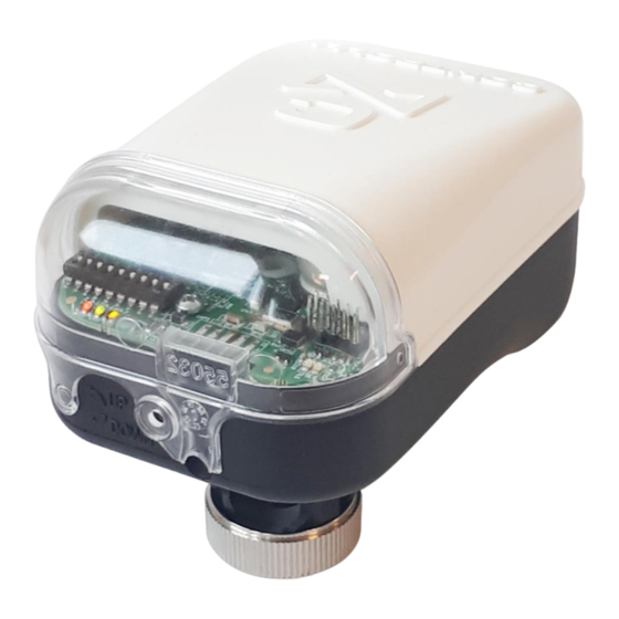
Summary of Contents for iSMA CONTROLLI MVC503R-MB
- Page 1 MVC503R-MB Configuration Tool – Product Manual MVC503R-MB Configuration Tool Product manual Manual of installation and use www.ismacontrolli.com DMP116it | 1 Issue rev. a | 03/2022 pag.
-
Page 2: Table Of Contents
MVC503R-MB Configuration Tool – Product Manual Table of Contents 1 Introduzione ......................3 1.1 Revision History ....................3 1.2 Safety rules ......................3 1.3 Overview ......................3 2 Installation ......................... 3 2.1 Hardware Requirements ..................3 2.2 Configurator Installation Procedure ..............4 2.3 LIBO-USB Serial Converter Installation ............. -
Page 3: Introduzione
3. The products are maintenance free. 1.3 Overview This configuration tool allows to configure and to monitor the MVC503R-MB actuator for correct commissioning of the system. The connection between the computer and the actuator is made via a USB / RS485 converter (LIBO-USB) with a serial communication bus and ModBus protocol (RTU). -
Page 4: Configurator Installation Procedure
To operate in 485 mode it is necessary to set the following DIP-SWITCHES to ON: 1. RS-485 transmission 2. Echo OFF 3. 2-Wire communication For a Modbus connection with MVC503R-MB, the correct terminals to be used are: 1. TDA (-) 2. TDB (+) 3. GND... -
Page 5: User Interface
MVC503R-MB Configuration Tool – Product Manual 3 User Interface 3.1 Main Window When the software is executed, the following window will be displayed: www.ismacontrolli.com DMP116it | 1 Issue rev. a | 03/2022 pag. - Page 6 MVC503R-MB Configuration Tool – Product Manual Figure 1. User interface after the serial converter connection From the “Settings” menu on the top of the window is possible to select: • “Read converter parameters”: read the modbus communication parameters of the converter •...
- Page 7 MVC503R-MB Configuration Tool – Product Manual Figure 4. Configuration File menu From the “Read Device” menu on the top of the window is possible to read all information from the device. Figure 5. Read Device menu From the “Write Device” menu on the top of the window is possible to write the configuration values into the device.
-
Page 8: Modbus Communication
MVC503R-MB Configuration Tool – Product Manual At startup the only selectable Menus are “Language” and “Configuration File”, the “Scan” menu will be enabled once the “CONNECT” button is clicked and if the connection was successful. The available functions of the main window are: •... - Page 9 MVC503R-MB Configuration Tool – Product Manual Figure 10. Windows Control panel to select Device Manager option Select the field “Port (COM e LPT)” and note the serial port number related to the serial converter (in the example below: COM4). www.ismacontrolli.com DMP116it | 1 Issue rev.
- Page 10 MVC503R-MB Configuration Tool – Product Manual Figure 11. Device Manager, select Ports (COM and LPT) option Modbus address of the device (Modbus Address). Modbus address is selectable • via the first 7 dipswitches of the actuator following the encoding into the technical manual (example to select address 1, the dip switch n°1 has to be...
-
Page 11: Modbus Configuration" Box
MVC503R-MB Configuration Tool – Product Manual After press the CONNECT button verify if Modbus Status is OK. The parameters set in the Modbus Configuration box are requested only the first time the software and the Serial converter are used. 3.3 “Modbus Configuration” Box In this box it is possible to set the modbus configuration parameters. -
Page 12: Valve Configuration" Box
MVC503R-MB Configuration Tool – Product Manual Figure 13. Actuator configuration box • Action: it allows to select direct or reverse action • Calibration: it allows to start the stroke calibration of the actuator Press the “READ” button to read the current status, the select from the drop- down menu the label “Learning”... -
Page 13: Actuator Status" Box
MVC503R-MB Configuration Tool – Product Manual Figure 14. Valve configuration box • PICV Valve Type: in case the actuator is installed on a LIBRA pressure independent control valve, it is possible to select the LIBRA range from the drop- down menu in order to improve flow control. - Page 14 MVC503R-MB Configuration Tool – Product Manual Figure 15. Actuator status box shows the information about the actuator status • Status: it shows the current status of the actuator (initial positioning, calibrating, up end stroke, down end stroke, up positioning, down positioning) and the led status on the electronic board.
-
Page 15: Actuator Command" Box
MVC503R-MB Configuration Tool – Product Manual • Low Voltage/Failsafe: it shows the low supply voltage anomaly events as well as the number of emergency return events. • High Voltage: it shows the high supply voltage anomaly events. • Unexpected Stall: it shows the unexpected stall events, that is how many times a stall has occurred inside the range stroke. -
Page 16: Configuration File" Menu
MVC503R-MB Configuration Tool – Product Manual while a value of 120% indicates that the actuator is performing the initial position/calibration. The current feedback value is read by the software at the start-up and cyclically every 1.5sec (it’s possible to read the value clicking on the label “Feedback”). -
Page 17: Scan" Menu
MVC503R-MB Configuration Tool – Product Manual Figure 17. Select the configuration file (Write configuration file option) To upload directly the configuration file parameters to the actuator, select the “Load configuration file” item by selecting the desired configuration file (to perform this operation, a successful connection must be done pressing the “CONNECT”... - Page 18 MVC503R-MB Configuration Tool – Product Manual The table in the left part of the windows can show the main actuator information of a subset of the actuators in the network. The scan can be executed by setting the start Modbus address and the end Modbus address of the actuator group and pressing the “READ”...


Need help?
Do you have a question about the MVC503R-MB and is the answer not in the manual?
Questions and answers