Table of Contents
Advertisement
Quick Links
Advertisement
Table of Contents

Related Manuals for Lumberjack TS254SL


Summary of Contents for Lumberjack TS254SL
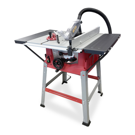
- Page 1 SAFETY AND OPERATING MANUAL 10" Table Saw TS254SL ORIGINAL INSTRUCTIONS TS254SL...
-
Page 2: Product Specification
PRODUCT SPECIFICATION Table Saw TS254SL Motor Power 1800W Table Size 940x640 mm Saw Blade 254X30X48T Cutting Thickness 90° 85mm / 45° 65mm Blade angle 90°~45° Max. Ripping Capacity 645mm Blade Speed 4100 1/min Net Weight 22KG This table saw has been designed for cutting wood and plastic materials. You must not cut metal with this table saw. - Page 3 • The machine must only be used in technically perfect condition in accordance with its designated use and the instructions set out in the operating manual, and only by safety-conscious persons who are fully aware of the risk that is involved in operating the machine. Any functional disorders, especially those affecting the safety of the machine;...
- Page 4 Avoid accidental starting. Be sure switch is off when plugging in any tool. Turn the power off. Don’t leave tool until it comes to a complete stop. Protect your lungs. Wear a face or dust mask if the cutting operation is dusty. ...
-
Page 5: Remaining Hazards
Remaining hazards The machine has been built using modern technology in accordance with recognised safety rules. Some remaining hazards however, may still exist. The rotating saw blade can cause injuries to fingers and hands if the work piece is incorrectly fed ... -
Page 6: Box Contents
BOX CONTENTS UNPACKING AND CHECKING CONTENTS Carefully unpack the table saw and all its parts, and compare against the illustration following. WARNING: To avoid injury from unexpected starting, do not plug the power cord into a power source receptacle during •... - Page 7 ASSEMBLY Carefully lift the saw from the box and place it on a level work surface. WARNING: If any parts are damaged or missing, do not operate this tool until the missing parts are replaced.Failure to do so could result in possible serious personal injury. WARNING: Do not connect to power supply until assembly is complete.Failure to comply could result in accidental starting and possible serious personal injury....
- Page 8 Attach the Legs and Braces 1. Attach the legs as shown in the picture. The ends of the support struts are fastened using the same screws as legs, as shown in the picture. 2. Attach the cross braces. The long cross braces should be installed parallel to the front side of the saw.
- Page 9 Install The Guide Rail 1. Assemble the left guide rail and right guide rail together. 2. Position seven bolts in the T-slot of the guide rail. Align all the bolts to the holes on the table. 3. Attach guide rail to the table using flat washers, and hex nuts. 4.
- Page 10 Set the Riving Knife 1. Loosen and remove the screw, lift out the table insert. 2. Turn the hand wheel clockwise, set the saw blade to its maximum height. 3. Loosen the riving knife locking screw by using supplied wrench. 4.
-
Page 11: Operation
OPERATION Make sure the saw is completely intact and correctly assembled before commencing work. Check that the saw blade is vertical (90º) and is set so that the upper guard is closed to the workpiece. Regularly check that all nuts and screws are tight. ON/OFF Switch Connect the plug to the power source. -
Page 12: Cutting With The Rip Fence
CHANGE THE BLADE ANGLE Unplug the saw. Loosen the bevel locking knob. Adjust the bevel by pushing the hand wheel in towards the saw then turn it. Turning the wheel anticlockwise increases the angle of the blade, bringing it closer to 45º. Turning it clockwise decreases the angle of the blade closer to 90º.... - Page 13 Note: Rehearse every step of the cutting task without turning the saw on if you are unsure how to hold the workpiece and work safely. Make a test cut and measure before starting to rip cut on the actual workpiece. Always let the saw come up to full speed before starting to cut.
- Page 14 Wing knob Locking knob ADJUSTMENT TO REPLACE THE BLADE • Unplug the saw. • Raise the saw blade to its maximum height, remove the blade guard. • Loosen and remove the flat head screw, lift out the table insert. • Make sure that the saw blade tilt angle is set to 0ºand locked using the locking knob. •...
-
Page 15: To Check The Alignment Of The Rip Fence To The Blade
TO CHECK THE ALIGNMENT OF THE RIP FENCE TO THE BLADE Unplug the saw, check the alignment of the rip fence to the blade. If necessary, loosen the two hex bolts and adjust so that the rip fence is parallel to the saw blade. Tighten the two hex bolts again. -
Page 16: Troubleshoothing
TROUBLESHOOTHING PROBLEM CAUSE SOLUTION Heavy Vibration Blade is out of balance. Replace blade. Blade is damaged. Replace blade. Saw is not mounted securely. Tighten all hardware. Work surface is uneven. Reposition on flat surface. Blade is warped. Replace blade. Rip fence does not Rip fence not mounted correctly.... - Page 17 Blade makes poor Blade is dull or dirty. Clean, sharpen, or replace blade. cuts. Blade is wrong type for cuts Replace with correct type. being made. Blade is mounted backwards. Remount blade. Blade does not lower Locking lever is not at full Move locking lever to left....
- Page 18 Parts List 11.14 5mm Lock washer 11.15 M5 Hex nut Extension table 11.16 M6X10 Hex head bolt M4X10 Flat head screw 11.17 6mm Flat washer Table insert 11.18 Front support M6X14 Hex head bolt 11.19 Guide block 6mm Flat washer 11.20 Rear support M6 Hex nut 11.21 Spring...
- Page 19 Connecting plate M6 Lock nut Rear centre bracket Cover Motor Knob 608 Ball bearing Screw 14mm Retaining ring Knob cover Gear 10mm Flat washer M5X10 Socket pan head screw M10 Lock nut 5mm Flat washer Angle locking knob 15mm Retaining ring 6mm Flat washer 6002 Ball bearing 5mm Flat washer...
- Page 20 Washer 10-21mm Open-end wrench 10-13mm Open-end wrench M6 wing nut Dust chute Suction hose 5mm Flat washer M5X10 Pan head screw Guard plate Lock plate Self tapping screw 5mm Flat washer Self tapping screw Push stick 6mm Flat washer M6X14 Hex head bolt Long cross brace Short cross brace M6 Hex nut...
-
Page 21: Assembly Diagram
ASSEMBLY DIAGRAM... -
Page 22: Declaration Of Conformity
TOOLSA VE LTD Unit C, Manders Ind. Est., Old Heat h Road, Wolverhampton, WV1 2RP. Declare that the product: Designation: 1800W Table saw Model: TS254SL Standards & technical specifications referred to: Authorised Technical File Holder: Bill Evans 20/09/2023 The Director...
Need help?
Do you have a question about the TS254SL and is the answer not in the manual?
Questions and answers