Advertisement
SPECIFICATIONS
DISPLAY
Size
Resolution
Touchscreen
Viewing Angle
ELECTRICAL
Supply Voltage
Max Supply Current @ 12 VDC Input
Max Supply Current @ 24 VDC Input
MECHANICAL
Dimensions
ENVIRONMENTAL
Operating Temperature Range
Storage Temperature Range
Humidity
COMMUNICATIONS
Connectivity Range
WiFi Bandwidth
COMPONENTS
GP-Display
1x GP-Shunt
Power Cable
(GP-SHUNT-PC)
GP Shunt
NOTE: This kit can be purchased as separate items
3.2"
320x240
Resistive
Short axis 70° | Long axis 55°
7.5 to 76 VDC
150 mA
80 mA
4.77" x 2.84" x 0.51"
-20 to +50 °C
-30 to +70 °C
5-95 % RH, non-condensing
50 meters (unobstructed)
2.4 Ghz
1x RV-C Extension Cable, 25ft
(GP-RVC-EXT-25)
2x RV-C Adapter Cable
(GP-RVC-ADPTR)
GP-BMG
BATTERY MANAGER
Quick Start Guide
1
2
3
NO.
DESCRIPTION
No.
Descrip�on
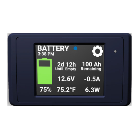
1
Battery Image Indicator
Battery Percentage
2
Remaining
3
Battery Temperature
4
Battery Voltage
5
Input/Output Power (+/-)
Find tech tips, manuals and support at gopowersolar.com/BMG
Scan for full manual
10
9
8
7
6
5
4
NO.
DESCRIPTION
No.
Descrip�on
6
Input/Output Current (+/-)
7
Ah Remaining
8
Settings
9
Time Remaining
10
Connectivity Icon
Advertisement
Table of Contents

Related Manuals for Go Power DOMETIC GP-BMG


Summary of Contents for Go Power DOMETIC GP-BMG
- Page 1 SPECIFICATIONS Scan for full manual DISPLAY Size 3.2” GP-BMG Resolution 320x240 Touchscreen Resistive BATTERY MANAGER Viewing Angle Short axis 70° | Long axis 55° Quick Start Guide ELECTRICAL Supply Voltage 7.5 to 76 VDC Max Supply Current @ 12 VDC Input 150 mA Max Supply Current @ 24 VDC Input 80 mA...
- Page 2 INSTALLATION AND WIRING - OVERVIEW Install the shunt as shown in the wiring diagram on the previous page. Note: The negative terminal of the battery must connect directly to the proper The GP-BMG shunt should be mounted as close to the battery as possible and the side of the shunt and there should be no other connections to the negative remote display is intended to be mounted on a wall.
Need help?
Do you have a question about the DOMETIC GP-BMG and is the answer not in the manual?
Questions and answers