Table of Contents
Advertisement
Available languages
Available languages
Quick Links
ALCA-NHB
R32
Manual de instalación y usuario
Installation and owner's manual
Manuel d'installation et l'utilisauter
Benutzer- oder Installationshandbuch
Manual de instalação e do utilizador
Requisitos de información
Information requirements
Exigences en matière d'information
Informationsanforderungen
Requisitos de informação
CL81011 ~ CL81018
www.auxspain.es
Advertisement
Chapters
Table of Contents

Subscribe to Our Youtube Channel
Related Manuals for AUX ALCA-NHB


Summary of Contents for AUX ALCA-NHB
- Page 1 ALCA-NHB Manual de instalación y usuario Installation and owner's manual Manuel d'installation et l'utilisauter Benutzer- oder Installationshandbuch Manual de instalação e do utilizador Requisitos de información Information requirements Exigences en matière d'information Informationsanforderungen Requisitos de informação CL81011 ~ CL81018 www.auxspain.es...
- Page 2 Manual de instalación y usuario Installation and owner's manual Manuel d'installation et l'utilisauter Benutzer- oder Installationshandbuch Manual de instalação e do utilizador ..............................................................................................................................EU 2016/2281 Requisitos de información (para equipos > 12kW) Information requirements (for units > 12kW) Exigences en matière d'information (pour l'équipement >...
-
Page 3: Table Of Contents
Manual de Instalación y Usuario ÍNDICE PRECAUCIONES DE SEGURIDAD.………………………………………………………………………………….….4 MANUAL DE INSTALACIÓN.…………………………………………………………………………………………..8 ACCESORIOS…………………………………………………………………………………………………….…8 INSTALACIÓN DE LA UNIDAD INTERIOR………………………………………………………………9 INSTALACIÓN DE LA UNIDAD EXTERIOR……………………………………………………………10 INSTALACIÓN DE LA TUBERÍA DE REFRIGERANTE…………………………………………..…12 INSTALACIÓN DE LA TUBERIA DE DRENAJE…………………………………………….…………14 CABLEADO ELÉCTRICO………………………………………………………………………………………15 PRUEBA DE FUNCIONAMIENTO.……………………………….…………..………………………… MANUAL DE USUARIO.……………………………….…………..……………………………………………………19 DENOMINACIÓN DE LAS PARTES…….…………..……………………………………………..……19 FUNCIONES Y RENDIMIENTO DEL AIRE ACONDICIONADO…….…………..……..…….. -
Page 4: Precauciones De Seguridad
Precauciones de seguridad Lea las precauciones de seguridad antes de operar e instalar Una instalación incorrecta debido a hacer caso omiso de las instrucciones puede causar serios problemas. La gravedad de los posibles daños o lesiones se clasifica como ADVERTENCIA o PRECAUCIÓN. - Page 5 ADVERTENCIAS DE LIMPIEZA Y MANTENIMIENTO • Apague el dispositivo y desconecte la corriente antes de limpiarlo. Si no lo hace, puede provocar una descarga eléctrica. • No limpie el aire acondicionado con cantidades excesivas de agua.. • No limpie el aire acondicionado con agentes de limpieza inflamables.. Los agentes de limpieza inflamables pueden causar incendios o deformaciones.
- Page 6 ADVERTENCIAS SOBRE LA INSTALACIÓN DEL PRODUCTO 1. La instalación debe ser realizada por un distribuidor o especialista autorizado. Una instalación defectuosa puede causar fugas de agua, descargas eléctricas o incendios. 2. La instalación debe realizarse de acuerdo con las instrucciones de instalación. Una instalación mal hecha puede causar fugas de agua, descargas eléctricas o incendios.
- Page 7 Precauciones para el uso del refrigerante R32 7. Tenga mucho cuidado de que no entren cuerpos extraños (aceite, agua, etc.) en la tubería. Además, al almacenar la tubería, selle con seguridad la abertura y pegue con cinta adhesiva. Para las unidades interiores, utilice el conjunto de unión no abocardado R32 solo cuando conecte la unidad interior y conecte las tuberías (cuando conecte en interiores).
-
Page 8: Manual De Instalación
MANUAL DE INSTALACIÓN ACCESORIOS Asegurarse de que estos accesorios vengan provistos con el equipo. NOMBRE ELEMENTOS CANTIDAD Racores de la tubería de drenaje Pipeta de drenaje de la unidad exterior AUTO RUN ROOM COOL HEAT AUTO SILE TURBO... -
Page 9: Instalación De La Unidad Interior
1. INSTALACIÓN DE LA UNIDAD INTERIOR Modelo 24: 1.1 Elección del lugar de instalación Cuando las condiciones en el techo son superiores a 30ºC y una humedad relativa de 80%, o cuando se instale una aportación de aire fresco en el techo, se requiere un aislamiento adicional (espesor de 10 mm como mínimo, de espuma de polietileno). -
Page 10: Instalación De La Unidad Exterior
INSTALACIÓN DE LA UNIDAD EXTERIOR Dimensiones del equipo Precauciones al seleccionar la ubicación 1) Seleccione un lugar bien firme que soporte el peso y la vibración de la unidad, donde no se amplifique el ruido de funcionamiento. 2) Tenga en cuenta que la descarga de aire de la unidad o el ruido no moleste a los vecinos. - Page 11 2.4 Instalación de la unidad exterior 2.3 Guía de instalación ■ Instalación individual Instalación de la unidad exterior Modelos 18 a 42: Al instalar la unidad exterior consulte "Precauciones al seleccionar la ubicación". Compruebe la solidez y la nivelación de la instalación para evitar que la unidad provoque vibraciones o ruidos después de instalada.
-
Page 12: Instalación De La Tubería De Refrigerante
Caso 2 Caso 1 INSTALACIÓN DE LA TUBERÍA DE A: Vertical REFRIGERANTE B: Total Todas las tuberías las debe suministrar un especialista en refrigeración y deben cumplir la normativa nacional correspondiente. Precauciones Aísle térmicamente ambos lados completos de las tuberías de gas y líquido. - Page 13 2) Abra completamente la válvula de baja presión del puente de 5) Compruebe que el ensanchamiento está bien manómetros (baja) y cierre su válvula de alta presión (alta). realizado. El extremo de la tubería (Por tanto la válvula de alta presión no necesita manipulación). debe estar ensanchado de forma pareja en un ...
-
Page 14: Instalación De La Tuberia De Drenaje
3.5 Trabajo de las tuberías de refrigerante INSTALAR LA TUBERÍA DE DRENAJE 1) Precauciones en la manipulación de los tubos 4.1 Instale las tuberías de drenaje. Proteja el extremo abierto de la tubería del polvo y Mantener la tubería lo más corta posible y tiéndala en la humedad. -
Page 15: Cableado Eléctrico
Sección transversal nominal mínima de los cables: 5. CABLEADO ELÉCTRICO Consumo de Instrucciones generales Sección nominal corriente del Todos los cables y componentes los debe instalar un electricista equipo (A) autorizado y deben cumplirse las directivas europeas y <6 0,75 nacionales correspondientes. - Page 16 Modelos 36 / 42: Modelos 48 / 60: Unidad Exterior Unidad Exterior 2 x 0,75mm2 (apantallado) 2 x 0,75mm2 (apantallado) Unidad Interior Unidad Interior Nota: - Se debe realizar el conexionado eléctrico según lo indicado en los diagramas, de lo contrario se podría dañar el equipo. - Conectar el tierra correctamente, de lo contrario podrían ocurrir errores de funcionamiento o dañar algún componente del equipo, pudiendo incluso incendiarse.
- Page 17 Ajustar la función de ON/OFF remoto: - Valores por defecto: Parám. - Ajuste Descripción Sin función de ON/OFF remota (por defecto) 09 - 00 09 - 01 Con función de ON/OFF remota - Pasos a seguir para realizar el ajuste: 1.
-
Page 18: Prueba De Funcionamiento
PRUEBA DE FUNCIONAMIENTO Una protección evita que el aire acondicionado se active Verifique que las tapas de la caja de control están cerradas en ambas durante 3 minutos cuando se reinicia si estaba desconectado unidades. de la corriente. Consulte para más detalles: "Cuidado especial durante la construcción para los siguientes elementos y comprobar tras concluir la instalación". -
Page 19: Manual De Usuario
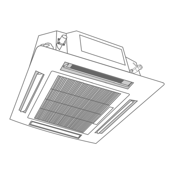
MANUAL DE USUARIO DENOMINACIÓN DE LAS PARTES UNIDAD INTERIOR RUN ROOM AUTO COOL HEAT AUTO SILE TURBO SPEED HEALTH iFavor SWING LRSWING DISPLAY SLEEP POWERCON iFEEL iCLEAN Anti-F LOCK ELE.H ON/OFF SPEED COOL HEAT SWING SWING UNIDAD EXTERIOR ... -
Page 20: Funciones Y Rendimiento Del Aire Acondicionado
1. FUNCIONES Y RENDIMIENTO DEL Si el filtro de aire está obstruido se reducirá el AIRE ACONDICIONADO rendimiento tanto de la calefacción como de la refrigeración, limpie el filtro una vez cada dos semanas. Use el sistema en las temperaturas siguientes para MANTENIMIENTO lograr funcionamiento... -
Page 21: Sintomas Que Nos Son Problemas Del Aire Acondicionado
Limpieza del filtro de aire Síntoma 3: Sale neblina blanca por la unidad Síntoma 3.1: Unidad interior El filtro de aire evita que entre polvo u otras partículas en el La distribución de la temperatura en la habitación será irregular equipo. -
Page 22: Localización De Averías
5. LOCALIZACIÓN DE AVERÍAS Problemas del aire acondicionado y sus PRECAUCIÓN causas Desconecte el equipo de la corriente cuando aparezcan Si ocurre una de las siguientes averías, detenga el los fallos siguientes, compruebe si el voltaje está fuera funcionamiento del equipo, desconéctelo de la electricidad y de rango, si la instalación del aire acondicionado es póngase en contacto con su instalador autorizado. - Page 23 Tabla 5-2 Problemas comúnes Síntomas Causas Solución Fallo de corriente. Espere a que regrese el El interruptor está apagado. suministro eléctrico. El fusible del interruptor puede estar La unidad no enciende Encienda el interruptor. fundido. • Sustituya las baterías o compruebe el •...
-
Page 24: Guía De Eliminación De Residuos
6. GUÍA DE ELIMINACIÓN DE RESIDUOS Este equipo contiene refrigerante y otros materiales potencialmente peligrosos. Para desechar este equipo la legislación exige que se usen los canales de recolección y tratamiento de equipos usados. No elimine este producto como desecho común junto con otros residuos domésticos no clasificados. Al eliminar la unidad tiene las siguientes opciones: •... -
Page 25: Control Remoto
CONTROL REMOTO 1. ESPECIFICACIONES YKR-L/101E YKR-L/101E Modelo Voltaje nominal 3.0 V (Batería AAA x 2) Rango de alcance de la señal Temp. Ambiente -5ºC a 60ºC El diseño de botones se basa en el modelo estándar y puede ser ligeramente diferente del que usted ha adquirido, la forma real prevalecerá. - Page 26 2. FUNCIÓN DE LOS BOTONES Transmisor de señal Parte exterior:...
- Page 27 Parte interior: Transmisor de señal...
- Page 29 Esta función realiza una auto limpieza en la unidad interior. Cuando se activa la función "iClean", inicialmente la unidad funciona en modo refrigeración con el ventilador a baja velocidad, durante este período el agua de condensación arrastra el polvo de la batería. Seguidamente la unidad cambia a modo calefacción con el ventilador a baja velocidad, para secar la bateria y el interior de la unidad.
- Page 30 Presione este botón para ingresar al modo SLEEP, al cual la unidad saldrá después de 10 horas de operación continua y volverá al estado anterior. Nota: El modo nocturno no está disponible en los modos FAN o DRY. Este botón no tiene función en este equipo.
- Page 32 3. FUNCIONAMIENTO...
- Page 33 4. CAMBIO DE LAS BATERÍAS 5. ATENCIÓN...
-
Page 34: Información De Servicio
INFORMACIÓN DE SERVICIO Por favor, tenga en cuenta toda la información de servicio antes de realizar cualquier tarea de instalación, mantenimiento o manipulación de este equipo de aire acondicionado con gas R-32. - Page 35 1. Comprobaciones de la zona de trabajo Antes de comenzar el trabajo en los sistemas que contengan refrigerantes inflamables, son necesarios los controles de seguridad para asegurar que el riesgo de incendio está minimizado. Para reparar el sistema refrigerante se deben cumplir las siguientes precauciones antes de realizar los trabajos en el sistema.
- Page 36 La cantidad de carga es según el tamaño del compartimento dentro del cual se instalan las piezas. El ventilador y las salidas están funcionando bien y no están obstruidas. Si se usa un circuito indirecto de refrigerante, el circuito secundario se debe comprobar en búsqueda de refrigerante.
- Page 37 11. Reparación de componentes seguros No aplique ningún inductor permanente o cargas de capacitancia al circuito sin asegurar que esto no excederá el voltaje ni la corriente permisible para el equipo en uso. Estos componentes seguros son los únicos con los que se puede trabajar en una ambiente de gases inflamables. El comprobador debe tener el rango correcto.
- Page 38 Cuando la carga OFN se usa, se debe ventilar el sistema para que baje a la presión atmosférica y de esta manera permitir que funcione. Esta operación es vital cuando se va a soldar. Asegúrese de que la salida de la bomba de vacío no está cerrada a fuentes de ignición y de que hay ventilación.
- Page 39 18. Etiquetado El equipo se debe etiquetar mencionando que está reparado y sin refrigerante. La etiqueta debe tener la fecha y la firma. Asegúrese de que hay etiquetas en el equipo con la actualización del estado del refrigerante inflamable. 19. Recuperación Se recomienda usar las buenas prácticas recomendadas cuando extraiga el refrigerante ya sea por mantenimiento o instalación.
- Page 40 Installation and Owner's Manual CONTENT SAFETY PRECAUTIONS.………………………………………………………………………………….……………..41 INSTALLATION MANUAL. …………………………………………………………………………………………..45 ACCESSORIES…………………………………………………………………………………..……………….45 INDOOR UNIT INSTALLATION……………………………………………………………………………46 OUTDOOR UNIT INSTALLATION ………………………………………………………………….……47 INSTALL THE REFRIGERANT PIPE………………………………………………………..………….…49 CONNECT THE DRAIN PIPE…………………………………………………………….…….………….. ELECTRIC WIRING WORK……………………………………………………………………………….…52 TEST RUN.……………………………….…………..………………………………………………..…………55 OWNER’S MANUAL.……………………………….…………..……………………………………………………..…56 PART NAMES…….…………..………………………………………………………………………..……56 AIR CONDITIONER OPERATIONS AND PERFORMANCE…….…………..……..………..HITS FOR ECONOMICAL OPERATION…….…………..………………………………………...…..57 MAINTENANCE…….…………..……………………………………………………..………………….…..57 FOLLOWING SYMPTOMS ARE NOT AIR CONDITIONER TROUBLES…………..……..…58...
-
Page 41: Safety Precautions
Safety Precautions Read Safety Precautions Before Operation and Installation Incorrect installation due to ignoring instructions can cause serious damage or injury. The seriousness of potential damage or injuries is classified as either a WARNING or CAUTION. CAUTION WARNING This symbol indicates the possibility of This symbol indicates the possibility property damage or serious consequences. - Page 42 CAUTION Turn off the air conditioner and disconnect the power if you are not going to use it for a long time. • Turn off and unplug the unit during storms. • Make sure that water condensation can drain unhindered from the unit. •...
- Page 43 WARNINGS FOR PRODUCT INSTALLATION 1. Installation must be performed by an authorized dealer or specialist. Defective installation can cause water leakage, electrical shock, or fire. 2. Installation must be performed according to the installation instructions. Improper installation can cause water leakage, electrical shock, or fire. 3.
- Page 44 WARNING for Using R32 Refrigerant 3. Do not use means to accelerate the defrosting process or to clean, other than those recommended by the manufacturer. 4. The appliance shall be stored in a room without continuously operating ignition sources (for example: open flames,an operating gas appliance or an operating electric heater) 5.
-
Page 45: Installation Manual
INSTALLATION MANUAL ACCESSORIES Please check whether the following fittings are of full scope. If there are some spare fittings , please restore them carefully. NAME SHAPE QUANTITY Drainpipe fittings Drain joint RUN ROOM AUTO COOL ... -
Page 46: Indoor Unit Installation
Model 24: Fig.1-2 Unit: mm Models 30 to 60: Models 12 and 18: Fig.1-3 Unit: mm Fig.1-1 Unit: mm... -
Page 47: Outdoor Unit Installation
OUTDOOR UNIT INSTALLATION Figure of body size Precautions for selecting the location 1) Choose a place solid enough to bear the weight and vibration of the unit, where the operation noise will not be amplified. 2) Choose a location where the hot air discharged from the unit or the operation noise will not cause a nuisance to the neighbours of the user. - Page 48 2.4 Outdoor unit installation 2.3 Installation guidelines Individual installation 1) Installing outdoor unit Models 18 to 42: When installing the outdoor unit, refer to "Precautions for selecting the location" . Check the strength and level of the installation ground so that the unit will not cause any operating vibration or noise after installed.
-
Page 49: Install The Refrigerant Pipe
Case 2 INSTALL THE REFRIGERANT PIPE Case 1 A: Vertical B: Total All field piping must be provided by a licensed refrigeration technician and must comply with the relevant local and national codes. Precautions Execute heat insulation work completely on both sides of the gas piping and liquid piping. - Page 50 1) Connect projection side of charging hose (which comes from 5) Check that the flaring is properly made. gauge manifold) to gas stop valve's service port. The pipe end must 2) Full open gauge manifold's low-pressure valve (Lo) and be evenly flared in a perfect circle.
-
Page 51: Connect The Drain Pipe
3.5 Refrigerant pipig work CONNECT THE DRAIN PIPE 1) Caution on the pipe handling 4.1 Install the drain pipes. Protect the open end of the pipe against dust and moisture. Keep piping as short as possible and slope it downwards at a All pipe bends should be as gentle as possible. -
Page 52: Electric Wiring Work
ELECTRIC WIRING WORK Minimum nominal cross-sectional area of conductors: General instructions Rated current Nominal cross-sectional of appliance area All field wiring and components must be installed by a licensed (mm2) electrician and must comply with relevant European and national <6 0.75 regulations. - Page 53 Models 36 / 42: Models 48 / 60: Outdoor unit Outdoor unit Indoor unit Indoor unit Note: - The connection wire of indoor units should be connected to the corresponding terminals board: otherwise it will cause the unit failure or even damage the units. - Connect the grounded wire correctly, otherwise will cause the malfunction of some electrical component and shock or fire indeed.
- Page 54 Setting the remote ON/OFF function: - Functions setting: Description Setting Without remote ON/OFF function (by default) 0900 With remote ON/OFF function 0901 - Steps to follow to make the adjustment: 1. Feel free to touch a button and light up the screen, as shown in the right picture: 2.
-
Page 55: Test Run
4. Press the “FUNCTION” button for 5S again to enter set interface, the last 2 numbers of “09 ” will be twinkle, then Press “△ ▽” button changing the last 2 numbers of “09 XX" to "01". As shown in the following picture: 5. -
Page 56: Owner's Manual
OWNER'S MANUAL PARTS NAMES INDOOR UNIT RUN ROOM AUTO COOL HEAT AUTO SILE TURBO SPEED HEALTH iFavor SWING LRSWING DISPLAY SLEEP POWERCON iFEEL iCLEAN Anti-F LOCK ELE.H ON/OFF SPEED COOL HEAT SWING SWING OUTDOOR UNIT Air-in grill Air flow louver(at air outlet) Display panel Drain pump(drain water from indoor unit) Remote controller... -
Page 57: Air Conditioner Operations And Performance
A clogged air filter will reduce cooling or heating efficiency, 1. AIR CONDITIONER OPERATIONS AND please clean it once two weeks. PERFORMANCE 3. MAINTENANCE Use the system in the following temperature for safe and effective operation.The Max operation temperature for CAUTION the air conditioner. -
Page 58: Following Symptoms Are Not Air Conditioner Troubles
Cleaning the air filter Symptom 2: Change into the fan mode during cooling mode The air filter can prevent the dust or other particulate from going inside. In case of blockage of the filter , the working efficiency of In order to prevent the indoor evaporator frosting, the system the air conditioner may greatly decrease . -
Page 59: Troubleshooting
5. TROUBLESHOOTING 5.1. T roubles and causes of air conditioner CAUTION If one of the following malfunctions occur, stop operation, shut Please cut off the power supply when appearing the off the power, and contact with your dealer. above malfunction, check if the voltage provided is out of If the system does not properly operate except the above range, check if the installation of air-conditioner is mentioned cases or the above mentioned malfunctions is... - Page 60 Table 5-2 Symptoms Causes Solution Power failure. Wait for the comeback of power. Power switch is off. Switch on the power. Fuse of power switch may have burned. ReplLocation: Unit does not start Batteries of remote controller exhausted Replace the batterises or check the or other problem of controller.
-
Page 61: Disposal Guidelines
6. DISPOSAL GUIDELINES This appliance contains refrigerant and other potentially hazardous materials. When disposing of this appliance, the law requires special collection and treatment. Do not dispose of this product as household waste or unsorted municipal waste. When disposing of this appliance, you have the following options: Dispose of the appliance at designated municipal electronic waste collection facility. -
Page 62: Remote Controller
REMOTE CONTROLLER SPECIFICATIONS YKR-L/101E Model YKR-L/101E Rated Voltage 3.0 V (Dry batteries AAA x 2) Signal Receiving Range Environment -5ºC to 60ºC... - Page 63 2. OPERATION OF BUTTONS Outdoor view:...
- Page 64 Indoor view:...
- Page 66 This function performs a self cleaning the indoor unit. When the 'iClean' function is activated, the unit operates initially mode cooling fan at low speed during this period condensing water entrains the powder battery. then the unit switches to heating mode the fan at low speed, to dry the battery inside the unit.
- Page 67 This button has no function.
- Page 69 3. OPERATION...
- Page 70 4. CHANGING THE BATTERIES 5. ATENTION 1.Aim the remote con troller toward s the receiver on the air- conditio ner. 2.The remote controller s hould be within 8 meters away from the receiver. 3.No obstacle s be tween the re mo te controller and receiver. 4.Do not drop or throw the remote con trolle r.
-
Page 71: Information Servicing
INFORMATION SERVICING Please note all service information before performing any installation, maintenance or handling of this R-32 gas air conditioner. - Page 72 1. Checks to the area Prior to beginning work on systems containing flammable refrigerants, safety checks are necessary to ensure that the risk of ignition is minimised. For repair to the refrigerating system, the following precautions shall be complied with prior to conducting work on the system. 2.
- Page 73 the charge size is in accordance with the room size within which the refrigerant containing parts are installed; the ventilation machinery and outlets are operating adequately and are not obstructed; if an indirect refrigerating circuit is being used, the secondary circuits shall be checked for the presence of refrigerant;...
- Page 74 11. Repair to intrinsically safe components Do not apply any permanent inductive or capacitance loads to the circuit without ensuring that this will not exceed the permissible voltage and current permitted for the equipment in use. Intrinscially safe components are the only types that can be worked on while live in the presence of a flammable atmosphere.
- Page 75 When the final OFN charge is used, the system shall be vented down to atmospheric pressure to enable work to take place. This operation is absolutely vital if brazing operations on the pipe-work are to take place. Ensure that the outlet for the vacuum pump is not closed to any ignition sources and there is ventilation available.
- Page 76 18. Labelling Equipment shall be labelled stating that it has been de-commissioned and emptied of refrigerant. The label shall be dated and signed. Ensure that there are labels on the equipment stating the equipment contains flammable refrigerant. 19. Recovery When removing refrigerant from a system, either for service or decommissioning, it is recommended good practice that all refrigerants are removed safely.
- Page 77 REQUISITOS DE INFORMACIÓN Refrigeración - Requisitos de información para acondicionadores de aire aire-aire Requisitos de información para acondicionadores de aire aire-aire Unidad(es) interior(es) ALCA-42-NHB-I Modelo(s): Unidad exterior ALE-42-NHB-E Intercambiador de calor de exterior del acondicionador de aire: Aire Intercambiador de calor de interior del acondicionador de aire: Aire Tipo: compresión de vapor por compresor Si procede, accionamiento del compresor: motor eléctrico Elemento...
- Page 78 Calefacción - Requisitos de información para bombas de calor Requisitos de información para bombas de calor Unidad(es) interior(es) ALCA-42-NHB-I Modelo(s): Unidad exterior ALE-42-NHB-E Intercambiador de calor de exterior del acondicionador de aire: Aire Intercambiador de calor de interior del acondicionador de aire: Aire Indicación de si el calefactor está...
- Page 79 EU 2016/2281 Information requirements (for units > 12kW) CONTENT Information requirements for air-to-air air conditioners ........Information requirements for heat pumps ............
- Page 80 INFORMATION REQUIREMENTS Cooling - Information requirements for air-to-air air conditioners Information requirements for air-to-air air conditioners ALCA-42-NHB-I Indoor unit(s) Model(s): ALE-42-NHB-E Outdoor unit Outdoor side heat exchanger of air conditioner: Air Indoor side heat exchanger of air conditioner: Air Type: compressor driven vapour compression If applicable: driver of compressor: electric motor Item Symbol...
- Page 81 Heating - Information requirements for heat pumps Information requirements for heat pumps ALCA-42-NHB-I Indoor unit(s) Model(s): ALE-42-NHB-E Outdoor unit Outdoor side heat exchanger of heat pump: Air Indoor side heat exchanger of heat pump: Air Indication if the heater is equipped with a supplementary heater: no If applicable: driver of compressor: electric motor Parameters shall be declared for the average heating season, parameters for the warmer and colder heating seasons are optional.
- Page 82 C/ ROSSELLÓ 430-432 08013 BARCELONA SPAIN (+34) 93 446 27 80...
Need help?
Do you have a question about the ALCA-NHB and is the answer not in the manual?
Questions and answers