Table of Contents
Advertisement
All manuals and user guides at all-guides.com
Split type Wall Mounted Air Conditioner
E series
Service Manual
Contents
1.Important Notice.............................................1
2.Technical Specification................................2-9
3.Operation Details.....................................10-13
4.Wiring Diagram.......................................14-15
5.Troubleshooting Guide.............................16-23
6.Explosion View And Parts List..................24-31
7.Refrigeration Cycle Diagram........................32
8. Control Functions Exposition..................33-42
Advertisement
Table of Contents

Related Manuals for AUX ASW-09A4/EA


Summary of Contents for AUX ASW-09A4/EA
-
Page 1: Table Of Contents
All manuals and user guides at all-guides.com Split type Wall Mounted Air Conditioner E series Service Manual Contents 1.Important Notice..........1 2.Technical Specification........2-9 3.Operation Details........10-13 4.Wiring Diagram........14-15 5.Troubleshooting Guide......16-23 6.Explosion View And Parts List....24-31 7.Refrigeration Cycle Diagram......32 8. Control Functions Exposition....33-42... -
Page 2: Important Notice
All manuals and user guides at all-guides.com IMPORTANT NOTICE This service manual is intended for use by individuals possessing adequate backgrounds of electrical, electronic and mechanical experience. Any attempt to repair the appliance may result in personal injury and property damage. -
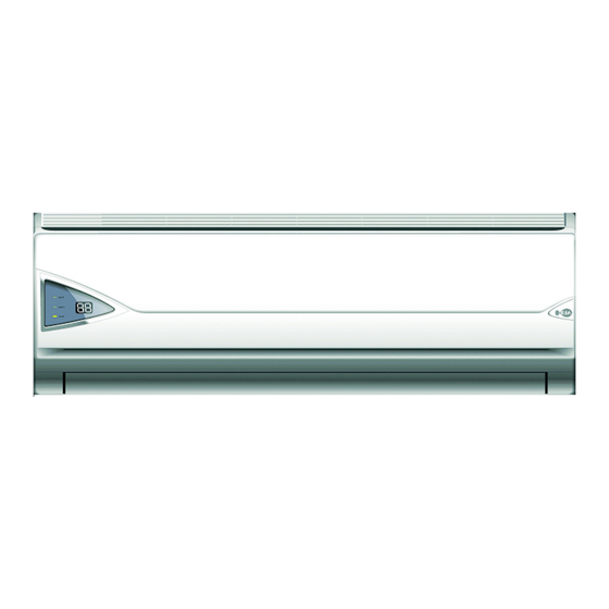
Page 3: Technical Specification
All manuals and user guides at all-guides.com 2.Technical Specification 2-1 Appearance... - Page 4 All manuals and user guides at all-guides.com 2.Technical Specification 2-1 Appearance(continue) INDOOR UNIT OUTDOOR UNIT...
- Page 5 All manuals and user guides at all-guides.com 2.Technical Specification 2-2 Nomenclature 1 AUX 2 Split-type 3 Wall mounted 4 Heat pump(only for heat pump) 5 Rated cooling capacity 6 The lever code of same cooling capacity 7 Power supply 1 for 220V~/50Hz...
- Page 6 All manuals and user guides at all-guides.com 2.Technical Specification 2-3 Product Technical Specification Diagram Model Item Indoor Outdoor Indoor Outdoor Indoor Outdoor Indoor Outdoor Type Wall mounted Wall mounted Wall mounted Wall mounted Cooling Dehumidifying Heating Cooling Air Flow Volume Heating Cooling Noise...
- Page 7 All manuals and user guides at all-guides.com 2.Technical Specification 2-3 Product Technical Specification Diagram Model Item Indoor Outdoor Indoor Outdoor Type Wall mounted Wall mounted Cooling Dehumidifying Heating Cooling Air Flow Volume Heating Cooling Noise Heating Power supply Cooling Rated input Heating Cooling...
- Page 8 All manuals and user guides at all-guides.com 2.Technical Specification 2-3 Product Technical Specification Diagram(continue) Model Item Indoor Outdoor Indoor Outdoor Indoor Outdoor Indoor Outdoor Type Wall mounted Wall mounted Wall mounted Wall mounted Cooling Dehumidifying Heating Cooling Air Flow Volume Heating Cooling Noise...
- Page 9 All manuals and user guides at all-guides.com 2.Technical Specification 2-3 Product Technical Specification Diagram Model Item Indoor Outdoor Indoor Outdoor Type Wall mounted Wall mounted Cooling Dehumidifying Heating Cooling Air Flow Volume Heating Cooling Noise Heating Power supply Cooling Rated input Heating Cooling...
- Page 10 All manuals and user guides at all-guides.com 2.Technical Specification 2-3 Product Technical Specification Diagram(continue) Model Item Indoor Outdoor Indoor Outdoor Indoor Outdoor Indoor Outdoor Type Wall mounted Wall mounted Wall mounted Wall mounted Cooling Dehumidifying Heating Cooling Air Flow Volume Heating Cooling Noise...
-
Page 11: Operation Details
All manuals and user guides at all-guides.com Operation Details Remote Controller button The closing state of remote controller: This button can set room temperature. Press it once ,the temperature increases 1 .Press it continu- Mode display ously, the temperature increases at the speed of 4 /s. This function is invalid when the appliance at the Fan and Auto Cool Dry Heat Wet Emission display... - Page 12 All manuals and user guides at all-guides.com Operation Details Remote Controller(continue) button This button not only can adjust clock time and the timer time but also can set room humidity. Adjusting clock time and timer time The opening state of remote controller: Press it once ,the time increases one minute.
- Page 13 All manuals and user guides at all-guides.com Operation Details 3-2 Operation Method TIMER/CLOCK button Setting the ON/OFF timer time When remote controller is at the on/off state, Press this button , the LCD flickers the symbol. Press the + or - button to set the timer time.
- Page 14 All manuals and user guides at all-guides.com Operation Details 3-2 Operation Method(continue) 3.Press the + or - button, you can set the temperature range from 16 to 32 . 4.Press the FAN button, you can select fan speed from Low , Med , High , Auto .
-
Page 15: Wiring Diagram
All manuals and user guides at all-guides.com 4. Wiring Diagram 4-1 ASW- H 24B4/E*Indoor Unit... - Page 16 All manuals and user guides at all-guides.com 4. Wiring Diagram 4-2 ASW- H 18B4/E* Indoor Unit Black Fan Motor Fan Motor Capacitor Brown Orientation White Valve Overcurrent Protector Black Black Compressor Blue Blue Yellow Green Yellow Compressor Capacitor Yellow Brown Green Blue Black To Indoor Unit...
-
Page 17: Troubleshooting Guide
All manuals and user guides at all-guides.com 5.Troubleshooting Guide 5-1The Foremost Inspecting Items 1.The input voltage must be within +10% tolerance of the rated Voltage. If it is not the case, the air-conditioner will probably not work normally. 2.Check the connecting cord between indoor unit and outdoor unit to see if it is properly connected. - Page 18 All manuals and user guides at all-guides.com 5.Troubleshooting Guide 5-2 No Power Display 1.Items 1 Check if the input voltage is correct? 2 Check if the AC power supply connecting is correct? 3 Check if the output voltage of the manostat L7805(IC2)is correct? 2.Trouble shooting procedure Pull out the power plug and replug it after some 5 seconds...
- Page 19 All manuals and user guides at all-guides.com 5.Troubleshooting Guide 5-3 The Indoor Fan Motor Does Not Work 1.Items 1 Check if the indoor fan motor is connected correctly to the connector(CN8)? 2 Check if the AC input voltage is correct? 3 Check if the IC of indoor fan motor is connected correctly to the connector(CN2)? 4 Check if the capacity of indoor fan motor is connected correctly to the connector(CN8)? 2.Trouble shooting procedure...
- Page 20 All manuals and user guides at all-guides.com 5.Troubleshooting Guide 5-4 The Outdoor Unit Does Not Work 1.Items Check if the input voltage is correct? Check if the wire connection of the outdoor connecting terminal is correct? 2.Trouble shooting procedure Pull out the power plug and replug it after some 5 seconds Check refer to the 5-2 part Is the indoor controller normal?
- Page 21 All manuals and user guides at all-guides.com 5.Troubleshooting Guide 5-5 The Step Motor Does Not Work 1.Items Check if the input voltage is correct? Check if the step motor controlling the up-down movement firmly connected to Cn2? 2.Trouble shooting procedure Pull out the power plug and replug it after some 5 seconds Start the air-conditioner with remote control Confirm the procedure of...
- Page 22 All manuals and user guides at all-guides.com 5.Troubleshooting Guide 5-6 Heating Mode Can Work, But No Hot Air Blow Check if the set temperature is lower than the indoor temperature? Check if the indoor PCB is connected to the terminal correctly? restarted in some 5 minutes Normal after the above problems solved...
- Page 23 All manuals and user guides at all-guides.com 5.Troubleshooting Guide 5-7 Remote Control Can Not Work Trouble shooting procedure Take out the batteries and reinsert them after 5 seconds Is the LED lighten? Check refer to the 5-2 part Is there music when the ON/OFF button was Normal pressed.
- Page 24 All manuals and user guides at all-guides.com 5.Troubleshooting Guide 5-8 The Failure Analysis Of The Main Parts Analysis Part Measure resistance Environment Heat exchanger temperature Normal Resistance of transformer(K Abnormal Turn-off Short-cut Detecting the resistance between each connecting terminal Environment temperature Between Blue yellow Main...
-
Page 25: Explosion View And Parts List
All manuals and user guides at all-guides.com 6. Explosion View And Parts List Explosion View Of Indoor Unit E-type E xplosion View Fig.1... - Page 26 All manuals and user guides at all-guides.com 6. Explosion View And Parts List 6-2 Parts List Indoor Unit MODE ASW-(H)09A4/E* ASW-(H)12A4/E*R ASW-(H)12B4/E*R1 Quantity Character Remarks Name Fig.1-01 Front panel Fig.1-02 Air filter Fig.1-03 Bolt cover Fig.1-04 Vane shelf assembly Fig.1-04a Vane Fig.1-04b Louver assembly...
- Page 27 All manuals and user guides at all-guides.com 6. Explosion View And Parts List Explosion View Of Out door Unit Fig.2...
- Page 28 All manuals and user guides at all-guides.com 6. Explosion View And Parts List 6. Explosion View And Parts List 6-4 Parts List Of Out door Unit MODE AS-(H)09A4/E* Quantity Remarks Code Name Character Cold-work steel Top cover Axial-flow fan leaves Outdoor motor Motor supporter Galvanized steel...
- Page 29 All manuals and user guides at all-guides.com 6. Explosion View And Parts List 6. Explosion View And Parts List 6-4 Parts List Of Out door Unit MODE AS-(H)12A4/E* Quantity Remarks Code Name Character Cold-work steel Top cover Axial-flow fan leaves Outdoor motor Motor supporter Galvanized steel...
- Page 30 All manuals and user guides at all-guides.com 6. Explosion View And Parts List 6. Explosion View And Parts List 6-4 Parts List Of Out door Unit MODE AS-(H)12B4/E* Quantity Remarks Code Name Character Cold-work steel Top cover Axial-flow fan leaves Outdoor motor Motor supporter Galvanized steel...
- Page 31 All manuals and user guides at all-guides.com 6. Explosion View And Parts List 6-11 Explosion View Of Controller(In door Unit) Connection wire of display board 450 Sensor of indoor pipe 350 Sensor of indoor room 350 Fig.4...
- Page 32 All manuals and user guides at all-guides.com 6. Explosion View And Parts List 6-12 Parts List Of Controller(Indoor Unit) PP white Indicator shelf PP white Receiver of remote control Display board Bolt Main control board Transformer TDB-6-B4 Black Bolt Spring gasket Bolt Yellow/green Grounding wire...
-
Page 33: Refrigeration Cycle Diagram
All manuals and user guides at all-guides.com 7.Refrigeration Cycle Diagram Indoor Unit Outdoor Unit Capillary Single-way vavle Two-way vavle Liquid side Auxillary capillary Evaporator Condensor Air side 4-way vavle Two-way vavle Cool Heat Compressor The gas leak checking point Fig.5... -
Page 34: Control Functions Exposition
All manuals and user guides at all-guides.com 8.Function Exposition 8-1Terminologies and their denotation TA: Indoor environment temperature TE: Indoor evaporator temperature TS: Set temperature 8-2 Forced operation button a) When the air-conditioner is on, press this button you will turn it off; when the air-conditioner is off, press this button you will turn it on and it will run at automatic mode afterwards, then the indicator light will glint for 20 seconds until it runs at your selected mode. - Page 35 All manuals and user guides at all-guides.com 8.Function Exposition 8 4 Cooling mode The temperature is controlled by pressing the + or -button on the remote control between 16 C and 32 C.You can select fan speed from Low, Med, High, Auto. The 4-way valve will keep closed at this mode, and other status are demonstrated as follows: 1.When TA-TS>1 C and it is operated after the compressor protection duration ,the compressor and outdoor fan motor will be running;...
- Page 36 All manuals and user guides at all-guides.com 8.Function Exposition 3.When first powered, the 3-minute protection will be off ,and the outdoor fan motor will run after the compressor keeps running for 2s; 4.When the indoor fan motor is running, the vane can be set move freely as the that of the cooling mode;...
- Page 37 All manuals and user guides at all-guides.com 8.Function Exposition 9.the cold air prevention and remaining-heat expelling function The indoor fan speed is controlled by TE, the retails are as following: The cold air prevention function when the compressor is running: a)When TE is going up: when TE<25 C, the indoor fan motor will be off;...
- Page 38 All manuals and user guides at all-guides.com 8.Function Exposition The remaining-heat expelling function when the air-condition is powered off when TE>35 C, the indoor fan motor will run at slight speed; when TE<35 C, the indoor fan motor will be off, and it will keep expelling the remaining heat for no more than 10 seconds, during which the indoor fan motor will stop running immediately if TE<35 C.
- Page 39 All manuals and user guides at all-guides.com 8.Function Exposition 3.1)the compressor runs totally for at least 3 hours; 2)the compressor keeps running for at least 20 minutes; 3)the difference between TE and TA is less than 16 C; 4.1)the difference between TE and TA is less than 16 C and lasts for 5 minutes; 2).the compressor runs totally for at least 45 minutes;...
- Page 40 All manuals and user guides at all-guides.com 8.Function Exposition Sleeping function at cooling mode Set temperature Go down for 2 C Original set Another 2 C temperature Quit the sleeping function and powered off automatically) 8 11 Timer Function The longest timing interval is 24 hours( 1minute as the unit), and once the timer is set, it will not be changed even modes are shifted and the indicator will be lighten.
- Page 41 All manuals and user guides at all-guides.com 8.Function Exposition If no impulse signal feedback from the indoor motor 10 second after it was filled with voltage, the controller will turn off automatically, 30 second later it will restart and impose voltage to the indoor motor again, if still no impulse signal were detected the controller will hold on, at the same time the digital tube will show the malfunction code as E4, if you turn off the power, the malfunction display will disappear.
- Page 42 All manuals and user guides at all-guides.com 8.Function Exposition 8-15 Fan speed option The resistance of blowing option as below High Midium The instruction of contr ller of E series wall mounted type Remark: Quiet blowing speed, heating mode is 850r/min, while non heating mode is 800r/min; low speed is 650r/min.
- Page 43 All manuals and user guides at all-guides.com 2) Quit the function a) press the corresponding button on the remote control one more time; b) Aim at the receiver of the controller, the remote control will send signal to the controller per 3s, if the controller can t receive signal from remote control, this function will quit automatically, TA will control temperature according to the TA sensor in the controller.
- Page 44 All manuals and user guides at all-guides.com...
Need help?
Do you have a question about the ASW-09A4/EA and is the answer not in the manual?
Questions and answers