Table of Contents
Advertisement
Advertisement
Table of Contents
Troubleshooting

Related Manuals for AUX FREEDOM Series


Summary of Contents for AUX FREEDOM Series
- Page 1 FREEDOM SERIES ASW-NFH3 www.auxspain.es CL80025 ~ CL80028...
- Page 2 This manual is for professional maintenance personnel only...
-
Page 3: Table Of Contents
9-2 Display error code of outdoor unit's indicator lights ............61 9-3 Troubleshooting for Normal Malfunction ................63 10. Removal Procedure ....................70 10-1 Indoor Unit ........................... 70 10-2 Outdoor Unit ......................... 75 Appendix ........................84 AUX Common Sensor R-T Analysis Table ..................84... -
Page 4: Part I : Technical Information
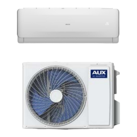
Part I : Technical Information 1. Summary 1-1 Appearance Indoor Unit ➢ Outdoor Unit ➢ 9K-24K Note: The outdoor grille can be replaced. -
Page 5: Model List
1-2 Model List MODEL MODEL ASW-09-NFH3-I/ASW-09-NFH3-E ASW-24-NFH3-I/ASW-24-NFH3-E ASW-12-NFH3-I/ASW-12-NFH3-E ASW-18-NFH3-I/ASW-18-NFH3-E... -
Page 6: Outline Dimension Diagram
2. Outline Dimension Diagram The following data is for reference only and the actual size may vary. 2-1 Indoor Unit(Unit: mm)... - Page 8 2-2 Outdoor Unit(Unit: mm) 0.8PA 1.3PA 2.3PA...
-
Page 9: Specification Sheet
3. Specification sheet Product Model ASW-09-NFH3-I/ASW-09-NFH3-E Cooling 2600(600-3100) Rated Capacity Heating 2610(800-3400) Dehumidifying Kg/h Cooling 850(100-1600) Rated Power Consumption Heating 630(300-1600) Cooling 3.9(0.9-6.9) Rated Running Current Heating 3.0(1.3-6.9) Electric heating power Max. Input Power 1600 Max. Input Current Nameplate EER Cooling Parameter COP Heating Power supply source... - Page 10 Refrigerant Charged Max. Discharge Pressure Max. Suction Pressure Air Flow Volume m3/h Noise level dB(A) Noise level dB(A) Indoor unit weight (Net ) Outdoor unit weight (Net ) Product Model ASW-18-NFH3-I/ASW-18-NFH3-E Cooling 5100(1300-5300) Rated Capacity Heating 5400(1300-5500) Dehumidifying Kg/h Cooling 1520(280-1700) Rated Power Consumption Heating...
- Page 11 Product Model ASW-24-NFH3-I/ASW-24-NFH3-E Cooling 7200(1800-7400) Rated Capacity Heating 7200(1800-8200) Dehumidifying Kg/h Cooling 2200(230-2760) Rated Power Consumption Heating 2200(230-2530) Cooling 10(1-12) Rated Running Current Heating 9.5(1-11) Electric heating power Max. Input Power 3400 Max. Input Current Nameplate EER Cooling SEER6.5 Parameter COP Heating SCOP4.0 Power supply source...
-
Page 12: Function And Control
4. Function and Control 4-1 H-Style 1) Remote Controller Introduction ➢ Introduction for Buttons on Remote Controller Note: All the figures above are the displays after being initially electrified or re-electrified after power off. In actual operations, the remote controller screen displays related items only. - Page 13 * Press this button once, a "ON(OFF)" will flash. Press “▲”or “ ▼” to set the number of hours in which the unit will be turned ON/OFF, with an interval of 0.5 hour if less than 10 hours, or 1 hour if longer than 10 hours and a range of 0.5-24 hours. * Press it again to confirm the setting the "ON (OFF)"...
- Page 14 * Press this button to enter SLEEP mode, which the unit will exit after 10 hours of continuous operation and restore to the previous status. Note: The SLEEP function cannot be activated in Fan mode. 12. SWING * Press this button to activate up/down swing and press it again to fix the swing position.
- Page 15 ★Cooling/Heating operation mode 1. Press the "MODE" button, select the Cooling or Heating operation mode. 2. By pressing the "▲"or "▼"button, you can set the temperature the display changes as you touch the button. 3. By pressing the "SPEED" button, you can select the motor speed from LOW, MID, HIGH, AUTO.
- Page 16 2. HEAT and ELE.H functions are not available for cool only models, thus these two buttons do not work correspondingly. ➢ Battery use and replacement 1. Slide to open the cover according to the direction indicated by the arrowhead. 2. Insert two brand new batteries (7#) and position the batteries to the right electric poles (+ &...
-
Page 17: Refrigerant System Diagram
5. Refrigerant System Diagram 5-1 Cooling Only 2 Cooling Mode Indoor Unit Outdoor Unit 3 Cooling Cycle Steam-gas of low pressure Indoor heat exchanger Compressor (Evaporation) (Compression) Liquid of low Gas of high pressure & pressure temperature (also a little gas) Super cooled liquid of high pressure Capillary... -
Page 18: Cooling & Heating
5-2 Cooling & Heating 4 Cooling Mode Indoor Unit Outdoor Unit 5 Cooling Cycle Steam-gas of low pressure Indoor heat exchanger Compressor (Evaporation) (Compression) Liquid of low 4-way valve pressure (Heat pump only) (also a little gas) Gas of high pressure &... - Page 19 6 Heating Mode Indoor Unit Outdoor Unit 7 Heating Cycle Gas of high pressure & temperature Indoor heat exchanger Compressor (Evaporation) (Compression) 4-way valve Super cooled liquid of (Heat pump only) low pressure Steam-gas of low pressure Super cooled liquid of high pressure Capillary Outdoor heat exchanger...
-
Page 20: Electrical Part
6. Electrical Part 6.1 Wiring Diagram ⚫ Indoor Unit ⚫... - Page 21 ⚫ Outdoor Unit 0.8PA 1.3PA、2.3PA...
-
Page 22: Part Ii : Installation And Maintenance
Part II : Installation and Maintenance 7. Main Tools for Installation and Maintenance... -
Page 23: Installation
8. Installation 8-1 Notes for Installation Important Notices ⚫ Before installation, please contact with local authorized maintenance center, if unit is not installed by the authorized maintenance center, the malfunction may not solved, due to discommodious contact. ⚫ The air conditioner must be installed by professionals according to the national wiring rules and this manual. -
Page 24: Installation Of Indoor Unit
⚫ The minimum clearance between the air conditioner and the combustibles is 1.5 ⚫ The power cable enables communication between the indoor and outdoor units. You must first choose the right cable size before preparing it for connection. Grounding Requirements ⚫... - Page 25 10 Mounting plate 1. The wall for installation of the indoor unit shall be hard and firm, so as to prevent vibration. 2. Use the "+" type screw to fasten the peg board, horizontally mount the peg board on the wall, and ensure the lateral horizontal and longitudinal vertical. 3.
- Page 26 13 Drain pipe connection 1. Remove the mountings and pull the indoor unit pipe out of the housing. 2. Connect the connecting pipe to the indoor unit: Aim at the pipe center, tighten the Taper nut with fingers, and then tighten the T nut with a torque wrench, and the direction is shown in diagram on the right.
-
Page 27: Installation Of Outdoor Unit
●Ground wire: Remove the grounding screw out of the electric bracket, cover the grounding wire end onto the grounding screw and screw it into the grounding hole. ● Fix the cable reliably with fasteners (Pressing board). ● Put the E-parts cover back in its original place and fasten it with screws. Wiring Diagram NOTE: ※... - Page 28 20 Install the connection pipe Connect the Outdoor Unit with Connecting Pipe: Aim the counter-bore of the connecting pipe at the stop valve, and tighten the Taper nut with fingers. Then tighten the Taper nut with a torque wrench. ★When prolonging the piping, extra amount of refrigerant must be added so that the operation and performance of the air conditioner will not be compromised.
- Page 29 22 Wiring diagram Wiring Diagram NOTE: ※ This manual is usually includes the wiring mode for the different kind of A/C. We cannot exclude the possibility that some special type of wiring diagrams are not included. ※ The diagram are for reference only. If the entity is difference with this wiring diagram, please refer to the detailed wiring diagram adhered on the unit which you purchased.
-
Page 30: Check After Installation And Test Operation
★Vacuum Pumping Method (R410A refrigerant evacuation must use the vacuum pumping method) Before working on the air conditioner, remove the cover of the stop valve(gas and liquid valves)and be sure to retighten it afterward.(to prevent the potential air leakage) 1. To prevent air leakage and spilling tighten all connecting nut of all flare tubes. 2. - Page 31 ② If the water drain is smooth. ③ If the wiring and piping are correctly installed. ④ Check that no foreign matter or tools are left inside the unit. ★ Leak test of the refrigerant Depending on the installation method, the following methods may be used to check for suspect leak, on areas such as the four connections of the outdoor unit and the cores of the cut-off valves and t-valves: ①...
-
Page 32: Maintenance
9. Maintenance 9-1 Troubleshooting Guide Many error codes many appears on this air conditionor, and this troubleshooting guide is prepared for the maintenance personnel to detect the error position and the parts to be replaced during the troubleshooting process. In this Guide, the Troubleshooting Method is guided by the Error Name, and the Reference Code under the General Index is the error code of the Indoor Unit of the mainstream model supplied by the Company. - Page 33 Refrigeration Overload Protection Exhaust Protection Indoor High Temperature Protection Anti-freezing Protection in Refrigeration Room Overcurrent Protection Function protection prompt of frequency See the Error List conversion Outdoor Unit machine Troubleshooting Guide on Category-L Failures See the Error List (Subdivided Failures) Example: Cause: explain the principle of the specific error.
- Page 34 (1)E0- Overcurrent Protection of Indoor Unit Cause: The main PCB detects that the working current of the system exceeds the upper limit of protection, and will indicate "indoor unit Explanation of overcurrent protectin:. The air conditioner stopps running for error protection and displays the failure code E0.
- Page 35 (2)E1- Indoor Unit temperature sensor error Cause: The detection of short circuit or open circuit of Indoor Unit temperature sensor during the inspection of main PCB in the Indoor Explanation of Unit machine, indicated by “Indoor Unit temperature sensor error”. error Inspection path: Sensor→Sensor wire→Connectors→Indoor Unit main PCB...
- Page 36 Most Indoor Unit temperature sensors of the frequency conversion machine have a resistance value of 15KΩ. Do not use improper sensor during repairing and maintenance, or it may led to the wrong temperature sensing of the machine, the start error or shutdown error. You can switch the air conditioner to the “Blowing”...
- Page 37 Most Indoor Unit temperature sensors of the frequency conversion machine have a resistance value of 20KΩ. Do not use improper sensor during repairing and maintenance, or it may led to the start of protection mode due to wrong temperature sensing of the machine, or the protection error. In case a sensor with the resistance value over 20KΩ...
- Page 38 Most Indoor Unit temperature sensors of the frequency conversion machine have a resistance value of 20KΩ. Do not use improper sensor during repairing and maintenance, or it may led to the start of anti-frosting or overheat protection mode due to wrong temperature sensing of the machine.
- Page 39 (5)E4 -Indoor Unit motor error of wall mounted air conditioner(PG motor) Cause: PG motor is equipped with speed feedback signal line. When the feedback signal of speed is not received by the Indoor Unit main PCB, it has no way to recognize the rotating speed of motor, which will be indicated as “Indoor Unit motor error”.
- Page 40 (6) E4- Indoor Unit motor error of wall mounted air conditioner (DC motor) Cause: The Indoor Unit motor of some highly energy efficient models is DC motor using a green plug through which the Indoor Unit main PCB can drive the motor and sense the current rotational speed feedback.
- Page 41 (7) E5(5E) -Indoor Unit and Outdoor Unit communication error Cause: The frequency converter needs Indoor Unit and Outdoor Unit communication.When the communication cannot be reached, the Indoor Unit and Outdoor Units will indicate “Indoor Unit and Outdoor Unit communication error”. Only “Indoor Unit main PCB, connecting cable and Outdoor Unit main PCB”...
- Page 42 When the Outdoor Unit not power on: If the Indoor Unit terminal board does not transmit 220V power, replace the Indoor Unit main PCB; if the Outdoor Unit terminal board has 220V power, first check if (fuse, reactor and bridge rectifier) are normal. There is still something wrong, replace the whole set of Outdoor Unit control unit;...
- Page 43 (8) Eb –Indoor EE Failure Cause: Many parameters need to be preset for the running of the indoor unit of the air conditioner and such parameters are placed in a data storage 8-feet chip, which is called "EEPROM" or "EE" for short. The motor on the Indoor Unit main PCB can only work after reading the data stored in EE and if not read, the failure code "Outdoor EE Failure"...
- Page 44 (9) F0- Outdoor Unit DC motor error (3-core terminal motor) Cause: Our frequency changing Outdoor Unit uses the 3-lead-wire DC motor, or “Outdoor Unit driven DC motor” for short, after 2012. It has no speed feedback circuit but 3 drive lead wires and its driving Explanation of principle is similar to that of the compressor.
- Page 45 (10) F1 -Module protection error Cause: The power module is the part to directly drive the compressor to work. It can protect the machine in time when overcurrent, overvoltage or overheat occurs and stops the compressor from working. It will, at the same time, send “shutdown request” to the Explanation of module panel.
- Page 46 1. Is the order of compressor wires not correct, which makes the compressor rotate reversely? Try exchanging the compressor wires on U-V phase to see if the problem can be solved? 2. Check if the supply voltage is unstable and highly volatile, and test if the system pressure is normal.
- Page 47 (11) F2- PFC protection error Cause: PFC board is a component of the inverter air conditioner for power factor correction and voltage boosting. When the PFC board cannot perform power calibration as normal because of overcurrent and Explanation of overvoltage, it will indicate “PFC protection error” and its function error may also be integrated with the module panel or main PCB.
- Page 48 (12) F3- Compressor out-of-step error Cause: The module panel will constantly test the current of lead wires of the compressor and calculate the position of the rotator of the compressor when driving the compressor to work. When the compressor deviates far from the normal operating status , it will indicate “compressor out-of-step error”...
- Page 49 For the “compressor out-of-step error” and “module protection error”, the former is calculated by the main chip of the module panel and the latter is detected by the power module itself. They are abnormal operating phenomenon of the compressor essentially. If there is Special attention uncertainty about either error, analyze both together with similar method.
- Page 50 (14) F5 -Compressor top head sensor error Cause: The compressor top head sensor is a compressor top head temperature protection switch most of the time. It keeps closed (short circuit) when the compressor temperature is normal and switches off Explanation of (open circuit) when the temperature is too high.
- Page 51 (15)F6- Outdoor Unit temperature sensor error Cause: The detection of short circuit or open circuit of Outdoor Unit termperature sensor during the inspection of Outdoor Unit main PCB, Explanation of indicated by "Outdoor Unit termperature sensor error". error Inspection path: Sensor→Sensor wire→Connectors→Outdoor Unit main PCB Tools required Multimeter, 15KΩ...
- Page 52 (16)F7-OVP or UVP error Cause: All the inverter air conditioners are equipped with voltage inspection circuits, but differnt models of machines have differnt locations for the voltage inspection (on the modue panel or Outdoor Unit main PCB). When the supply voltage is lower than 135V or Explanation of higher than 275V, the inspectio circuit would detect over or under voltage protection signal and send it to the Outdoor Unit main PCB...
- Page 53 (17)F8-Outdoor Unit main PCB and module panel communication error (exclusive of Outdoor Unit machine of single panel) Cause: Only the models with the module panels separated with the Outdoor Unit main PCBs may have this error. When the machine is running normally, the module panel and the Outdoor Unit main PCB would coordinate with each other on the communication to work and Explanation of...
- Page 54 Inspection procedure and 1. Replace the Outdoor Unit main PCB directly. key points (19)FA- recirculated sensor error (only models of electronic expansion valves are involved) Cause: The recirculated sensors are only used on machine models of electronic expanssion valves and the back temperature value is considered as the basis for adjustment of the electronic expanssion valve and determination if the four-way valve changes the position Explanation of...
- Page 55 (20) P2 - High-pressure protection Cause: In standby state or when the equipment is running, the High-pressure switch is disconnected three times (within 20 minutes) Explanation of and reported as "High-pressure protection"; error Inspection path: High-pressure switch cable → connector → High-pressure switch →...
- Page 56 (21) P3 –Liquid Deficiency Protection Cause: The liquid volume of the system is less than 30%, which leads to non-refrigeration and liquid shortage protection. Explanation of Inspection path: whether the valves of the outdoor unit are opened → error whether the evaporator, condenser, connectoin pipe are damanged or cracked →...
- Page 57 (22) P4 –Refrigeration Overload Protection Cause: Outdoor coil sensor senses excessive temperature, prevents compressor from overloading, and reduces frequency. Explanation of Inspection path: the system is dirty or blocked → the condenser is error dirty → Outdoor Unit coil sensor is faulated →AC motor not running →...
- Page 58 (23) P5–Exhaust Protection Cause: the exhaust sensor detects that the exhaust temperature is too Explanation of high and triggers the exhaust protection shutdown. error Inspection path: system pressure → indoor / outdoor air inlet → exhaust sensor → Outdoor Unit panel Tools required Multimeter, pressure gauge, regular 50KΩ...
- Page 59 (24) P6–Indoor High Temperature Protection Cause: Protection shutdown due to temperature of indoor coil. Explanation of Inspection path: indoor air inlet → indoor unit filter → indoor motor error → indoor coil sensor Tools required Multimeter, pressure gauge, regular 20KΩ exhuast sensor (25℃) for inspection 1.
- Page 60 (25) P7–Anti-freezing Protection in Refrigeration Room Cause: Protection shutdown due to temperature of indoor coil. Explanation of Inspection path: indoor air inlet → indoor unit filter → indoor motor error → indoor coil sensor Tools required Multimeter, pressure gauge, regular 20KΩ exhuast sensor (25℃) for inspection Frequent Indoor coil sensor...
- Page 61 (26) P8–Overcurrent Protection Cause: Controller detects AC bus current exceeding the set protection Explanation of value, then limits and reduces the frequency. error Inspection path: system blockage → grid voltage→ outdoor unit controller Tools required Multimeter, pressure gauge for inspection Frequent Grid voltage and outdoor unit controller problematic part...
- Page 62 ( 27 ) Function protection prompt of frequency conversion Outdoor Unit machine Cause: In the regular running of the air conditioner, for some nonfaulted status, it may need the compressor to shut down or limit or lower the frequency so as to protect the normal operating of the entire cooling system (eg.
- Page 63 6. Over or under pressure protection: this protection is a pilot protection for the "over or under pressure error". When the power pressure is too high or too low but not so high or so low to reach limit for shutting down (within 165V-265V), it would limit and lower the frequency first to reduce the air conditioner's needs for the power to keep teh air conditioner running.
-
Page 64: Display Error Code Of Outdoor Unit's Indicator Lights
9-2 Display error code of outdoor unit's indicator lights Display by the 3 LED indicator lights on the PCB of the outdoor unit: ○ for off; ● for on; ★ for flashing. Error Name Probable Trouble Location Normal (outdoor Normal, all three lights off for standby ○... - Page 65 Indoor Unit room Indoor Unit room temperature sensor, ● ● temperature ★ Indoor Unit main PCB. sensor error Indoor Unit coil Indoor Unit coil sensor, Indoor Unit main ● ○ ★ sensor error PCB. Indoor motor Mechanical jam of motor, Indoor Unit ○...
-
Page 66: Troubleshooting For Normal Malfunction
9-3 Troubleshooting for Normal Malfunction 25 The Foremost Inspecting Items ① The input voltage must be within +10% tolerance of the rated Voltage. If it is not the case, the air-conditioner will probably not work normally. ② Check the connecting cord between indoor unit and outdoor unit to see if it is properly connected. - Page 67 26 Fault Diagnosis by Symptom ①No Power Display (1) Items a) Check if the input voltage is correct? b) Check if the AC power supply connecting is correct? c) Check if the output voltage of the manostat L7805 (IC2) is correct? (2) Trouble shooting procedure...
- Page 68 ②The Indoor Motor Does Not Work (1) Items a) Check if the indoor motor is connected correctly to the connector (CN8)? b) Check if the AC input voltage is correct? c) Check if the IC of indoor motor is connected correctly to the connector (CN2)? d) Check if the capacity of indoor motor is connected correctly to the connector (CN8)? (2) Trouble shooting procedure...
- Page 69 ③The Outdoor Unit Does Not Work (1) Items a) Check if the input voltage is correct? b) Check if the wire connection of the outdoor connecting terminal is correct? (2) Trouble shooting procedure...
- Page 70 ④The Step Motor Does Not Work (1) Items a) Check if the input voltage is correct? b) Check if the step motor controlling the up-down movement firmly connected to Cn2? (2) Trouble shooting procedure...
- Page 71 ⑤Heating Mode Can Work, But No Hot Air Blow (1) Check if the set temperature is lower than the indoor temperature? (2) Check if the indoor PCB is connected to the terminal correctly?
- Page 72 ⑥ Remote Control Can Not Work Trouble shooting procedure...
-
Page 73: Removal Procedure
10. Removal Procedure Stop operation of the air conditioner and remove the power cord before repairing the unit. 10-1 Indoor Unit Part Procedure Diagram 1) Turn off the power, hold the middle panel with the middle finger, 2) open the panel upwards, remove the panel fixing shaft, and remove the panel. - Page 74 Remove air louver Remove air filter Remove Medium frame wiring cover...
- Page 75 Remove medium frame Remove Control the Remove Electric box...
- Page 76 Remove press plate Remove component Remove pipe clamp...
- Page 77 Remove evaporator Remove the blade Remove Motor press plate...
-
Page 78: Outdoor Unit
Remove Motor 10-2 Outdoor Unit Part Procedure Diagram Outdoor unit... - Page 79 Remove top cover Remove panel grille...
- Page 80 Remove front panel Remove E-part cover...
- Page 81 Remove right side panel Remove axial flow blade...
- Page 82 Remove outer motor Remove electric box assembly...
- Page 83 Remove motor support Remove partition board...
- Page 84 Remove left side support plate Remove pipeline assembly...
- Page 85 Remove stop valve assembly Remove valve plate...
- Page 86 Remove compressor Remove condenser...
-
Page 87: Appendix
Appendix AUX Common Sensor R-T Analysis Table Temperature sensor R-T analysis table (15K ) Sensor standard resistance:15KΩ±3% B:B(25/50)=3950K±2%Reference temperature:25(℃) MCU_A/D exchange ±3LSB(at10bit) Series (sampling) resistor:10(KΩ)±1% (except disk sensor) Single chip (A/D reference voltage) supply voltage:5V Temp Resistance(KΩ) MCU Input voltage(V)... - Page 88 33.05 34.64 36.29 1.072 1.120 1.170 31.50 32.99 34.52 1.114 1.163 1.214 30.03 31.42 32.84 1.158 1.207 1.258 10.0 28.64 29.94 31.26 1.203 1.252 1.304 11.0 27.32 28.53 29.77 1.248 1.298 1.350 12.0 26.07 27.20 28.35 1.294 1.344 1.396 13.0 24.89 25.94 27.01...
- Page 89 52.0 4.732 4.987 5.251 3.267 3.336 3.405 53.0 4.553 4.802 5.060 3.309 3.378 3.446 54.0 4.382 4.625 4.877 3.350 3.419 3.487 55.0 4.219 4.457 4.703 3.390 3.459 3.527 56.0 4.061 4.293 4.534 3.429 3.498 3.566 57.0 3.911 4.137 4.373 3.468 3.537 3.604 58.0...
- Page 90 97.0 1.013 1.100 1.194 4.462 4.505 4.544 98.0 0.9826 1.068 1.160 4.476 4.518 4.557 99.0 0.9535 1.037 1.127 4.489 4.530 4.569 100.0 0.9252 1.007 1.095 4.502 4.543 4.580 101.0 0.8981 0.9778 1.064 4.515 4.555 4.592 102.0 0.8717 0.9497 1.034 4.527 4.566 4.603 103.0...
- Page 91 178.0 192.0 207.0 0.228 0.248 0.268 168.3 181.4 195.4 0.241 0.261 0.283 159.2 171.4 184.4 0.255 0.276 0.298 150.7 162.0 174.2 0.269 0.291 0.314 142.6 153.2 164.6 0.284 0.306 0.331 135.0 144.9 155.5 0.299 0.323 0.348 127.9 137.1 147.0 0.315 0.340 0.366 121.2...
- Page 92 17.74 18.32 18.91 1.718 1.765 1.814 16.97 17.55 18.12 1.766 1.815 1.866 16.24 16.80 17.37 1.815 1.865 1.917 15.54 16.10 16.66 1.864 1.916 1.970 14.88 15.43 15.98 1.913 1.966 2.022 14.25 14.79 15.33 1.962 2.017 2.074 13.65 14.18 14.71 2.011 2.068 2.127 13.08...
- Page 93 2.843 3.040 3.243 3.766 3.834 3.902 2.748 2.940 3.138 3.797 3.864 3.931 2.657 2.844 3.037 3.826 3.893 3.959 2.569 2.751 2.940 3.855 3.921 3.986 2.485 2.662 2.846 3.884 3.949 4.013 2.403 2.577 2.756 3.911 3.976 4.039 2.325 2.494 2.669 3.938 4.002 4.064 2.250...
- Page 94 Temperature sensor R-T analysis table (50K) Sensor standard resistance:50KΩ±2% B:B(25/50)=3950K±2% reference temperature:25(℃) MCU_A/D exchange ±2LSB(at8bit) Series(sampling)resistor:5.1(KΩ)±1% Single chip (A/D reference voltage) supply voltage:5V Temp Resistance(KΩ) MCU Input voltage(V) A/D Exchange value (℃) 465.7 486.2 507.3 0.049 0.052 0.055 439.7 458.7 478.3 0.052 0.055...
- Page 95 66.83 68.41 69.99 0.336 0.347 0.358 63.88 65.36 66.85 0.351 0.362 0.373 61.08 62.47 63.86 0.366 0.377 0.389 58.42 59.72 61.02 0.382 0.393 0.405 55.88 57.1 58.32 0.398 0.410 0.422 53.47 54.61 55.76 0.415 0.427 0.439 51.18 52.25 53.32 0.433 0.445 0.457 0.450...
- Page 96 9.927 10.29 10.66 1.607 1.657 1.708 9.577 9.931 10.29 1.646 1.696 1.749 9.24 9.585 9.94 1.684 1.736 1.790 8.916 9.253 9.599 1.723 1.777 1.831 8.605 8.934 9.271 1.763 1.817 1.872 8.307 8.627 8.955 1.803 1.858 1.914 8.02 8.331 8.652 1.843 1.899 1.955 7.744...
- Page 97 4.269 4.312 4.353 0.7458 0.7932 0.8433 4.284 4.327 4.368 This Service Manual belongs to AUX Air conditioner Technical support Department C/ ROSSELLÓ 430-432 Printed on 2018-10-25 Any unauthorized use of Manual can be punished under applicable International and/or domestic law.
- Page 98 C/ ROSSELLÓ 430-432 08025 BARCELONA SPAIN (+34) 93 446 27 80...
Need help?
Do you have a question about the FREEDOM Series and is the answer not in the manual?
Questions and answers