Table of Contents
Advertisement
Quick Links
Advertisement
Table of Contents

Related Manuals for Tech Controllers WIFI 8S MINI


Summary of Contents for Tech Controllers WIFI 8S MINI
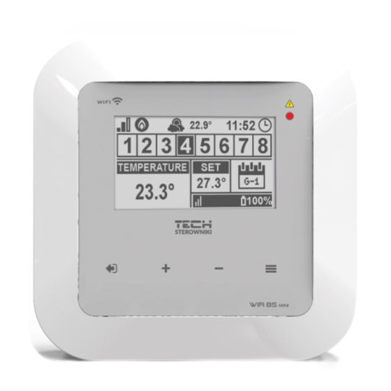
- Page 1 WiFi 8s mini...
-
Page 2: Table Of Contents
TABLE OF CONTENTS Safety ..................................4 Device description ..............................5 III. Principle of operation ..............................5 How to install the controller ............................. 6 First start-up ................................8 How to configure internet connection ........................8 How to configure the external sensor C-8ZR......................8 How to configure temperature sensor and room regulators ................... - Page 3 Software version ..............................19 How to control the heating system online ......................20 HOME tab ................................21 Zones tab ................................25 Statistics tab ................................25 Settings tab ................................26 Software update ..............................27 Technical data ................................27 XII. Protections and alarms ............................28 KN.2020.05.12...
-
Page 4: Safety
SAFETY Before using the device for the first time the user should read the following regulations carefully. Not obeying the rules included in this manual may lead to personal injuries or controller damage. The user’s manual should be stored in a safe place for further reference. -
Page 5: Device Description
III. PRINCIPLE OF OPERATION The WiFi 8s mini controller decides if a given zone needs to be heated on the basis of current temperature value sent by the room sensor or the room regulator, as well as the individual operation algorithm of the zone. If heating is necessary, the controller activates the voltage-free contact (or sends a signal via MW-1) which may be used e.g. -
Page 6: How To Install The Controller
IV. HOW TO INSTALL THE CONTROLLER The controller should be installed by a qualified person. WARNING Risk of fatal electric shock from touching live connections. Before working on the controller switch off the power supply and prevent it from being accidentally switched on. Remove the controller cover and connect the wires following the diagrams below and the connector labels. - Page 7 Connection with the MW-1 module: VER-CT VER-RP VER-RP230 heating device VER-CTZ VER-COO...
-
Page 8: First Start-Up
HOW TO CONFIGURE TEMPERATURE SENSOR AND R OOM REGULATORS To enable WiFi 8s mini to control a given zone, it is necessary to provide it with current temperature value. The easiest way is to use C-8r temperature sensor. If the user wants to be able to change the pre-set temperature value directly from the zone, it is advisable to use R-8B or R-8bw or R-8z room regulator. -
Page 9: How To Configure Wireless Thermostatic Actuators Stt-868/Stt-869
HOW TO CONFIGURE WINDOW SENSOR In order to register the sensor, go to WiFi 8s mini menu and select the number of zone where the sensor is to be registered. Next, select Window sensors/Registration and press quickly the communication button on the window sensor. Release the button and watch the control light: ... -
Page 10: Wireless Communication
VI. WIRELESS COMMUNICATION The WiFi 8s mini controller may communicate wirelessly with certain devices: Device Function Configuration C-8r - sending current room sensor should room temperature temperature readings registered in a given zone. sensor R-8b, R-8bw sending current zone The room regulator should be registered in a given zone. -
Page 11: Main Screen Description
MW-1 - offers the possibility of The module should be executive module establishing wireless registered in the controller. communication with the main controller or temperature sensor. VII. MAIN SCREEN DESCRIPTION Display EXIT – in the main screen view it is used to open up the screen view selection submenu (WiFi or Zones). In the controller menu it is used to cancel the settings and exit the submenu. - Page 12 MAIN SCREEN DESCRIPTION – ZONES 1. WiFi signal strength 2. Additional device icon – displayed when the device is switched on. 3. External temperature 4. Current time 5. Zone information: The displayed digit represents the room sensor sending current temperature readings from a given zone. In case of an alarm in a given zone, the screen displays an appropriate message.
- Page 13 MAIN SCREEN DESCRIPTION – WIFI 1. Day of the week 2. Current date 3. Current time 4. Signal strength 5. WiFi network name MAIN SCREEN DESCRIPTION - ZONE 1 1. WiFi signal strength 2. Current time 3. Current date 4.
-
Page 14: Controller Functions
VIII. CONTROLLER FUNCTIONS BLOCK DIAGRAM - MAIN MENU Registration Pre-set temparature Zones 1-8 Hysteresis Calibration Actuators Window sensors Registration External sensor Signal Battery Calibration Zones Voltage-free contact Activation delay Additional contact Alarms Voltage-free contact Fitter's menu Hreating Software version... -
Page 15: Zones 1-8
The Registration function is available for zones 1-8. 2.2. Once the room sensor has been switched on and registered in a given zone, its readings are used by the WiFi 8s mini controller. The sensor may be disabled by deselecting ON. -
Page 16: Window Sensors
Example: Pre-set zone temperature: 23˚C Minimum opening: 30% Maximum opening: 90% Range: 5˚C Hysteresis: 2˚C In the above example, the thermostatic valve starts closing at the temperature of 18˚C (pre-set value minus Range: 23-5). The minimum opening is reached when the zone temperature reaches the pre-set value. After reaching the pre-set value, the temperature starts falling. -
Page 17: External Sensor
It is possible to connect an external temperature sensor to the controller. The device enables the user to monitor current temperature on the main screen as well as via https://emodul.eu. Once the external sensor has been installed, it must be registered in the WiFi 8s mini controller – the registration process is described in detail in First start-up section. -
Page 18: Fitter's Menu
FITTER’S MENU WiFi network selections Internet module Network configuration Registration Time lock Protections Blocking time PIN code Automatic Time settings Time settings Date settings Screen view Display contrast Screen settings Screen brightness Language Screen blanking Service menu Screen blanking time Factory settings 6.1. -
Page 19: Protections
DHCP, IP address, Subnet mask, Gate address, DNS address and MAC address. REGISTRATION Select Registration in order to generate the code necessary to register the WiFi 8s mini controller at https://emodul.eu – see: First start-up. 6.2. -
Page 20: How To Control The Heating System Online
Once logged in, go to Settings tab and select Register module. Next, enter the code generated by the controller (to generate the code, select Registration in the WiFi 8s mini controller menu). The module may be assigned a name (in the... -
Page 21: Home Tab
HOME TAB Home tab displays the main screen with tiles illustrating the current status of particular heating system devices. Tap on the tile to adjust the operation parameters: HOME tab NOTE ‘No communication’ message means that the communication with the temperature sensor in a given zone has been interrupted. - Page 22 Tap on the tile corresponding to a given zone to edit its pre-set temperature The upper value is the current zone temperature whereas the bottom value is the pre-set temperature. The pre-set zone temperature depends by default on the weekly schedule settings. Constant temperature mode enables the user to set a separate pre-set temperature value which will apply in the zone regardless of the time.
- Page 23 Two types of weekly schedules are available in the WiFi 8s mini controller: 1. Local schedule It is a weekly schedule assigned to a particular zone. Once the WiFi 8s mini controller detects the room sensor, the schedule is assigned automatically to the zone. It may be edited by the user.
- Page 24 Editing a weekly schedule Editing enables the user to define two programs and select the days when the programs will be active (e.g. from Monday to Friday and the weekend). The starting point for each program is the pre-set temperature value. For each program the user may define up to 3 time periods when the temperature will be different from the pre-set value.
-
Page 25: Zones Tab
ZONES TAB The user may customize the home page view by changing the zone names and the corresponding icons. In order to do it, go to Zones tab. Zones tab STATISTICS TAB The Statistics tab enables the user to view the temperature charts for different time periods e.g. 24h, a week or a month. It is also possible to view the statistics for the previous months: An example chart... -
Page 26: Settings Tab
SETTINGS TAB The Settings tab enables the user to register a new module and change the e-mail address or the password: WiFi-8s mini Tech: WiFi-8s mini (v.2.1.227) WiFi-8s mini WiFi-8s mini Settings/Module tab Settings/Account tab... -
Page 27: Software Update
X. SOFTWARE UPDATE NOTE Software update shall be conducted only by a qualified fitter. After the software has been updated, it is not possible to restore previous settings. In order to install new software, the controller must be unplugged from the power supply. Next, insert the flash drive with the new software into the USB port. -
Page 28: Protections And Alarms
XII. PROTECTIONS AND ALARMS The device supports the following cases within a zone: Alarm Possible cause How to fix it - Place the sensor/regulator in a different place - No range - Insert batteries to the No communication with the - No batteries sensor/regulator sensor/wireless regulator... - Page 29 Error #3 - Calibration error 3 - The - The valve stroke is too small or the screw has not been pulled out valve dimensions are not typical - Replace the batteries enough - the screw meets resistance - Actuator current sensor is damaged - Call the service staff too early - Low battery level...
- Page 30 EU declaration of conformity Hereby, we declare under our sole responsibility that WiFi 8s mini manufactured by TECH, head-quartered in Wieprz Biała Droga 31, 34-122 Wieprz, is compliant with Directive 2014/53/EU of the European parliament and of the Council of 16 April 2014 on the harmonisation of the laws of the Member States relating to the making available on the market of radio equipment and repealing Directive 1999/5/EC (EU OJ L 153 of 22.05.2014, p.62), Directive 2009/125/EC of 21...
Need help?
Do you have a question about the WIFI 8S MINI and is the answer not in the manual?
Questions and answers