Table of Contents
Advertisement
Quick Links
Advertisement
Table of Contents

Related Manuals for Dahua 28DH-PFS4218-16ET-190-V3


Summary of Contents for Dahua 28DH-PFS4218-16ET-190-V3
- Page 1 PoE Switch (16/24-port Managed Desktop Switch) Quick Start Guide V1.0.1...
-
Page 2: Foreword
Foreword General This manual mainly introduces the hardware, installation, and wiring steps of the 16/24-port managed desktop switch (hereinafter referred to as "the Device"). Safety Instructions The following categorized signal words with defined meaning might appear in the manual. Signal Words Meaning Indicates a high potential hazard which, if not avoided, will result in death or serious injury. - Page 3 using the device. ● If there is any uncertainty or controversy, we reserve the right of final explanation.
-
Page 4: Important Safeguards And Warnings
Important Safeguards and Warnings This section introduces content covering the proper handling of the Device, hazard prevention, and prevention of property damage. Read carefully before using the Device, comply with the guidelines when using it, and keep the manual safe for future reference. Operating Requirements ●... - Page 5 ● Connect class I electrical appliances to a power socket with protective earthing. ● Do not block the ventilator of the device with objects, such as newspapers, table clothes or curtains. ● Do not put open flames, such as a lit candle, on the device. ●...
-
Page 6: Table Of Contents
Table of Contents Foreword ........................................I Important Safeguards and Warnings ............................III 1 Overview ........................................1 1.1 Introduction ....................................1 1.2 Features ......................................1 2 Port and Indicator ....................................2 2.1 Front Panel ....................................2 2.2 Rear Panel ...................................... 3 3 Installation ....................................... 4 4 Wiring ......................................... -
Page 7: Overview
1 Overview 1.1 Introduction The Device is a layer-2 commercial switch. It provides a high-performance switching engine and large buffer memory to ensure smooth video stream transmission. With a full-metal design, the Device has great heat dissipation capabilities on its shell surface, and is able to work in environments that range from –10 °C (14 °F) to +55 °C (+131 °F). -
Page 8: Port And Indicator
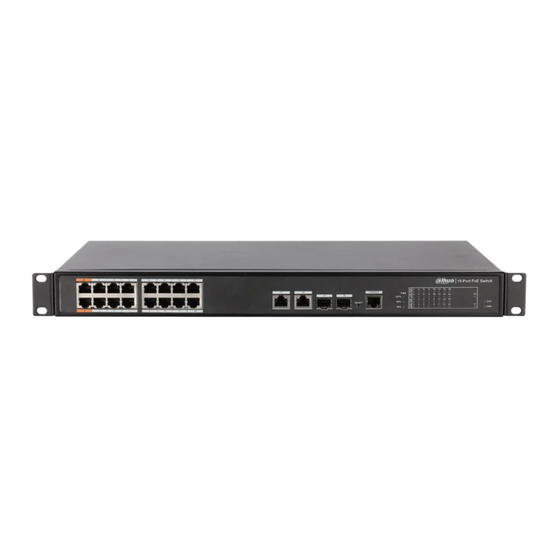
2 Port and Indicator 2.1 Front Panel The following figure is for reference only, and might differ from the actual device. Figure 2-1 Front panel Following are all the ports and indicators on the front panel of the 16/24-port managed desktop switch. -
Page 9: Rear Panel
2.2 Rear Panel The following figure is for reference only, and might differ from the actual device. Figure 2-2 Rear Panel Table 2-2 Description of the rear panel Description Power switch. Power port, supports 100–240 VAC. Ground terminal. -
Page 10: Installation
3 Installation The Device supports rack mount. Step 1 Attach the mounting bracket to the Device side panel (one on each side) and secure it with the screws provided with the rack. Figure 3-1 Install bracket Step 2 Attach the Device to the rack with screws. Figure 3-2 Install device... -
Page 11: Wiring
4 Wiring 4.1 Connecting GND Grounding the Device can protect it against lightning and interference. Step 1 Remove the ground screw from the Device and pass the ground screw through the round hole of the OT terminal of the ground cable. Turn the ground screw clockwise with a cross screwdriver to fasten the OT terminal of the ground cable. -
Page 12: Connecting Sfp Ethernet Port
Figure 4-3 Connect cable 4.4 Connecting SFP Ethernet Port ● When installing the SFP optical module, do not touch the gold finger of the SFP optical module. ● Do not remove the dust plug of the SFP optical module before connecting the optical fiber. ●... -
Page 13: Connecting Poe Ethernet Port
Figure 4-5 Connect optical fiber 4.5 Connecting PoE Ethernet Port If the terminal device has a PoE Ethernet port, you can directly connect this port to the Device PoE Ethernet port through the network cable to achieve synchronized network connection and power supply. -
Page 14: Quick Operation
5 Quick Operation 5.1 Login through Web You can log in to the Device through the web for management and operation. For details, see web operation manual. For first login, you need to change the password according to the interface prompt. Table 5-1 Default factory configuration Parameter Description... -
Page 15: Appendix 1 Cybersecurity Recommendations
Appendix 1 Cybersecurity Recommendations Mandatory actions to be taken for basic device network security: Use Strong Passwords Please refer to the following suggestions to set passwords: The length should not be less than 8 characters. Include at least two types of characters; character types include upper and lower case ... - Page 16 MAC Address Binding We recommend you to bind the IP and MAC address of the gateway to the device, thus reducing the risk of ARP spoofing. Assign Accounts and Privileges Reasonably According to business and management requirements, reasonably add users and assign a minimum set of permissions to them.
Need help?
Do you have a question about the 28DH-PFS4218-16ET-190-V3 and is the answer not in the manual?
Questions and answers