
Related Manuals for Marco M164-681-13


Summary of Contents for Marco M164-681-13
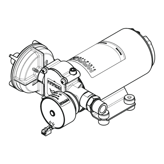
- Page 1 SELF-PRIMING ELECTRIC PUMP FOR TRANSFERRING VARIOUS LIQUIDS INSTRUCTIONS FOR USE 164 681 13-US - UP12/E 24V © S.p.A.
- Page 2 AIR VENT VALVE ACTIVATION When starting the pump, or when emptying the tank, slightly open the small valve in order to let the air out and facilitate the priming. As soon as the pump is operating close the small valve. ELECTRONIC PRESSURE SENSOR ©...
- Page 3 ELECTRONIC PRESSURE SENSOR WORKING DIRECTIONS The electronic pressure sensor, through the use of a microprocessor, controls the pump's speed to obtain the needed flow rate, with the following advantages: - Noise reduction during operation - The optimization of current consumption - A strong reduction of electrical noise, thanks to the slow speed ramp up and ramp down of the motor.
- Page 4 With fast flashing red LED, the pump is being overloaded (due to viscous liquids or gears overheating). While the pump is running, the speed is reduced to keep the current up to the nominal value for 30 seconds, period after which the circuit tries to release again the motor to its normal operating speed.
- Page 5 PRODUCT DESCRIPTION Self-priming gear pump, integrated check valve and electronic pressure sensor: to be used as automatic pump. Nickel-plated brass body, PTFE gears, stainless-steel shaft and lip seal. The electronic pressure sensor is preset at 50.8 psi. TECHNICAL DETAILS Tab.1 EN CODE TYPE VOLT...
-
Page 6: Ambient Conditions
AMBIENT CONDITIONS TEMPERATURE: min.-10°C 14°F-max.60°C 140°F RELATIVE HUMIDITY: max. 90 % WARNING: the above indicated temperature ranges are applicable to all components of the pump and these limits must be respected in order to avoid any possible damage or malfunctioning. OPERATING CYCLE The pump can operate on a continuous cycle with the following conditions: Ø... - Page 7 AMBIENT CONDITIONS TEMPERATURE: min.-10°C 14°F-max.60°C 140°F RELATIVE HUMIDITY: max. 90 % WARNING: the above indicated temperature ranges are applicable to all components of the pump and these limits must be respected in order to avoid any possible damage or malfunctioning. OPERATING CYCLE Under conditions of high operating pressures the pump can be subjected to elevated stresses and overheating and therefore should not be used for prolonged periods under such...
- Page 8 AMBIENT CONDITIONS TEMPERATURE: min.-10°C 14°F-max.60°C 140°F RELATIVE HUMIDITY: max. 90 % WARNING: the above indicated temperature ranges are applicable to all components of the pump and these limits must be respected in order to avoid any possible damage or malfunctioning. OPERATING CYCLE The pump can operate on a continuous cycle with the following conditions: Ø...
- Page 9 To ensure the correct directional flow of the fluid as indicated by the arrow on the top plate, it is necessary to connect the positive pole (+) of the battery supply to the red wire on the motor end-cap and the negative pole (-) to the black wire. Electrical connections must be made using adequate terminal blocks and connectors ensuring a tight fitment of the electrical cables.
-
Page 10: Troubleshooting
TROUBLESHOOTING CHECK POINTS IF THE PUMP HAS STOPPED OR WILL NOT START Ø Check the effectiveness of the battery power supply (voltage activity); Ø Check if the fuse has blown; Ø Check for any foreign matter present in the pump body. To do this, disconnect the power supply and unscrew the four fixing screws, remove the front cover plate and inspect the chamber. -
Page 11: Warranty
5) The Warranty does not cover any related installation costs involved. 6) Transport costs are refundable only in the case where warranty has been duly accepted by Marco Spa and they will be limited to the actual shipment costs between Marco Spa warehouse and the client's delivery address. - Page 12 EXPLODED VIEW © S.p.A.
- Page 13 DIMENSIONS © S.p.A.
- Page 14 DIAGRAMS FLOW RATE DIAGRAM 14,5 29,0 43,5 58,0 AMPERE-DRAW DIAGRAM 14,5 29,0 43,5 58,0 © S.p.A.
- Page 15 Requirements for household appliances, electric tools, and similar apparatus. Part 2: Immunity. This declaration is given under the sole responsibility of: MARCO S.P.A. Via Mameli 10 - 2501 Cas enedolo - Brescia - Italy Tel. 030/2134.1 Fax 030/2134.300 © S.p.A.
- Page 16 Property of MARCO S.p.A reproduction prohibited. All rights reserved. For further information visit our web site - www.marco.it Marco S.p.A Via Mameli 10 - 25014 Castenedolo (Brescia) – Italy tel. +39 030 2134.1 / Fax +39 030 2134.300...
Need help?
Do you have a question about the M164-681-13 and is the answer not in the manual?
Questions and answers