
Subscribe to Our Youtube Channel
Related Manuals for Marco UP12/E 12/24V


Summary of Contents for Marco UP12/E 12/24V
- Page 1 ELETTROPOMPA AUTOADESCANTE PER TRAVASO LIQUIDI SELF-PRIMING ELECTRIC PUMP FOR TRANSFERRING VARIOUS LIQUIDS AVVERTENZE D’USO INSTRUCTIONS FOR USE 164 681 15 - UP12/E 12/24V © S.p.A.
- Page 3 ATTIVAZIONE VALVOLA DI SFIATO / AIR VENT VALVE ACTIVATION Al primo avvio della pompa, oppure in caso di svuotamento del serbatoio, agire brevemente sulla valvola manuale per sfogare l’aria e favorire l’adescamento. E’ preferibile utilizzare almeno un primo tratto di tubazione flessibile in mandata della lunghezza minima di 1 m.
- Page 4 FUNZIONAMENTO DEL SENSORE DI PRESSIONE ELETTRONICO Il sensore di pressione elettronico, tramite l'utilizzo di un microprocessore, regola la portata richiesta variando proporzionalmente i giri del motore, ottenendo: Una riduzione del rumore durante il funzionamento. L'ottimizzazione dei consumi di corrente. Una riduzione netta dei disturbi elettrici, grazie ad una rampa di accelerazione graduale del motore.
- Page 5 Con led rosso lampeggiante velocemente, che la pompa è andata in sovraccarico (a causa di liquido troppo viscoso o surriscaldamento degli ingranaggi). La pompa viene rallentata fino a raggiungere l'assorbimento di corrente nominale, e rimane in questa condizione per 30 secondi, per poi tentare di ritornare alla condizione normale. Il circuito effettua 3 tentativi di ripristino prima di fermare definitivamente il motore, al quarto.
-
Page 6: Descrizione Del Dispositivo
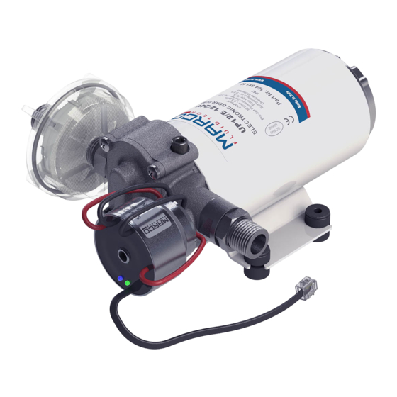
DESCRIZIONE DEL DISPOSITIVO Elettropompa autoadescante ad ingranaggi, valvola di non ritorno incorporata e sensore di pressione elettronico, per impiego come pompa automatica per sistemi ad acqua dolce. Corpo in ottone nichelato, ingranaggi in PTFE, albero in acciaio inossidabile e guarnizione a labbro.Il sensore di pressione viene tarato in fabbrica a 2,5 bar. -
Page 7: Condizioni Ambientali
CONDIZIONI AMBIENTALI ATTENZIONE: le temperature limite indicate si applicano ai componenti del dispositivo e devono essere rispettate per evitare possibili danneggiamenti o malfunzionamenti. Lo stoccaggio deve avvenire in luogo asciutto rispettando le medesime temperature. CICLO DI LAVORO In condizioni di massima pressione la pompa subisce sollecitazioni superiori, pertanto si consiglia di non utilizzarla per tempi prolungati in queste condizioni. - Page 8 Per la corretta direzione del flusso del liquido come indicato dalla freccia sulla parte superiore, è necessario collegare il polo positivo (+) della batteria al filo rosso che esce dalla calotta della pompa e il polo negativo (-), al filo nero. I collegamenti elettrici vanno eseguiti utilizzando morsettiere e connessioni adeguate con accurato serraggio dei conduttori.
-
Page 9: Problemi E Soluzioni
PROBLEMI E SOLUZIONI COSA VERIFICARE SE LA POMPA NON PARTE O SI ARRESTA? Ø Verificare l'efficienza del generatore (presenza di tensione) Ø Verificare se il fusibile è interrotto. Ø Verificare la presenza di corpi estranei nel corpo della pompa. Per effettuare ciò è necessario svitare le quattro viti di fissaggio, togliere il piattello di chiusura ed ispezionarne l'interno. -
Page 10: Garanzia
Marco S.p.A. Questi costi saranno limitati ai costi di spedizione tra il magazzino di Marco S.p.A. e la sede del cliente. 7) Nessuna nota di credito o reso sarà emessa prima di un test eseguito dal controllo di qualità... - Page 11 ELECTRONIC PRESSURE SENSOR WORKING DIRECTIONS The electronic pressure sensor, through the use of a microprocessor, controls the pump's speed to obtain the needed flow rate, with the following advantages: - Noise reduction during operation - The optimization of current consumption - A strong reduction of electrical noise, thanks to the slow speed ramp up and ramp down of the motor.
- Page 12 With fast flashing red LED, the pump is being overloaded (due to viscous liquids or gears overheating). While the pump is running, the speed is reduced to keep the current up to the nominal value for 30 seconds, period after which the circuit tries to release again the motor to its normal operating speed.
-
Page 13: Product Description
PRODUCT DESCRIPTION Self-priming gear pump, integrated check valve and electronic pressure sensor: to be used as automatic pump for water systems. Nickel-plated brass body, PTFE gears, stainless-steel shaft and lip seal. The electronic pressure sensor is preset at 2,5 bar. TECHNICAL DETAILS Tab.1 EN FUSE... -
Page 14: Ambient Conditions
AMBIENT CONDITIONS TEMPERATURE: min.-10°C 14°F-max.60°C 140°F RELATIVE HUMIDITY: max. 90 % WARNING: the above indicated temperature ranges are applicable to all components of the pump and these limits must be respected in order to avoid any possible damage or malfunctioning. OPERATING CYCLE Under conditions of high operating pressures the pump can be subjected to elevated stresses and overheating and therefore should not be used for prolonged periods under such... - Page 15 To ensure the correct directional flow of the fluid as indicated by the arrow on the top plate, it is necessary to connect the positive pole (+) of the battery supply to the red wire on the motor end-cap and the negative pole (-) to the black wire. Electrical connections must be made using adequate terminal blocks and connectors ensuring a tight fitment of the electrical cables.
-
Page 16: Troubleshooting
TROUBLESHOOTING CHECK POINTS IF THE PUMP HAS STOPPED OR WILL NOT START Ø Check the effectiveness of the battery power supply (voltage activity); Ø Check if the fuse has blown; Ø Check for any foreign matter present in the pump body. To do this, disconnect the power supply and unscrew the four fixing screws, remove the front cover plate and inspect the chamber. -
Page 17: Environmental Disposal
5) The Warranty does not cover any related installation costs involved. 6) Transport costs are refundable only in the case where warranty has been duly accepted by Marco Spa and they will be limited to the actual shipment costs between Marco Spa warehouse and the client's delivery address. - Page 18 SCHEDA DI ASSEMBLAGGIO / EXPLODED VIEW Pos. Q.tà Descrizione Pos. Q.tà Descrizione CORPO POMPA O-RING TIRANTE RACCORDO O-RING O-RING CARCASSA PIATTELLO INDOTTO VITE CALOTTA SENSORE DI PRESSIONE O-RING O-RING RONDELLA TAPPO DI SFIATO DADO RACCORDO VALVOLA DI NON RITORNO O-RING LINGUETTA PORTAGOMMA INGRANAGGIO TRAINANTE...
- Page 19 INGOMBRI / DIMENSIONS © S.p.A.
- Page 20 DIAGRAMMI / DIAGRAMS DIAGRAMMA PORTATA FLOW RATE DIAGRAM DIAGRAMMA ASSORBIMENTI AMPERE-DRAW DIAGRAM A (1 2 V ) A (2 4 V ) 0 ,5 1 ,5 2 ,5 b a r © S.p.A.
- Page 21 Confermiamo che il prodotto: We confirm that the product: 164 681 15 - UP12/E 12/24V Autoclave con controllo elettronico / Electronic Gear pump è conforme alla Direttiva 2014/30/UE (ex. 2004/108/CE) relativa alla compatibilità elettromagnetica e alla Direttiva 2006/42/CE relativa alle macchine.
- Page 22 NOTE / NOTES © S.p.A.
- Page 24 Questo documento e' proprieta' di Marco S.p.A la riproduzione e l'uso sono vietati. Tutti i diritti sono riservati. Per ulteriori informazioni vedere nostro sito internet - www.marco.it Marco S.p.A Via Mameli 10 - 25014 Castenedolo (Brescia) – Italia tel. +39 030 2134.1 / Fax +39 030 2134.300 Property of MARCO S.p.A reproduction prohibited.
Need help?
Do you have a question about the UP12/E 12/24V and is the answer not in the manual?
Questions and answers