Table of Contents
Advertisement
Quick Links
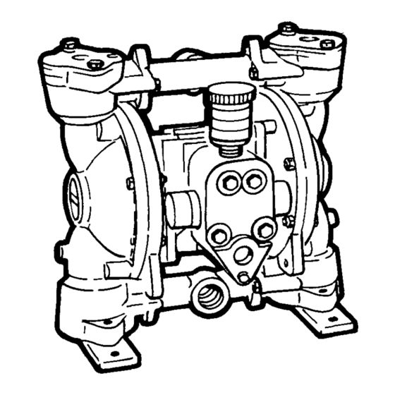
LINCOLN
Models
84852,
84853,
84855,
84856
1"AIR-POWERED
DIAPHRAGM
PUMP
Series "B"
OPERATING
AND
SERVICE
INSTRUCTIONS
HAZARD
WARNING
POSSIBLE
EXPLOSION
HAZARD
can result
if 1,1,1,
-Trichloroethane,
Methylene
Chloride
or other
Halogenated
Hydrocarbon
solvents
are used
in
pressurized
fluid
systems
having
Aluminum
or Galvanized
wetted
parts.
Death,
serious
bodily
injury
and/or
property
damage
could
result.
Consult
with
the
factory
if you
have
questions
concerning
Haloge-
nated
Hydrocarbon
solvents.
Do not use for pumping
flam-
mable
materials.
Build
up and
discharge
of
static
electricity
may
result
in a fire
and/or
ex-
plosion
causing
personal
injury
and
loss to property.
Principle
of Operation
The pump is powered
by compressed
air which
alternately
pressurizes
the
inner sides of the two diaphragm
cham-
bers while
simultaneously
exhausting
OPERATING
INSTRUCTIONS,
SERVICE
MANUAL
AND REPAIR PARTS LIST
the
opposite
inner
chambers
causing
the diaphragms,
which
are connected
by a shaft, to move endwise.
Since
air
pressure
is applied
over the entire
sur-
face of the diaphragm
which
is forcing
liquid to be discharged
by its other side,
the
diaphragm
is operating
under
a
balanced
condition
during
the
dis-
charge
stroke.
This allows
the unit to be
operated
at discharge
heads
over 200
feet (61 meters)
of water
head.
Alternate
pressurizing
and exhaust-
ing of the diaphragm
chamber
is per-
formed
by an externally
mounted,
pilot-
operated,
four way, spool type air distri-
bution
valve.
When
the spool
is at one
end of the valve body, inlet air pressure
is connected
to one diaphragm
cham-
ber and
the other diaphragm
chamber
is
connected
to the
exhaust.
When
the
spool
is moved
to the opposite
end of
the valve body, the porting
of chambers
is reversed.
The air distribution
valve
spool is moved from one end position
to
the other
in the valve body by means
of
an internal
pilot valve which
alternately
pressurizes
the ends of the air distribu-
tion
valve
spool
while
simultaneously
exhausting
the
other
ends.
The pilot
valve is positively
shifted
at each end of
the diaphragm
stroke
by the diaphragm
plate's coming
in contact
with the end of
the pilot valve spool
and pushing
it into
position
for shifting
of the air distribu-
tion
valve.
The
chambers
are
mani-
folded
together
with a suction
and dis-
charge
check valve for each chamber
to
maintain
flow
in one direction
through
the pump.
INSTALLATION
PROCEDURES
Position
the pump as close as possi-
ble to the
source
of the
liquid
to be
pumped.
Avoid
long or undersize
suc-
tion lines and use the minimum
number
of fittings.
For permanent
installation
involving
rigid
piping,
install
short
flexible
sec-
tions
of hose
between
the
pump
and
piping.
This
reduces
strains
and per-
mits
easier
removal
of the
pump
for
service
when required.
At time
of insta-
llation,
inspect
all external
gasketed
fasteners
for
looseness
caused
by
gasket
creep.
Tighten
loose
fittings
securely
to prevent
leakage.
AIR SUPPLY
Do not
connect
the
unit
to an air
supply
in excess
of 125 PSI (8 61 bars).
Install
a shutoff
valve
in the air supply
line
to permit
removal
of the
unit
for
servicing.
When
connecting
an air sup-
ply of rigid
piping,
mount
a section
of
flexible
line
to the
pump
to eliminate
piping
strain.
In permanent
installa-
tions,
an air line filter
IS recommended.
The weight
of the air supply
line
and
of the
filter
must
be supported
by
some
means
other
than
the air valve
cap.
Failure
to provide
support
may
result
in damage
to
the
pump.
A
pressure
regulating
valve
should
be
installed
to
prevent
pressure
from
exceeding
recommended
limits.
OPERATION
Your pump
has been tested
prior to
shipment
and is ready for use as received
It is completely
self-priming
and no ini-
tial filling
with fluid
is required.
If the unit is to be totally
submerged,
the
air exhaust
must
be piped
above
liquid
level
to prevent
the
liquid
and
foreign
material
from
entering
the air
distribution
valve mechanism.
Open
the inlet air valve at least one
turn to allow
sufficient
cycling
rate for
the pump to prime (30 to 60 cycles
per
minute).
After
pumping
starts,
adjust
the inlet air valve for the desired
pump
ing capacity.
When
further
opening
of
the inlet air valve
increases
cycling
rate
without
increasing
the
flow
rate,
the
pump
is being
starved
of liquid
due to
suction
limitations.
Further
opening
of
the air inlet
valve will waste compressed
air.
Set
the
inlet
air valve
for lowest
cycling
rate that does not decrease
flow
rate for most efficient
operation.
LINCOLN
Section
-
B5
Page
-
15D
FEB-95
FORM 402581
Advertisement
Table of Contents


Need help?
Do you have a question about the 84852 and is the answer not in the manual?
Questions and answers