Table of Contents
Advertisement
Quick Links
CAUTION! Risk of Fire! DO NOT store instruction manuals inside fireplace cavity.
High temperatures could cause a fire.
INSTALLER: Leave this manual with the appliance, not inside the appliance.
CONSUMER: Retain this manual for future reference. Do not store inside the appliance.
NOTICE: DO NOT discard this manual!
Models:
NOTE: NOT INTENDED FOR
NOTE:
FIREPLACE INSERT.
Decorative barrier front must be ordered separately at
time of appliance purchase. See Section 3.B.
DO NOT PLACE ARTICLES ON OR AGAINST THIS APPLIANCE.
DO NOT USE OR STORE FLAMMABLE MATERIALS NEAR THIS APPLIANCE.
DO NOT SPRAY AEROSOLS IN THE VICINITY OF THIS APPLIANCE WHILE IT IS IN OPERATION.
DO NOT MODIFY THIS APPLIANCE.
Installation Manual
Installation and Appliance Setup
Ref No GMK10810
AS/NZS 5263.1.8
Heat & Glo • 6KX-AU Installation Manual • 2589-980 Rev. B • 5/23
WARNING:
FIRE OR EXPLOSION HAZARD
Failure to follow safety warnings exactly
could result in serious injury, death, or
property damage.
• DO NOT store or use gasoline or other flam-
mable vapors and liquids in the vicinity of this
or any other appliance.
• What to do if you smell gas
- DO NOT try to light any appliance.
- DO NOT touch any electrical switch. DO
NOT use any phone in your building.
- Leave the building immediately.
- Immediately call your gas supplier from
a neighbor's phone. Follow the gas sup-
plier's instructions.
- If you cannot reach your gas supplier, call
the fire department.
• Installation and service must be performed
by a qualified installer, service agency, or the
gas supplier.
DANGER
DO NOT TOUCH GLASS
NEVER ALLOW CHILDREN
A barrier designed to reduce the risk of
burns from the hot viewing glass is provided
with this appliance and shall be installed for
the protection of children and other at-risk
individuals.
HOT GLASS WILL
CAUSE BURNS.
UNTIL COOLED.
TO TOUCH GLASS.
1
Advertisement
Table of Contents

Subscribe to Our Youtube Channel
Related Manuals for Heat & Glo 6KX-AU


Summary of Contents for Heat & Glo 6KX-AU
- Page 1 DO NOT USE OR STORE FLAMMABLE MATERIALS NEAR THIS APPLIANCE. DO NOT SPRAY AEROSOLS IN THE VICINITY OF THIS APPLIANCE WHILE IT IS IN OPERATION. DO NOT MODIFY THIS APPLIANCE. Heat & Glo • 6KX-AU Installation Manual • 2589-980 Rev. B • 5/23...
-
Page 2: Table Of Contents
B. Accessories ........83 = Contains updated information. Heat & Glo • 6KX-AU Installation Manual • 2589-980 Rev. B • 5/23... -
Page 3: Installation Standard Work Checklist
_____________________________________________________________________________________ _________________________________________________________________________________________________ _________________________________________________________________________________________________ Comments Communicated to party responsible ____________________ by ______________________on ___________ (Builder / Gen. Contractor/) (Installer) (Date) = Contains updated information. 2589-982B 5/23 Heat & Glo • 6KX-AU Installation Manual • 2589-980 Rev. B • 5/23... -
Page 4: Product Specific And Important Safety Information
* The allowable Outlet (Manifold) Gas Pressure ranges are: Natural Gas .78 - .95 kPa (.78 kPa nominal) and Propane, ULPG 2.37 - 2.61 kPa (2.44 kPa nominal). Certification testing setpoint values are shown. Heat & Glo • 6KX-AU Installation Manual • 2589-980 Rev. B • 5/23... -
Page 5: High Altitude Installations
G. Electrical Codes All electrical safety testing has been done following the EN 60335-2-102 standard. Local codes apply. Heat & Glo • 6KX-AU Installation Manual • 2589-980 Rev. B • 5/23... -
Page 6: Getting Started
6 in. (152 mm) MEASUREMENTS FROM TOP EDGE OF THE OPENING APPLIANCE FRONT Figure 2.3 Good Faith Wall Surface Temperatures Above Appliance With Passive Heat Kit Installed Heat & Glo • 6KX-AU Installation Manual • 2589-980 Rev. B • 5/23... - Page 7 Sugges�ons on how to further reduce TV temperatures: Increase “A” dimension. b. Increase “C” dimension, however, increasing “B” dimension beyond maximum recommended typically results in higher temperatures. Figure 2.4 Good Faith TV Guidelines Heat & Glo • 6KX-AU Installation Manual • 2589-980 Rev. B • 5/23...
- Page 8 Increase “A” dimension. b. Increase “C” dimension, however, increasing “B” dimension beyond maximum recommended typically results in higher temperatures. Figure 2.5 Good Faith Guidelines - Passive Heat Kit Installed Heat & Glo • 6KX-AU Installation Manual • 2589-980 Rev. B • 5/23...
-
Page 9: Tools And Supplies Needed
• Improper positioning of the logs/media (as applicable) or the glass assembly. • Installation and/or use of any component part not approved by Hearth & Home Technologies. Heat & Glo • 6KX-AU Installation Manual • 2589-980 Rev. B • 5/23... -
Page 10: Framing And Clearances
1041 8-1/2 38-5-16 11-3/16 26-7/8 21-7/16 34-5/8 41-3/4 1060 8-1/2 24-3/4 14-1/4 34-1/4 8-1/2 33-1/2 39-13/16 1011 6-3/8 40-7/8 1038 28-3/8 1-1/4 6-3/8 Figure 3.1 Appliance Dimensions Heat & Glo • 6KX-AU Installation Manual • 2589-980 Rev. B • 5/23... -
Page 11: Decorative Barrier Front Dimension Diagrams
12 In. (305 mm) Mantel Depth at 12 In. (305 mm) Mantel Depth (No Passive Heat) with Passive Heat Installed 1-1/8 LOFT-6 Figure 3.2 Decorative Barrier Front Dimensions - LOFT Heat & Glo • 6KX-AU Installation Manual • 2589-980 Rev. B • 5/23... - Page 12 12 In. (305 mm) Mantel Depth at 12 In. (305 mm) Mantel Depth (No Passive Heat) with Passive Heat Installed 1-1/8 FORGE-6 Figure 3.3 Decorative Barrier Front Dimensions - FORGE Heat & Glo • 6KX-AU Installation Manual • 2589-980 Rev. B • 5/23...
- Page 13 12 In. (305 mm) Mantel Depth at 12 In. (305 mm) Mantel Depth (No Passive Heat) with Passive Heat Installed 1-1/8 CHAPEL-6 Figure 3.4 Decorative Barrier Front Dimensions - CHAPEL Heat & Glo • 6KX-AU Installation Manual • 2589-980 Rev. B • 5/23...
- Page 14 12 In. (305 mm) Mantel Depth at 12 In. (305 mm) Mantel Depth (No Passive Heat) with Passive Heat Installed 1-1/8 FOLIO-6 Figure 3.5 Decorative Barrier Front Dimensions - FOLIO Heat & Glo • 6KX-AU Installation Manual • 2589-980 Rev. B • 5/23...
-
Page 15: Appliance Location And Clearances To Combustibles
Actual installation may vary due to individual design preference. Figure 3.6 Clearance for Heat Management System HEAT-ZONE -240-V ® KNOCKOUT LOCATIONS Figure 3.7 Heat Management Knockout Locations Heat & Glo • 6KX-AU Installation Manual • 2589-980 Rev. B • 5/23... - Page 16 See Section 10 17-3/4 For terminations 80-1/8 6KX-AU Mantel through a 2 x 4 wall, 1295 1067 1829 1438 2035 Projections see Figure 3.10. Figure 3.8 Appliance Locations Heat & Glo • 6KX-AU Installation Manual • 2589-980 Rev. B • 5/23...
- Page 17 WALL SHEATHING (89 mm) INTERIOR SHEATHING 1/2 IN. (13 mm) THICK DVP90ST 5 IN. (127 mm) Figure 3.9 DVP-TRAP1 Exception (2 x 4 (51 x 102 mm) Construction) Heat & Glo • 6KX-AU Installation Manual • 2589-980 Rev. B • 5/23...
- Page 18 C** Add 12 in. (305 mm) for rear venting with one 90 degree elbow. G*** For installations with vinyl flooring, see Section 3.E. Figure 3.10 Clearances to Combustibles Heat & Glo • 6KX-AU Installation Manual • 2589-980 Rev. B • 5/23...
- Page 19 3 in. (76 mm), wire mesh is required. Figure 3.11 Passive Heat Front Discharge Framing Dimensions With and Without a Trim Kit Heat & Glo • 6KX-AU Installation Manual • 2589-980 Rev. B • 5/23...
- Page 20 Combustible Opening Opening Bottom of Appliance Bottom of Appliance Materials Inches 12-1/4 8-3/4 68-1/4 83-1/2 6KX-AU millimeters 1734 2121 Figure 3.12 Passive Heat Side Discharge Framing Dimensions Heat & Glo • 6KX-AU Installation Manual • 2589-980 Rev. B • 5/23...
- Page 21 Mesh screen required for front discharge or open top discharge passive heat installations with discharge opening of 3 inches or greater. Figure 3.13 Passive Heat Minimum Framing Dimensions Open Top Discharge Heat & Glo • 6KX-AU Installation Manual • 2589-980 Rev. B • 5/23...
-
Page 22: Constructing The Appliance Chase
Minimum height requirements for an exterior chase on a top- vented appliance are shown in Figure 3.14. Reference Fig- ure 4.5 for additional clearances. Heat & Glo • 6KX-AU Installation Manual • 2589-980 Rev. B • 5/23... -
Page 23: Floor Protection
FLOORING OR HEARTH MATERIAL ALLOWED UP TO TOP OF BOTTOM SURROUND See Detail A Front View Figure 3.16 Flooring & Hearth Material Allowed Figure 3.15 Vinyl Flooring Recommendations Heat & Glo • 6KX-AU Installation Manual • 2589-980 Rev. B • 5/23... -
Page 24: Termination Location And Vent Information
Over 56.3° to 59.0°..........2290 59.0° to 60.3°............2440 * H minimum may vary depending on regional snowfall. Refer to local codes. Figure 4.1 Minimum Height From Roof to Lowest Discharge Opening Heat & Glo • 6KX-AU Installation Manual • 2589-980 Rev. B • 5/23... - Page 25 • Measure horizontal and vertical termination cap clearances as noted in Figure 4.3 and 4.4. H=Measure Horizontal Distances from H V=Measure Vertical Distances from V Figure 4.3 Heat & Glo • 6KX-AU Installation Manual • 2589-980 Rev. B • 5/23...
-
Page 26: Chimney Diagram
500 mm of the opening and discharging in the direction of the opening. 4. Clearance from a flue terminal to a LP cylinder shall be a minimum of 1 meter. MINIMUM CLEARANCES REQUIRED FOR BALANCED FLUE TERMINALS OR THE FLUE TERMINALS OF OUTDOOR APPLIANCES Figure 4.5 Minimum Clearances for Termination Heat & Glo • 6KX-AU Installation Manual • 2589-980 Rev. B • 5/23... -
Page 27: Use Of Elbows
Figure 4.7 Vertical and Horizontal Offset for DVP and SLP Elbows DVP36 25-1/2 DVP48 1219 DVP6A 3 to 6 76 to 152 2-1/8-4-1/4 54-108 DVP12A 3 to 12 76 to 305 2-1/8-8-1/2 54-216 Figure 4.6 Heat & Glo • 6KX-AU Installation Manual • 2589-980 Rev. B • 5/23... -
Page 28: Vent Diagrams
• 2 x 45° elbow jog directly off the top of the fireplace is allowed but has no V or H value and DOES NOT count towards total elbow count. 1/4 in. max. (6 mm) Figure 4.8 Heat & Glo • 6KX-AU Installation Manual • 2589-980 Rev. B • 5/23... - Page 29 • Horizontal pipe installed level with no rise. MEASURE TO SHADED SURFACE (OUTSIDE MOUNTING SURFACE) Figure 4.9 Measure to Outside Mounting Surface Figure 4.10 Measure to Top of Last Section of Pipe Heat & Glo • 6KX-AU Installation Manual • 2589-980 Rev. B • 5/23...
- Page 30 HORIZONTAL PIPE SUPPORT PIPE LENGTH WALL FIRESTOP 90 DEGREE ELBOW CEILING WALL BRACKET FIRESTOP Flue system termination kits DVP-SERIES DVP-TVHW DVP-TRAP2 Figure 4.11 Flue Components and Terminations Heat & Glo • 6KX-AU Installation Manual • 2589-980 Rev. B • 5/23...
- Page 31 6.1 m = 40 ft. (12.2 m) Maximum = 10 ft. (3.0 m) Maximum = 40 ft. (12.2 m) Maximum = 20 ft. (6.1 m) Maximum Figure 4.12 Heat & Glo • 6KX-AU Installation Manual • 2589-980 Rev. B • 5/23...
- Page 32 = 40 ft. (12.2 m) Maximum = 11 ft. (3.4 m) Maximum = 40 ft. (12.2 m) Maximum = 20 ft. (6.1 m) Maximum INSTALLED HORIZONTALLY Figure 4.13 Heat & Glo • 6KX-AU Installation Manual • 2589-980 Rev. B • 5/23...
- Page 33 1.2 m 8 ft. 2.4 m 4 ft. 1.2 m 8 ft. 2.4 m = 16 ft. (4.9 m) Maximum = 40 ft. (12.2 m) Maximum Figure 4.14 Heat & Glo • 6KX-AU Installation Manual • 2589-980 Rev. B • 5/23...
- Page 34 = 3 ft. Min. (914 mm) Note: If installing a vertical vent/ termination off the top of the ap- pliance, the flue restrictor should be used. Figure 4.15 Heat & Glo • 6KX-AU Installation Manual • 2589-980 Rev. B • 5/23...
- Page 35 HOLES TO THE RIGHT TO BREAK APART BEND HERE ALWAYS USED WITH THE FLUE RESTRICTOR SET TO 4-4 HOLES TO THE RIGHT Figure 4.17 Setting the Flue Restrictor Heat & Glo • 6KX-AU Installation Manual • 2589-980 Rev. B • 5/23...
- Page 36 = 18 ft. (5.5 m) Maximum = 40 ft. (12.2 m) Maximum * No specific restrictions on this value EXCEPT V cannot exceed 40 ft. (12.2 m). INSTALLED HORIZONTALLY Figure 4.19 Heat & Glo • 6KX-AU Installation Manual • 2589-980 Rev. B • 5/23...
- Page 37 Maximum (ULPG) 6KX-AU 12 in. (305 mm) Figure 4.20 One 45º Elbow Do not use a 45º elbow in corner installations. Use two 90º elbows instead. Figure 4.21 Heat & Glo • 6KX-AU Installation Manual • 2589-980 Rev. B • 5/23...
- Page 38 17 ft. 5.2 m 20 ft. 6.1 m = 40 ft. (12.2 m) Maximum = 3 ft. (914 mm) Maximum = 20 ft. (6.1 m) Maximum Figure 4.23 Heat & Glo • 6KX-AU Installation Manual • 2589-980 Rev. B • 5/23...
- Page 39 12 ft. 3.7 m 8 ft. 2.4 m 15 ft. 4.6 m = 40 ft. (12.2 m) Maximum = 15 ft. (4.6 m) Maximum INSTALLED HORIZONTALLY Figure 4.25 Heat & Glo • 6KX-AU Installation Manual • 2589-980 Rev. B • 5/23...
- Page 40 = 40 ft. (12.2 m) Maximum *No specific restrictions on this value EXCEPT cannot exceed 40 ft. (12.2 m) Maximum = 8 ft. (2.4 m) Maximum INSTALLED HORIZONTALLY Figure 4.27 Heat & Glo • 6KX-AU Installation Manual • 2589-980 Rev. B • 5/23...
-
Page 41: Power Vent Configurations
(6.10 m) (9.14 m) (12.19 m) (15.24 m) (18.29 m) (21.34 m) (24.38 m) (27.43 m) ALLOWABLE VENT RUNS ALLOWED Table 4.28 Allowable Vent Runs - Horizontal Termination Heat & Glo • 6KX-AU Installation Manual • 2589-980 Rev. B • 5/23... -
Page 42: Vent Clearances And Framing
The shield should be centered directly above the elbow, and positioned so that it cre- ates a 1/2 in. (13mm) airspace between the shield and the combustible surface. See Figure 5.2. Heat & Glo • 6KX-AU Installation Manual • 2589-980 Rev. B • 5/23... -
Page 43: Wall Penetration Framing/Firestops
Note: Center of the horizontal vent pipe to the vertical measuring surface of a trap cap is 5 inches (127 mm). Figure 5.4 Wall Penetration Heat & Glo • 6KX-AU Installation Manual • 2589-980 Rev. B • 5/23... -
Page 44: Ceiling Firestop/Floor Penetration Framing
INSTALL ATTIC INSULATION SHIELDS BEFORE OR AFTER INSTALLATION OF VENT SYSTEM CEILING FIRESTOP CEILING FIRESTOP INSTALLED BELOW CEILING INSTALLED ABOVE CEILING Figure 5.6 Installing the Attic Shield Heat & Glo • 6KX-AU Installation Manual • 2589-980 Rev. B • 5/23... -
Page 45: Appliance Preparation
Covering the Seal Cap mm) to hold outer pipe sections together. If predrilling holes, DO NOT penetrate inner pipe. Figure 6.3 (Generic Appliance Shown) Remove the seal cap. Heat & Glo • 6KX-AU Installation Manual • 2589-980 Rev. B • 5/23... - Page 46 DO NOT penetrate inner pipe. REMOVE SEAL CAP SEAL CAP STRAPS Figure 6.9 Remove Seal Cap NOTICE: Once the seal cap has been removed it CANNOT be reattached. Heat & Glo • 6KX-AU Installation Manual • 2589-980 Rev. B • 5/23...
-
Page 47: Prepare For Heat Management
Reference the appropriate instructions included with the PASSIVE HEAT ADAPTER kit for the remaining installation steps. KNOCKOUTS PASSIVE HEAT FRONT COVER KNOCKOUT Figure 6.12 Heat Management Knockout Locations Heat & Glo • 6KX-AU Installation Manual • 2589-980 Rev. B • 5/23... -
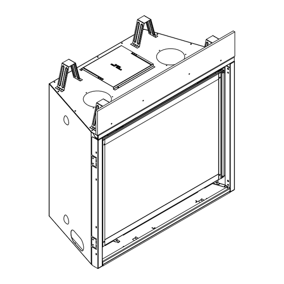
Page 48: Securing And Leveling The Appliance
DO NOT REMOVE NAILING TABS (BOTH SIDES) Figure 6.15 Non-Combustible Board - Studio Decorative Barrier Front Shown Figure 6.13 Proper Positioning and Securing of an Appliance Heat & Glo • 6KX-AU Installation Manual • 2589-980 Rev. B • 5/23... -
Page 49: Venting
• Only outer pipes need to be sealed. All unit collar, pipe, slip section, elbow and cap outer flues shall be sealed in this manner, unless otherwise stated. Figure 7.3 Figure 7.2 Heat & Glo • 6KX-AU Installation Manual • 2589-980 Rev. B • 5/23... -
Page 50: Assemble Slip Sections
“Assembling Pipe Sections.” NOTICE: If slip section is too long, the inner and outer flues of the slip section can be cut to the desired length. Heat & Glo • 6KX-AU Installation Manual • 2589-980 Rev. B • 5/23... -
Page 51: Secure The Vent Sections
• Wall shield firestops may be used to provide horizontal support to vent sections. 120º Figure 7.10 Align and Disassemble Vent Sections Figure 7.7 Securing Vertical Pipe Sections 120º Figure 7.8 Securing Horizontal Pipe Sections Heat & Glo • 6KX-AU Installation Manual • 2589-980 Rev. B • 5/23... -
Page 52: Vertical Termination Requirements
Slide the storm collar onto the exposed pipe section and align brackets. • Insert a bolt (provided) through the brackets and install nut. Do not completely tighten. Figure 7.13 Heat & Glo • 6KX-AU Installation Manual • 2589-980 Rev. B • 5/23... -
Page 53: Horizontal Termination Requirements
Important Notice: Heat shields may not be field constructed. SLIP SECTION CAN BE EXTENDED INNER VENT SHEATHING OUTER VENT INTERIOR EXTERIOR Figure 7.14 Venting Through the Wall Heat & Glo • 6KX-AU Installation Manual • 2589-980 Rev. B • 5/23... -
Page 54: Electrical Information
Wiring for optional Hearth & Home Technologies approved accessories should be done now to avoid reconstruction. Follow instructions that come with those accessories. Heat & Glo • 6KX-AU Installation Manual • 2589-980 Rev. B • 5/23... -
Page 55: Wiring Requirements
RED WIRE BLACK WIRE GREEN WIRE BATTERY PACK ORANGE WIRE 2166-323 GROUND LED CONTROL 2326-114 2589-160 EMBER LIGHTING 2583-061 Figure 8.1 IntelliFire Plus Wiring Diagram with Remote ® Heat & Glo • 6KX-AU Installation Manual • 2589-980 Rev. B • 5/23... -
Page 56: Service For Fan
• Reinstall valve plate assembly, burner assembly, base pan assembly, logs, appliance glass and decora- tive barrier front. FAN INSTALLED Figure 8.2 Fan Installed in Valve Plate Cavity Heat & Glo • 6KX-AU Installation Manual • 2589-980 Rev. B • 5/23... -
Page 57: Gas Information
• Verify inlet pressures. Verify minimum pressures when other household gas appliances are operating. • Install regulator upstream of valve if line pressure is greater than 3.40 KPa. Heat & Glo • 6KX-AU Installation Manual • 2589-980 Rev. B • 5/23... -
Page 58: High Altitude Installations
GAS CONNECTION orange with dark, smoky tips, provide more primary air to AND SERVICE ACCESS the burner by opening the air shutter accordingly. Figure 9.1 Bottom Surround Removal Heat & Glo • 6KX-AU Installation Manual • 2589-980 Rev. B • 5/23... -
Page 59: Service/Replace Appliance Gas Valve
* As tested 3 ft. (914 mm) out of rear vent, 90 degree verticle elbow, 2 ft. (610 mm) horizontal, 90 degree hori- zontal elbow, 1 ft. (309 mm) horizontal and a DVP-TRAP2 termination cap. Heat & Glo • 6KX-AU Installation Manual • 2589-980 Rev. B • 5/23... -
Page 60: Finishing
REQUIRED AIR FLOW GAP Flooring & Hearth Material (1-1/8 IN. MAX.) (29 mm) Figure 10.3 Required Air Flow Gap NO GAP ALLOWED Figure 10.1 Finishing Material Installed Heat & Glo • 6KX-AU Installation Manual • 2589-980 Rev. B • 5/23... -
Page 61: Installing A Television
Figure 10.3 Minimum Vertical and Maximum Horizontal NOT the top of the appliance. Dimensions of Combustibles or Painted Surfaces Figure 10.5 Minimum Vertical and Maximum Horizontal Dimensions of Non-Combustibles Heat & Glo • 6KX-AU Installation Manual • 2589-980 Rev. B • 5/23... - Page 62 ____, then maximum is_____. 0-7-7/16 7-7/16 Inches 0-189 Millimeters ∞ Inches ∞ Millimeters Figure 10.8 Non-Combustible Mantel Leg or Wall Projections (Acceptable on both sides of opening) Heat & Glo • 6KX-AU Installation Manual • 2589-980 Rev. B • 5/23...
- Page 63 8-3/4 IN. (222 mm) REGISTER COVER SLOTS FACE FRONT OF APPLIANCE 12-1/4 IN. (311 mm) Figure 10.9 Finishing Material installed with Passive Heat Optional Heat Management System Heat & Glo • 6KX-AU Installation Manual • 2589-980 Rev. B • 5/23...
-
Page 64: Hearth Extension
DECORATIVE BARRIER FRONT NON-COMBUSTIBLE FINISHING MATERIAL (TOP EDGE) Finishing materials 1 in. maximum thick. Stop finishing material flush with opening. Figure 10.11 Overlap Fit Decorative Barrier Front Heat & Glo • 6KX-AU Installation Manual • 2589-980 Rev. B • 5/23... - Page 65 Figure 10.12 Non-Combustible Finishing Material 1 In. (25 mm) thickness. Stop finishing material flush with appliance opening. Thick or Less - Overlap Fit Fronts Figure 10.13 Inside Fit Method Heat & Glo • 6KX-AU Installation Manual • 2589-980 Rev. B • 5/23...
- Page 66 NON-COMBUSTIBLE NON-COMBUSTIBLE FINISHING MATERIAL FINISHING MATERIAL DECORATIVE FRONT Figure 10.15 Install Finishing Strips Figure 10.14 Non-Combustible Finishing Material Thickness Greater Than One Inch - Finishing Strips Required Heat & Glo • 6KX-AU Installation Manual • 2589-980 Rev. B • 5/23...
- Page 67 NOTE: The TV installation requirements are the same regardless of whether the Passive Heat kit is installed with a top discharge, side discharge or open top discharge. Figure 10.16 Good Faith Guidelines for TV Installations Above a Fireplace with Passive Heat Option Heat & Glo • 6KX-AU Installation Manual • 2589-980 Rev. B • 5/23...
-
Page 68: Appliance Setup
BEND ALL TABS 90 DEGREES 36 INCH MODELS: 7 36 INCH MODELS: BEND AT PERFORATION AND REMOVE Figure 2 Back Refractory Support Figure 1 Side Refractory Bracket Heat & Glo • 6KX-AU Installation Manual • 2589-980 Rev. B • 5/23... - Page 69 Figure 5. Figure 7 Rear Glass Panel and Side Insulation Board Installed BACK REFRACTORY BACK REFRACTORY SUPPORT SUPPORT Figure 5 Back Insulation Board Installed Heat & Glo • 6KX-AU Installation Manual • 2589-980 Rev. B • 5/23...
- Page 70 INSULATION BOARD (WHITE) Figure 10 Bend Side Refractory Bracket Tabs REFRACTORY SUPPORT INSTALLED Figure 8 Install Side Refractory Bracket with Side Insulation Board and Side Glass Panel Heat & Glo • 6KX-AU Installation Manual • 2589-980 Rev. B • 5/23...
- Page 71 17. Install decorative front according to instructions included with decorative front. Figure 12 Top Refractory Installed 14. Set new base refractory pieces in place as shown Figure 13. 2581-937 Heat & Glo • 6KX-AU Installation Manual • 2589-980 Rev. B • 5/23...
-
Page 72: Install The Burner Overlay
BURNER OVERLAY FOR BURNER OVERLAY BURNER OVERLAY BURNER OVERLAY DETAIL BLOCKED PORT PARTIALLY OPEN PORT BLOCKED PORT Figure 11.2 Burner Overlay Installed Figure 11.1 Check Burner Ports Heat & Glo • 6KX-AU Installation Manual • 2589-980 Rev. B • 5/23... -
Page 73: Illuminated Embers
The embers provided should be enough for 3 to 5 applications. Apply embers here for smooth lighting characteristics. = NO EMBERS Figure 11.4 Burner Media / Ember Placement Heat & Glo • 6KX-AU Installation Manual • 2589-980 Rev. B • 5/23... -
Page 74: Install The Log Assembly
FLAT AREA FOR LOG 3 LOG STOP LOG STOP LOG PIN LOG PIN LOG SHELF RETURN BEND LOG SHELF RETURN BEND Figure 3 Place Log #1 Figure 4 Place Log #2 Heat & Glo • 6KX-AU Installation Manual • 2589-980 Rev. B • 5/23... - Page 75 DETAIL ON FIBER BURNER OVERLAY BUMP DETAIL BUMP DETAIL Figure 7 Install Log #4 Figure 8 Log Placement Details NOTCH NOTCH Figure 9 Bottom View of Log #4 Heat & Glo • 6KX-AU Installation Manual • 2589-980 Rev. B • 5/23...
- Page 76 Figure 11 Install Log #6 Figure 10 Install Log #5 Service Parts List Log # PART NUMBER SRV2582-700 SRV2582-701 SRV2582-702 SRV2582-703 SRV2582-704 SRV2582-705 Figure 12 Log Set Installed Heat & Glo • 6KX-AU Installation Manual • 2589-980 Rev. B • 5/23...
-
Page 77: Fixed Glass Assembly Removal And Replacement
• Reinstall decorative barrier front. LATCHES (BOTH BOTTOM GLASS FRAME AND TOP) TABS GLASS ASSEMBLY Figure 11.5 Fixed Glass Assembly Heat & Glo • 6KX-AU Installation Manual • 2589-980 Rev. B • 5/23... -
Page 78: Reference Materials
(508 MM) 6 in. (152 mm) 14 IN. (356 MM) 12 IN. (305 MM) DVP-WS (Wall Shield Firestop) DVP-RDS ROOF DECK INSULATION SHIELD Figure 12.1 DVP Vent Components Heat & Glo • 6KX-AU Installation Manual • 2589-980 Rev. B • 5/23... - Page 79 Effective Length Effective Length 3-1/8 in. 4-5/8 in. Trap1 79 mm 117 mm 5-3/8 in. 9-3/8 in. Trap2 137 mm 238 mm DVP-TRAP2 Figure 12.2 DVP Vent Components Heat & Glo • 6KX-AU Installation Manual • 2589-980 Rev. B • 5/23...
- Page 80 1/2 IN. (13 mm) TRAP-VSS DVP-BEK2 Vinyl Siding Shield DVP-HPC Cap Brick Extension DVP-TRAPFL Flashing 26 in. 660 mm DVP-HSM-B Extended Heat Shield Figure 12.3 DVP Vent Components Heat & Glo • 6KX-AU Installation Manual • 2589-980 Rev. B • 5/23...
- Page 81 Only use listed decorative termination caps/shrouds with Hearth & Home Technologies approved venting systems. This applies to both DVP and SLP venting systems. Decorative Terminations Caps/Shrouds DTO134 LDS33 DTO146 LDS46 DTS134 LDS-BV DTS146 Heat & Glo • 6KX-AU Installation Manual • 2589-980 Rev. B • 5/23...
- Page 82 PVLP-SLP-AU. Contact your dealer to order. Note: A PVLP-HS heat shield is available and sold separately. Use if the PVLP-SLP is installed in a high traffic area. Figure 12.5 PVLP-SLP-AU Vent Components Heat & Glo • 6KX-AU Installation Manual • 2589-980 Rev. B • 5/23...
-
Page 83: Accessories
Please contact your Heat & Glo dealer with any questions or concerns. For the location of your nearest Heat & Glo dealer, please visit www.heatnglo.com. Printed in U.S.A. - Copyright 2023 Heat & Glo • 6KX-AU Installation Manual • 2589-980 Rev. B • 5/23...
Need help?
Do you have a question about the 6KX-AU and is the answer not in the manual?
Questions and answers