
Subscribe to Our Youtube Channel
Related Manuals for GW Instek MPO-2000 Series MPO-2000B


Summary of Contents for GW Instek MPO-2000 Series MPO-2000B
- Page 1 Multi-Function Programmable Oscilloscope MPO-2000 Series USER MANUAL ISO-9001 CERTIFIED MANUFACTURER...
- Page 2 This manual contains proprietary information, which is protected by copyright. All rights are reserved. No part of this manual may be photocopied, reproduced or translated to another language without prior written consent of Good Will company. The information in this manual was correct at the time of printing. However, Good Will continues to improve products and reserves the rights to change specification, equipment, and maintenance procedures at any time without notice.
-
Page 3: Table Of Contents
TABLE OF CONTENTS Table of Contents SAFETY INSTRUCTIONS ..........4 GETTING STARTED ............9 MPO-2000 Series Overview ........10 Appearance ..............14 Set Up ............... 26 MEASUREMENT ............34 Basic Measurement ........... 35 Automatic Measurement ..........42 Cursor Measurement ..........57 Math Operation ............ - Page 4 MPO-2000 series User Manual SPECTRUM ANALYZER ..........233 Spectrum Analyzer operation ........234 DMM ................252 DMM function ............253 POWER SUPPLY ............261 Power supply function ..........262 APPLICATIONS ............. 265 Introduction ............. 267 Go-NoGo application ..........270 DVM application ............275 Data Log application ..........
- Page 5 TABLE OF CONTENTS Interface Configuration ..........360 Web Server ..............364 MAINTENANCE ............368 FAQ ................372 APPENDIX ..............374 Updating the Firmware ..........375 MPO-2000B/P Series Specifications ......377 Probe Specifications ..........385 Dimensions ..............386 Certificate Of Compliance .........387 INDEX ................387...
-
Page 6: Safety Instructions
MPO-2000 series User Manual AFETY INSTRUCTIONS This chapter contains important safety instructions that you must follow during operation and storage. Read the following before any operation to insure your safety and to keep the instrument in the best possible condition. Safety Symbols These safety symbols may appear in this manual or on the Product name. - Page 7 SAFETY INSTRUCTIONS Do not dispose electronic equipment as unsorted municipal waste. Please use a separate collection facility or contact the supplier from which this instrument was purchased. Safety Guidelines General Make sure the BNC input voltage does not Guideline exceed 300Vrms.
- Page 8 MPO-2000 series User Manual AC Input voltage: 100 - 240V AC, 50 - 60Hz, Power Supply auto selection. Power consumption: 50W for WARNING MPO-2000 series. Connect the protective grounding conductor of the AC power cord to an earth ground, to avoid electrical shock.
- Page 9 SAFETY INSTRUCTIONS Storage Location: Indoor environment Temperature: -10°C to 60°C Humidity: Up to 93% RH (non-condensing) / ≤40ºC, up to 65% RH (non-condensing) / 41ºC ~ 60 ºC Disposal Do not dispose this instrument as unsorted municipal waste. Please use a separate collection facility or contact the supplier from which this instrument was purchased.
- Page 10 MPO-2000 series User Manual Power cord for the United Kingdom When using the oscilloscope in the United Kingdom, make sure the power cord meets the following safety instructions. NOTE: This lead/appliance must only be wired by competent persons WARNING: THIS APPLIANCE MUST BE EARTHED IMPORTANT: The wires in this lead are coloured in accordance with the following code: Green/ Yellow:...
-
Page 11: Getting Started
GETTING STARTED ETTING STARTED This chapter describes the MPO-2000 series in a nutshell, including its main features and front / rear panel. After going through the overview, follow the Set Up section to properly set up the device for first time use. The Set Up section also includes an introduction on how to use this manual effectively. -
Page 12: Mpo-2000 Series Overview
MPO-2000 series User Manual MPO-2000 Series Overview Integrated instruments and series lineup The MPO-2000 series have different features implemented instruments: Model name Power MPO-2102B *Basic ✓ ✓ ✓ ✓ MPO-2104B *Basic ✓ ✓ ✓ ✓ MPO-2202P *Pro ✓ ✓ ✓ ✓... -
Page 13: Main Features
GETTING STARTED Main Features Features 8 inch, 800 x 480, WVGA TFT display. Available from 100MHz to 200MHz. Real-time sampling rate of 1GSa/s (2 channel models), 1GSa/s max. (4 channel models). Deep memory: 10M points record length. ... -
Page 14: Accessories
MPO-2000 series User Manual USB host port: front panel, for storage device, Interface USB HID, and USB CDC-ACM device connection. USB device port: rear panel, for remote control or printing. Ethernet port as standard. Probe compensation output with selectable ... - Page 15 GETTING STARTED Allows the scope to mount a Remote Disk network share drive. Demonstration mode that is used Demo mode with the GDB-03 demo board. CAN with Flexible Data Rate bus CAN FD decoder. USB Packet USB 2.0 communication protocol decoder Flexray communication protocol Flexray...
-
Page 16: Appearance
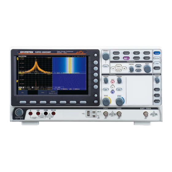
MPO-2000 series User Manual Appearance MPO-2104B/2204P 4-channel models Front Panel MPO-2102B/2202P 2-channel models Front Panel... - Page 17 GETTING STARTED LCD Display 8” WVGA TFT color LCD. 800 x 480 resolution, wide angle view display. Use the Menu Off key to hide the Menu Off Key onscreen menu system. The Option key is used to access Option Key installed options.
- Page 18 Function Keys different functions on the MPO-2000 series. Configures and runs automatic Measure measurements. Cursor Configures and runs cursor measurements. Configures and runs GW Instek applications. Configures the acquisition mode, Acquire including Segmented Memory acquisition. Display Configures the display settings.
- Page 19 GETTING STARTED Press the Autoset key to Autoset automatically set the trigger, horizontal scale and vertical scale. Press to Freeze (Stop) or continue Run/Stop Key (Run) signal acquisition (page 38). The run stop key is also used to run or stop Segmented Memory acquisition (page 84).
- Page 20 MPO-2000 series User Manual The Play/Pause key allows you to Play/Pause view each search event in succession – to effectively “play” through each search event. It is also used to play through a waveform/trace in zoom mode. Search The Search key accesses the search function menu to set the search type, source and threshold.
- Page 21 GETTING STARTED Sets the vertical scale of the (Vertical)SCALE Knob channel (TIME/DIV). Accepts external trigger signals External Trigger Input (page 156). Only on 2 channel models. Input impedance: 1MΩ Voltage input: ±15V (peak), EXT trigger capacitance: 16pF. Use the Math key to set and Math Key configure math functions.
- Page 22 MPO-2000 series User Manual The probe compensation output is Probe Compensation used for probe compensation. It Output also has an adjustable output frequency. By default this port outputs a 2Vpp, square wave signal at 1kHz for probe compensation. Please see page 198 for details. Used to turn the power on/off.
-
Page 23: Mpo-2000 Series Rear Panel
GETTING STARTED MPO-2000 series Rear Panel Outputs the signal for vertical scale Calibration Output accuracy calibration (page 369). The USB Device port is used for USB Device Port remote control. The LAN port is used for remote LAN (Ethernet) Port control over a network or when combined with the Remote Disk app, allows the scope to be... - Page 24 MPO-2000 series User Manual Outputs Go-No Go test results Go-No Go Output (page 270) as a 500us pulse signal. Output the GEN1 or GEN2 signal AWG Output from the Arbitrary Wave Generator function. (see page 203). Dual power supply outputs, , (see Power Supply outputs page 261).
-
Page 25: Display
GETTING STARTED Display Below is a general description of the main display. Analog Shows the analog input signal waveforms. Waveforms Channel 1: Yellow Channel 2: Blue Channel 3: Pink Channel 4: Green Shows serial bus data decoding. The values are Bus decoding displayed in hex or binary. - Page 26 MPO-2000 series User Manual Date and Time Current date and time (page 197). Trigger Level Shows the trigger level on the graticule. Memory Bar The ratio and the position of the displayed waveform compared to the internal memory (page 96). Triggered.
- Page 27 GETTING STARTED Channel 1, DC coupling, Channel Status 2V/Div. For channel details, see page 126.
-
Page 28: Set Up
MPO-2000 series User Manual Set Up Tilt Stand To tilt, pull the legs forward, as shown below. Tilt To stand the scope upright, push the legs back Stand under the casing as shown below. Power Up The MPO-2000 series accepts line voltages of 100 ~ Requirements 240V at 50 or 60Hz. -
Page 29: First Time Use
GETTING STARTED The MPO-2000 series recovers the state right before Note the power is turned OFF. The default settings can be recovered by pressing the Default key on the front panel. For details, see page 342. First Time Use This section describes how to connect, adjust the Background scale and compensate the probe. - Page 30 MPO-2000 series User Manual 6. Capture Signal Press the Autoset key. A square (Autoset) waveform appears on the center of the screen. For Autoset details, see page 36. 7. Select Vector Press the Display key, and set the Waveform display to Vector on the bottom menu.
-
Page 31: How To Use This Manual
GETTING STARTED 9. Start operations Continue with the other operations. Measurement: page 34 Configuration: page 73 Using the Spectrum Using the Power Analyzer: page 233. Supply: page 261. Using the DMM: page 252. Applications: page 233 Save/Recall: page 304 File Utilities: page 349 Hardcopy key: page 355 Remote Control: page Maintenance: page 364... - Page 32 MPO-2000 series User Manual Active parameters are highlighted for each menu item. For example in the example below, Coupling is currently set to DC. If a menu item can be toggled from one value or parameter to another, the available options will be visible, with the current option highlighted.
- Page 33 GETTING STARTED 5. If accessing a sub menu or setting a variable parameter, use the Variable knob to scroll through menu items or variables. Use the Select key to confirm and exit. The Select key is lit-up when such selection can be made. 6.
- Page 34 MPO-2000 series User Manual 9. Press the bottom menu key to toggle the parameter. Reduce Side Menu 10. To reduce the side menu, press the corresponding bottom menu that brought up the side menu. For example: Press the Source soft-key to reduce the Source menu.
- Page 35 GETTING STARTED Remove All Menus 12. Press the Menu Off key to reduce the side menu, press again to reduce the bottom menu. 13. The Menu Off key can also be Remove On- Screen Messages used to remove any on screen messages.
-
Page 36: Measurement
MEASUREMENT EASUREMENT Basic Measurement ........... 35 Channel Activation ................35 Autoset ....................36 Run/Stop ....................38 Horizontal Position/Scale ..............39 Vertical Position/Scale ................. 40 Automatic Measurement ..........42 Measurement Items ................42 Add Measurement ................. 46 Remove Measurement ................48 Measurement Shortcuts ................ -
Page 37: Basic Measurement
MEASUREMENT Basic Measurement This section describes the basic operations required in capturing, viewing and measuring the input signal. For more detailed or more specific operations, see the following chapters. Advanced Configuration → from page 73 Arbitrary Wave Generator → from page 201 ... -
Page 38: Autoset
MPO-2000 series User Manual To de-activate a channel, press De-activate Channel the corresponding channel key again. If the channel menu is not open, press the channel key twice (the first press shows the Channel menu). To activate the default state, Default Setup press Default (this will reset the system and recall the factory... - Page 39 MEASUREMENT Before After 3. To undo Autoset, press Undo Autoset from the bottom menu. Change modes 4. Choose between Fit Screen Mode and AC Priority Mode from the bottom menu. 5. Press the Autoset key again to use Autoset in the new mode. Fit Screen Mode AC Priority Autoset does not work in the following situations:...
-
Page 40: Run/Stop
MPO-2000 series User Manual Run/Stop By default, the waveform on the display is Background constantly updated (Run mode). Freezing the waveform by stopping signal acquisition (Stop mode) allows flexible observation and analysis. To enter Stop mode, two methods are available: pressing the Run/Stop key or using the Single Trigger mode. -
Page 41: Horizontal Position/Scale
MEASUREMENT Horizontal Position/Scale For more detailed configuration, see page 96. The horizontal position knob Set Horizontal Position moves the waveform left and right. Set Horizontal Pressing the horizontal position Position to 0 knob will reset the horizontal position to 0. Alternatively, pressing the Acquire key and then pressing Reset H Position to 0s from the bottom menu... -
Page 42: Vertical Position/Scale
MPO-2000 series User Manual Range 1ns/div ~ 100s/div, 1-2-5 increments The scale is displayed to the left of the H icon at the bottom of the screen. The display bar indicates how much Display bar of the waveform is displayed on the screen at any given time. - Page 43 MEASUREMENT The waveform can be moved Run/Stop mode vertically in both Run and Stop mode. To change the vertical scale, turn Select Vertical Scale the vertical SCALE knob; left (down) or right (up). 1mV/div ~ 10V/div Range 1-2-5 increments The vertical scale indicator for each channel on the bottom of the display changes accordingly.
-
Page 44: Automatic Measurement
MPO-2000 series User Manual Automatic Measurement The automatic measurement function measures and updates major items for Voltage/Current, Time, and Delay type measurements. Measurement Items V/I Measurements Time Meas. Delay Meas. Overview Difference between positive Voltage/Current Pk-Pk Measurement and negative peak. (peak to (=max −... - Page 45 MEASUREMENT Difference between the Amplitude global high value and the global low value, measured over the entire waveform or gated region. (=high − low) Global high voltage. See High page 51 for details. Global low voltage. See page 51 for details. Mean The arithmetic mean value is calculated for all data...
- Page 46 MPO-2000 series User Manual The Summation based on all Cycle Area data samples within the first cycle found in the gated region. Rise overshoot ROVShoot FOVShoot Fall overshoot Rise preshoot RPREShoot Fall preshoot FPREShoot Frequency of the waveform. Time Frequency Measurement Waveform cycle time.
- Page 47 MEASUREMENT Measures the number of -Pulses negative pulses. Measures the number of +Edges positive edges. Measures the number of -Edges negative edges. % Flicker Ratio in percentage of the peak-to-peak value to the sum of peak values. Ratio of the area above the Flicker Idx average to the total area during one cycle.
-
Page 48: Add Measurement
MPO-2000 series User Manual Time between: Source 1 first rising edge and Source 2 last falling edge. Time between: Source 1 first falling edge and Source 2 last rising edge. Time between: Source 1 first falling edge and Source 2 last falling edge. - Page 49 MEASUREMENT Pk-Pk, Max, Min, Amplitude, (Voltage/ High, Low, Mean, Cycle Mean, Current) RMS, Cycle RMS, Area, Cycle Area, ROVShoot, FOVShoot, RPREShoot, FPREShoot Frequency, Period, RiseTime, Time FallTime, +Width, –Width, Duty Cycle, +Pulses, -Pulses, +Edges, - Edges, %Flicker, FlickerIndex FRR, FRF, FFR, FFF, LRR, LRF, Delay LFR, LFF, Phase 4.
-
Page 50: Remove Measurement
MPO-2000 series User Manual Remove Measurement Individual measurements can be removed at any time using the Remove Measurement function. Remove 1. Press the Measure key. Measurement Item 2. Press Remove Measurement from the bottom menu. 3. Press Select Measurement and select the item that you want to remove from the measurement list. -
Page 51: Measurement Shortcuts
MEASUREMENT Measurement Shortcuts Users can use the Measure Shortcuts function to select the item to be measured, and then store the selected item in Shortcut 1~4, which can be selected to conduct measurements for the same product next time. Users just select the previously stored Shortcut 1~4 without making new selections from Add measurement and all the measurement items will be displayed on the screen to improve the measurement efficiency. - Page 52 MPO-2000 series User Manual Select transparent readout Transparent Readout background or turn off this function by press Transparent Readouts On/Off.
-
Page 53: Gated Mode
MEASUREMENT Gated mode Some automatic measurements can be limited to a “gated” area between cursors. Gating is useful for measuring a magnified waveform or when using a fast time base. The Gated mode has three possible configurations: Off (Full Record), Screen and Between Cursors. -
Page 54: High Low Function
MPO-2000 series User Manual 4. Press Source from the side menu and choose a measurement source. CH1~CH2 (or CH4 for 4CH Range models), Math 5. The results of Voltage and Time type measurements appear on the display. To remove the measurement results, Remove Measurements press OFF. - Page 55 MEASUREMENT Uses histograms to determine the Histogram high-low values. This mode ignores any pre-shoot or overshoot values. This mode is particularly useful for pulse-type waveforms Min-max Sets the high-low values as the minimum or maximum measured values. Set High-Low 1. Press the Measure key. 2.
-
Page 56: Statistics
MPO-2000 series User Manual Statistics The Statistics function can be used to view a Background number of statistics for the selected automatic measurements. The following information is displayed with the Statistics function: Value Currently measured value Mean The mean value is calculated from a number of automatic measurement results. -
Page 57: Reference Levels
MEASUREMENT 3. Select at least one automatic Page 46 measurement. 4. Press Statistics from the bottom menu. 5. Set the number of samples to be used in the mean and standard deviation calculations. 2~1000 Samples 6. Press Statistics and turn Statistics 7. - Page 58 MPO-2000 series User Manual 1. Press the Measure key. Panel Operation 2. Press Reference Levels from the bottom menu. 3. Set the reference levels from the side menu. Ensure the reference levels do not cross over. High Ref: Sets the high reference level.
-
Page 59: Cursor Measurement
MEASUREMENT Cursor Measurement Horizontal or vertical cursors are used to show the position and values of waveform measurements and math operation results. These results cover voltage, time, frequency and other math operations. When the cursors (horizontal, vertical or both) are activated, they will be shown on the main display unless turned off. - Page 60 MPO-2000 series User Manual 5. Use the Variable knob to move the movable cursor(s) left or right. The selected cursor(s) will move along the active Note waveform. To move along another waveform, select its corresponding channel and press the cursor key again to re-enter the cursor menu.
- Page 61 MEASUREMENT Example XY mode cursors measure a number of X by Y XY Mode measurements. See page 77. Cursor Time, rectangular, polar co- ordinates, product, ratio. Time, rectangular, polar co- Cursor ordinates, product, ratio. Delta (difference between cursors) Example...
-
Page 62: Use Vertical Cursors
MPO-2000 series User Manual Use Vertical Cursors 1. Press the Cursor key twice. Panel Operation/ Range 2. Press V Cursor from the bottom menu if it is not already selected. 3. When the V Cursor is selected, repeatedly pressing the V Cursor key or the Select key will toggle which vertical cursor is selected. - Page 63 MEASUREMENT Base (source wave units), % (ratio) Units Base or Ratio 7. To set the 0% and 100% ratio Reference references for the current cursor position, press Set Cursor Positions As 100%. Example FFT has different content. For FFT details, see page 65. Frequency/Time: cursor1, cursor2 dB/V: cursor1, cursor2 Delta (difference between cursors)
- Page 64 MPO-2000 series User Manual Cursor Rectangular, polar co-ordinates, product, ratio. Delta (difference between cursors) Example Cursor Mark The information of cursor is displayed on cursor (On/off) when the Cursor Mark function is activated.
-
Page 65: Math Operation
MEASUREMENT Math Operation Basic Math Overview & Operators Background The Math function performs basic math functions (addition, subtraction, multiplication, division) on the input signals or the reference waveforms. The resultant waveform will be shown on the screen in real-time. Addition (+) Adds the amplitude of two signals. - Page 66 MPO-2000 series User Manual 5. Select Source 2 from the side menu. Range CH1~4, Ref1~4 6. The math measurement result appears on the display. The vertical scale of the math waveform appears at the bottom of the screen. From left: Math function, source1, operator, source2, Unit/div Example Position and Unit To move the math waveform...
-
Page 67: Fft Overview & Window Functions
MEASUREMENT Multiplication VV, AA or W Division V/V, A/A Addition/Subtraction V or A To turn off the Math result from the Turn Off Math display, press the Math key again. FFT Overview & Window Functions Background The FFT function performs a Fast Fourier Transform on one of the input signals or the reference waveforms. -
Page 68: Fft Operation
MPO-2000 series User Manual For more complete measures and functions in the Note frequency domain of a signal, please also refer to the Spectrum Analyzer section of the MPO-2000 series on page 233. FFT Operation 1. Press the Math key. Panel Operation 2. - Page 69 MEASUREMENT Only FFT display is shown. FFT-only FFT-split The time domain waveform is shown in the upper section, whereas the FFT display is shown in the lower section. 4. Select the Source from the side menu. Range CH1~4, Ref 1~4 5.
- Page 70 MPO-2000 series User Manual Hanning, Hamming, Rectangular, Range and Blackman. 7. The FFT result represents the frequency- domain representation of a signal. Hence, the horizontal scale changes from time to frequency, and the vertical scale from voltage/current to dB/RMS. Math Source To move the FFT waveform Position and...
-
Page 71: Advanced Math Overview
MEASUREMENT To select the horizontal scale of the FFT waveform, press Horizontal repeatedly until the Hz/div parameter is highlighted and then use the VARIABLE knob. Advanced Math Overview The advanced math function allows complex Background math expressions to be created based on the input sources, reference waveforms or even the automatic measurements available from the Measure menu (see page 42). -
Page 72: Advanced Math Operation
MPO-2000 series User Manual Integers, floating point, or Figure floating point with exponent values. Adds automatic measurements to the expression. Measurement Not all automatic measurements are supported. Pk-Pk, Max, Min, Amp, High, Measurement Low, Mean, CycleMean, RMS, CycleRMS, Area, CycleArea, ROVShoot, FOVShoot, Freq, Period, Rise, Fall, PosWidth, NegWidth, Dutycycle, FRR, FRF,... - Page 73 MEASUREMENT 5. Press Clear to clear the expression entry area. 6. Use the Variable knob and the Select key to create an expression. Use the Variable knob to highlight a source, function, variable, operator, figure or measurement in orange. Press the Select key to make the selection.
- Page 74 MPO-2000 series User Manual 10. Press Mantissa. Use the Left and Right arrow keys to select a digit and use the variable knob to set the value of the selected digit. 11. Press Exponent. Use the Variable knob to set the exponent of the variable.
-
Page 75: Advanced Configuration
ADVANCED CONFIGURATION DVANCED CONFIGURATION Acquisition ..............76 Select Acquisition Mode ................ 76 Show Waveform in XY Mode ............. 77 Set the Record Length ................80 Segmented Memory Acquisition ........ 81 Segments Display ................... 82 Set the Number of Segments ............... 83 Run Segmented Memory ............... - Page 76 MPO-2000 series User Manual Save Button .................. 112 Edit Python APP Config Button ............112 Edit Button .................. 113 Restore Config Button ............... 113 User's Python Script Editing and Execution ........113 Dark Mode On/Off Button ............. 116 Built-in Python apps ..........118 Horizontal View ............
- Page 77 ADVANCED CONFIGURATION Setup Trigger Mode ................165 Using the Edge Trigger ............... 165 Using Advanced Delay Trigger ............167 Using Pulse Width Trigger ..............168 Using Video Trigger ................169 Pulse Runt trigger ................. 171 Using Rise and Fall Trigger ..............172 Using the Timeout Trigger ..............
-
Page 78: Acquisition
MPO-2000 series User Manual Acquisition The Acquisition process samples the analog input signals and converts them into digital format for internal processing. Select Acquisition Mode Background The acquisition mode determines how the samples are used to reconstruct a waveform. This is the default acquisition Sample mode. -
Page 79: Show Waveform In Xy Mode
ADVANCED CONFIGURATION 3. Select an acquisition mode from the side menu. 4. If Average was chosen, set the number of samples to be used for the average function. Mode Sample, Peak Detect, Average Average 2, 4, 8, 16, 32, 64, sample 128, 256, 512 Example... - Page 80 MPO-2000 series User Manual 1. Connect the signals to Connection Channel 1 (X-axis) and Channel 2 (Y-axis) or Channel 3 (X2-axis) and Channel 4 (Y2-axis). 2. Make sure a channel pair is active (CH1&CH2 or CH3&CH4). Press the Channel key if necessary. A channel is active if the channel key is lit.
- Page 81 ADVANCED CONFIGURATION To move the XY waveform position, use the vertical position knob: Channel 1 knob moves the XY waveform horizontally and Channel 2 knob moves the XY waveform vertically. Similarly, the X2 and Y2 axis can be positioned using the channel 3 and channel 4 vertical position knobs.
-
Page 82: Set The Record Length
MPO-2000 series User Manual Set the Record Length Background The number of samples that can be stored is set by the record length. Record length is important in an oscilloscope as it allows longer waveforms to be recorded. The maximum record length for the MPO-2000 SERIES depends on operating mode. -
Page 83: Segmented Memory Acquisition
ADVANCED CONFIGURATION Segmented Memory Acquisition The advanced segmented memory utility allows the scope memory to be divided into different segments. Each time the scope is triggered, it only acquires data for one segment of memory at a time. This allows you to optimize the scope memory to only perform signal acquisition during important signal events. -
Page 84: Segments Display
MPO-2000 series User Manual Segmented memory acquisition example: As shown above, the memory is divided into segments to increase the number of events that can be effectively captured with the same acquisition memory. Also notice that the scope doesn’t need to rearm the trigger between each segment, this makes the segmented memory function especially useful for high speed signals. -
Page 85: Set The Number Of Segments
ADVANCED CONFIGURATION Progress Indicator Indicates the number of segments that have to been captured relative to the set number of segments. Stop: The segments have finished Run/Stop Indicator acquiring or have been stopped. Run: The scope is ready to acquire segments. -
Page 86: Run Segmented Memory
MPO-2000 series User Manual Sets to 1 segment Set to Minimum The Select Segments icon is only available when Note Segments = OFF or when Segments is in the STOP mode (see the section below). Run Segmented Memory Before the Segmented Memory function can be Background used, set the trigger settings as appropriate for the signal you wish to use. -
Page 87: Navigate Segmented Memory
ADVANCED CONFIGURATION Alternatively, the Run/Stop key can be pressed. 5. The Stop Indicator will be shown when in the Stop mode. The scope is now ready to navigate or analyze the acquired segments. Rerun Segmented 6. To rerun the segments, press the Segments Stop Acquisition key to toggle the mode back to the Segments Run mode. -
Page 88: Play Through Each Segment
MPO-2000 series User Manual 2. To navigate to the segment of interest, press Current Seg from the side menu and use the Variable knob to scroll to the segment of interest. Alternatively, the Set to Minimum and Set to Maximum keys can be used to jump to the first and last segment respectively. -
Page 89: Measurement On Segments
ADVANCED CONFIGURATION Measurement on Segments The Segmented memory function can be used in Background conjunction with the automatic measurements configured in the Measurement menu (see page 42). Modes Segments This function will either perform Measure statistics calculations on the segments or tabulate a list of the measurement results for all the segments. - Page 90 MPO-2000 series User Manual Puts all the measurement Measurement List results for a segment in a list. All the currently selected automatic measurement results are listed. A maximum of 8 automatic measurements can be used with this function. To use automatic measurements with the segmented Note memory, automatic measurements must first be selected from the Measure menu before the...
- Page 91 ADVANCED CONFIGURATION 5. For statistic measurements, press Plot Source to choose which automatic measurement to use for the statistics calculations. The statistics for only one automatic measurement can be viewed at a time. 6. For the measurement list, press Source and select the source channel for measurement.
-
Page 92: Segment Info
MPO-2000 series User Manual Puts all the measurement results for a segment in Measurement List a list. Setup 9. Press Select and use the variable knob to scroll through each segment. Example: Measurement List Segment Info Operation 1. Press Analyze Segments from the bottom menu. -
Page 93: Display
ADVANCED CONFIGURATION Display The Display menu defines how the waveforms and parameters appear on the main LCD display. Display Waveform as Dots or Vectors Background When the waveform is displayed on the screen, it can be displayed as dots or vectors. Panel Operation 1. -
Page 94: Set The Intensity Level
MPO-2000 series User Manual Set the Intensity Level Background The intensity level of a signal can also be set to mimic the intensity of an analog oscilloscope by setting the digital intensity level. Panel Operation 1. Press the Display menu key. 2. - Page 95 ADVANCED CONFIGURATION 4. To set the graticule intensity, press Graticule Graticule Intensity Intensity from the side menu and edit the intensity value. 10~100% Range Example Graticule Intensity 100% Graticule Intensity 10% Backlight 5. To set the LCD backlight intensity, press Intensity Backlight Intensity from the side menu and edit the intensity value.
-
Page 96: Select Display Graticule
MPO-2000 series User Manual Select Display Graticule 1. Press the Display menu key. Panel Operation 2. Press Graticule from the bottom menu. 3. From the side menu choose the graticule display type. Full : Shows the full grid; X and Y axis for each division. -
Page 97: Freeze The Waveform (Run/Stop)
ADVANCED CONFIGURATION Transparent readout function is turned OFF Freeze the Waveform (Run/Stop) For more details about Run/Stop mode, see page 38. Panel Operation 1. Press the Run/Stop key. The Run/Stop key turns red and waveform acquisition is paused. 2. The waveform and the trigger freezes. -
Page 98: Turn Off Menu
MPO-2000 series User Manual Turn Off Menu 1. Press the Menu Off key Panel Operation below the side menu keys to reduce a menu. The menu key needs to be pressed each time to reduce one menu. See page 29 for more information. -
Page 99: Python Script Execution
ADVANCED CONFIGURATION Python script execution Introduction The innovative feature of running Python scripts is built into the MPO-2000 series to help users understand what Python scripts can do in the system and how they can help users save measurement time and improve work efficiency. MPO-2000 series provides a pre- installed Python APP with source code and circuit diagrams for testing. -
Page 100: Difference Between Basic And Professional Version
MPO-2000 series User Manual Difference between Basic and Professional version The MPO-2000 series is categorized into two versions based on their functional specifications: Basic and Professional. Aside from the variation in bandwidth, models with the "B" suffix indicate the Basic version, offering fewer system resources for Python script execution. - Page 101 ADVANCED CONFIGURATION Features 1. Available Memory for Python Scripts In the Basic version of the MPO-2000 series, Python scripts have access to a smaller amount of internal memory, suitable for smaller-scale control software. For applications that require waveform data acquisition and processing, it is recommended to set the sampling point count to a maximum of 1,000, as exceeding this limit may lead to insufficient memory.
- Page 102 MPO-2000 series User Manual Currently, the MPO-2000 supports USB CDC- ACM devices primarily from our company's PSW series, PFR series, and PPX series of power supply equipment. If users have control requirements for other products from our company, please consult with us beforehand. Other non-company devices with USB interfaces are not supported, as their driver mechanisms may differ from our company's...
- Page 103 ADVANCED CONFIGURATION 4. Packaging Python Scripts as Python Apps Moreover, the Professional version also features the capability to package Python scripts as Python App installation files (.xpy). Advanced users can bundle their designed Python script-related files and provide them for installation on specific MPO-2000 series. During the packaging process, users must prepare a list of MAC addresses and serial numbers for the target MPO-2000 series in...
-
Page 104: Python App Operation
MPO-2000 series User Manual Python APP Operation Front panel for MPO-2000 series As shown in the diagram below, the MPO-2000 provides a variety of measurement methods, including the BJT I-V Characteristics Auto Measurement App, LED Characteristics Curve Measurement App, LC Oscillator Circuit Temperature and Frequency Characteristics Curve Auto Measurement App, Fuse Tolerance Test App, and an example App for recording measurement data of multiple components by using a USB barcode scanner. -
Page 105: Menu Description
ADVANCED CONFIGURATION Menu Description Install/ Uninstall Button This is the install/uninstall menu for third-party Python Apps. By selecting the “Install/Uninstall” option at the bottom left of the LCD screen, users can perform procedures such as installation, uninstallation, saving settings, and packaging (Make Package). - Page 106 MPO-2000 series User Manual 1. Press the Install button to access Installation the internal flash disk or USB process drive menu. 2. Select the Python App installation file (*.xpy). 3. Press the Select key on the front panel to initiate the installation procedure.
-
Page 107: Uninstall Button
ADVANCED CONFIGURATION Uninstall Button 1. Access the menu, select the Python App you Uninstallation wish to uninstall, and proceed with the process uninstallation process. Users cannot remove built-in Python Apps; users can Note only uninstall the third party Python Apps. 2. -
Page 108: Make Package Button
MPO-2000 series User Manual Make Package Button The packaging process allows users to bundle their authored Python scripts and other related files into a Python App installation file (.xpy). Before initiating the packaging process, several essential files need to be prepared, the purpose of these files are described below. - Page 109 ADVANCED CONFIGURATION “test_led_pro.txt.” When running the script in the future, it will automatically load the parameters from “test_led_pro.txt.” Menu icon with the file extension .bmp. test_led_pro.bmp Preview images in the message box at the test_led_pro.png bottom of the Python App menu screen, with the file extension .png.
- Page 110 MPO-2000 series User Manual 1. “Folder_Name” Defines the top-level folder name. In the root directory of the internal disk or USB flash drive, a folder will be created based on the string specified on the right side of the equal sign in “Folder_Name.”...
-
Page 111: Make Package Operation
ADVANCED CONFIGURATION Make Package Operation 1. Press the Make Package button. Make Package process 2. Selecting the destination folder, and then press the Select Package Folder key. The MPO-2000 system will check if the folder name matches the script name and whether there is an “xpy_setup.txt”... -
Page 112: Simplified Packaging
MPO-2000 series User Manual If the packaging folder is on the USB flash drive, the resulting installation file will be placed on the USB flash drive. If the folder is on the internal flash disk, the resulting installation file will be on the internal flash disk. Simplified Packaging If the script folder contains only “*.py”... -
Page 113: Copy Python App Button
ADVANCED CONFIGURATION Copy Python APP Button Users can choose to copy the script source “*.py” and parameter settings file “*.txt” to the internal flash disk or the USB flash drive by pressing the “Copy Python APP” button in the lower left corner of the screen. -
Page 114: Disk/ Usb App Button
MPO-2000 series User Manual Disk/ USB APP Button This function allows users to save the specific Python app source code to the internal flash disk or USB flash drive. Save Button Pressing this button will save the source code (*.py) and parameter settings file (*.txt) to the internal flash disk or a USB flash drive. -
Page 115: Edit Button
ADVANCED CONFIGURATION Edit Button Access the current Python APP’s parameter configuration file editing screen. Please insert a USB keyboard into the MPO-2000 to modify the parameter settings. After making changes, press Ctrl+S to save the data or press ESC to exit the editing screen. - Page 116 MPO-2000 series User Manual 1. Press Edit button. Steps 2. Select the Python script (*.py) or parameter configuration file (*.txt) which want to edit. 3. Rotate the VARIABLE knob on the front panel and press the Select key to select the file (The following example is “presentation.py”)
- Page 117 ADVANCED CONFIGURATION 4. Once in the editing screen, use the USB keyboard to modify to the content. Press Ctrl+S on the keyboard to save the file, or press the Esc key to exit the editing screen after editing completed. 1. Press the Run button. Execute the specific Python program...
-
Page 118: Dark Mode On/Off Button
MPO-2000 series User Manual During execution, the upper left corner of the LCD screen will display a red “μPy” indicating that the MPO-2000 is running the Python program currently. Dark Mode On/Off Button This botton is used to enable or disable the dark mode for the editing screen... - Page 119 ADVANCED CONFIGURATION...
-
Page 120: Built-In Python Apps
MPO-2000 series User Manual Built-in Python apps The built-in Python APP applications in MPO-2000 series are as follows. BJT Characteristic Curves. LC Oscillating Circuit Frequency and Temperature Characteristics Curves. Fuse Endurance Test. LED Characteristics Curves. WebIDE - Web-based Python Debugging Tool. ... -
Page 121: Horizontal View
ADVANCED CONFIGURATION Horizontal View This section describes how to set the horizontal scale, position, and waveform display mode. Move Waveform Position Horizontally Panel Operation The horizontal position knob moves the waveform left/right. As the waveform moves, a position indicator on the top of the display indicates the horizontal position of the waveform in memory. -
Page 122: Select Waveform Update Mode
MPO-2000 series User Manual In Run mode, the memory bar and waveform size Run Mode keep their proportion. When the timebase becomes slower, roll mode is activated (if the trigger is set to Auto). Stop Mode In Stop mode, the waveform size changes according to the scale. - Page 123 ADVANCED CONFIGURATION Select Update 1. Press the Trigger Menu key. Mode Manually 2. Press Mode Auto/Normal key from the bottom menu to let the equipment choose between Auto (Untriggered Roll) and Normal mode. The auto (Untriggered Roll) trigger mode enables free-running and roll mode (timebase >=100ms/div) acquisitions.
-
Page 124: Zoom Waveform Horizontally
MPO-2000 series User Manual Zoom Waveform Horizontally When in Zoom mode, the screen is split into 2 Background sections. The top of the display shows the full record length, while the bottom of the screen shows the normal view. Panel Operation 1. -
Page 125: Play/Pause
ADVANCED CONFIGURATION To increase the zoom range, use the Zoom horizontal Scale knob. The zoom time base at the bottom of the screen will change accordingly. Use the Horizontal Position knob to Move the Zoom Window pan the zoom window horizontally. To reset the zoom position, press the Horizontal Position knob. - Page 126 MPO-2000 series User Manual 1. Press the Play/Pause menu key. Panel Operation 2. The scope will go into the Zoom Play mode and begin to scroll through the acquisition (from left to right). The full-record length waveform will be shown at the top and the zoomed section will be shown at the bottom.
- Page 127 ADVANCED CONFIGURATION Alternatively, use the horizontal position knob to control the scroll speed. Turning the Horizontal knob determines the speed and direction of the scrolling. Reset the Zoom To reset both the zoom position and Position horizontal position, press Reset Zoom &...
-
Page 128: Vertical View (Channel)
MPO-2000 series User Manual Vertical View (Channel) This section describes how to set the vertical scale, position, and coupling mode. Move Waveform Position Vertically Panel Operation 1. To move the waveform up or down, turn the vertical position knob for each channel. 2. -
Page 129: Select Vertical Scale
ADVANCED CONFIGURATION Select Vertical Scale Panel Operation To change the vertical scale, turn the vertical SCALE knob; left (down) or right (up). The vertical scale indicator on the bottom left of the display changes accordingly for the specific channel. 1mV/div ~ 10V/div. 1-2-5 Range increments In Stop mode, the vertical scale setting can be... -
Page 130: Invert Waveform Vertically
MPO-2000 series User Manual Example Observing the AC portion of the waveform using AC coupling DC coupling AC coupling Invert Waveform Vertically 1. Press the Channel key. Panel Operation 2. Press Invert to toggle Invert On or Off. -
Page 131: Limit Bandwidth
ADVANCED CONFIGURATION Limit Bandwidth Bandwidth limitation puts the input signal into a Background selected bandwidth filter. This function is useful for cutting out high frequency noise to see a clear waveform shape. The bandwidth filters available are dependent on the bandwidth of the oscilloscope model. Also refer to the digital filter application, page 279. - Page 132 MPO-2000 series User Manual 2. Press More key from the bottom menu 3. Rotate the VARIABLE knob to input a desired value of vertical position.
-
Page 133: Expand By Ground/Center
ADVANCED CONFIGURATION Expand by Ground/Center When the voltage scale is changed, the Expand Background function designates whether the signal expands from the center of the screen or from the signal ground level. Expand by center can be used to easily see if a signal has a voltage bias. Expand by ground is the default setting. -
Page 134: Select Probe Type
MPO-2000 series User Manual Expand by Center Select Probe Type Background A signal probe can be set to voltage or current. Panel Operation 1. Press the Channel key. 2. Press More key from the bottom menu 3. Press Probe from the side menu. 4. -
Page 135: Select Probe Attenuation Level
ADVANCED CONFIGURATION Select Probe Attenuation Level An oscilloscope probe has an attenuation switch Background to lower the original DUT signal level to the oscilloscope input range, if necessary. The probe attenuation selection adjusts the vertical scale so that the voltage level on the display reflects the real value on a DUT. -
Page 136: Set The Deskew
MPO-2000 series User Manual Set the Deskew The deskew function is used to compensate for the Background propagation delay between the oscilloscope and the probe. 1. Press one of the Channel keys. Panel Operation 2. Press More key from the bottom menu 3. -
Page 137: Bus Key Configuration
ADVANCED CONFIGURATION Bus Key Configuration The Bus key is used to configure the Serial bus inputs and parallel bus inputs. The bus inputs can be either analog or digital. The Bus menu also features event tables to track and save your bus data. The Bus key is used in conjunction with the Bus trigger (page 176) to decode serial or parallel bus signals. -
Page 138: Serial Bus Overview
MPO-2000 series User Manual CAN: Purple = Error frame, Data length control (DLC), Overload. Yellow = Identifier. Cyan = Data. Orange = CRC. Red = Bit stuffing error Parallel All read words are shown in purple (no clock) or white (a clock is defined among the channels). - Page 139 ADVANCED CONFIGURATION UART Universal Asynchronous Receiver Transmitter. The UART bus is able to accommodate a wide range of various common UART serial communications. The UART serial bus software is suitable for a number of RS-232 protocol variants. Inputs Tx, Rx Tx, Rx Threshold Configuration Baud rate, Parity, Packets, End of...
- Page 140 MPO-2000 series User Manual The CAN (Controller Area Network) bus is a 2- wire, message-based protocol. Inputs CAN Input Threshold CAN Input Configuration Signal Type, Bit Rate Start of Frame, Type of Frame, Trigger On Identifier, Data, Id & Data, End of Frame, Missing Ack, Bit Stuffing Err.
-
Page 141: Uart Serial Bus Configuration
ADVANCED CONFIGURATION UART Serial Bus Configuration The UART bus menu is designed to decode RS-232 and other common RS-232 variants such as RS-422, RS-485. The software configuration is also flexible enough to decode the many proprietary protocols based on RS-232. Basic RS-232 protocol uses single-ended data Background transmissions. -
Page 142: I 2 C Serial Bus Interface
MPO-2000 series User Manual 4. Press Define Inputs from the Define Inputs bottom menu. 5. From the side menu choose the Tx Input and the Rx Input source and the signal polarity. OFF, CH1~CH4 or OFF OFF, CH1~CH4 or OFF Polarity Normal (High = 0), Inverted (High = Configuration The Configure key sets the baud rate, number of data... - Page 143 ADVANCED CONFIGURATION addressing and multiple masters. The scope will trigger on any of the following conditions: a start/stop condition, a restart, a missing acknowledge message, Address, Data or Address & Data frames. The I C trigger can be configured for 7 or 10 bit addressing with the option to ignore the R/W bit as well as triggering on a data value or a specific address and direction (read or write or both).
-
Page 144: Spi Serial Bus Interface
MPO-2000 series User Manual SPI Serial Bus Interface The serial peripheral interface (SPI) is a full duplex 4 wire synchronous serial interface. The 4 signals lines: Serial clock line (SCLK), slave select (SS), Master output/slave input (MOSI, or SIMO) and the Master input/slave output (MISO, or SOMI). The word size is configurable from 4 to 32 bits. - Page 145 ADVANCED CONFIGURATION 7. Press Select from the side menu. Choose SCLK, SS, MOSI or MISO line thresholds. SCLK, SS, MOSI, MISO Range 8. Press Threshold from the side menu and configure the threshold. 9. Press the Choose Preset to select the following settings TTL, 5.0V CMOS, 3.3 CMOS, 2.5V COMS,...
- Page 146 MPO-2000 series User Manual 13. Press Event Table from the side menu to toggle the event table On or Off. Event On, Off 14. To save the event table, press Save Event Table.
-
Page 147: Can Serial Bus Interface
ADVANCED CONFIGURATION CAN Serial Bus Interface The controller area network (CAN) bus is a half duplex 2 wire synchronous serial interface. The CAN bus is a multi-master communication system that relies on arbitration to solve contention issues. The MPO-2000 series supports both CAN 2.0A and 2.0B. The CAN bus uses two wires, CAN-High and CAN-Low. -
Page 148: Lin Serial Bus Interface
MPO-2000 series User Manual 6. Press Bit Rate from the bottom menu and set the bit rate. Custom, 10kbps, 20kbps, 50kbps, Bit Rate 125kbps, 250kbps, 500kbps, 800kbps, 1Mbps LIN Serial Bus Interface The local interconnect network (LIN) bus is a single wire interface. Panel operation 1. -
Page 149: Bus Encoding
ADVANCED CONFIGURATION 6. Press Configure from the bottom menu. 7. From the side menu select configuration items. Custom, 1.2kbps, 2.4kbps, Bit Rate 4.8kbps, 9.6kbps, 10.417kbps, 19.2kbps V1.x, V2.x, Both LIN Standard Include Parity On, Off Bits with Id Bus Encoding The bus that is displayed on the screen or in the Background event tables can be set to either hex or binary... - Page 150 MPO-2000 series User Manual LIN Input 3. Press Choose Preset to select a pre- set logic threshold. Logic Type Threshold 1.4V 2.5V 5.0V CMOS 1.65V 3.3V CMOS 1.25V 2.5V CMOS -1.3V PECL 3.7V 4. Press Threshold to set a user defined threshold for the currently selected input.
-
Page 151: Serial Bus Event Tables
ADVANCED CONFIGURATION Serial Bus Event Tables The serial bus event tables list when each data Background event on the bus occurred. The data is displayed as either hex or binary, depending on the bus display settings. Event tables can be saved to disk in a CSV format. The files will be named “Event_TableXXXX.CSV”, where XXXX is a number from 0000 to 9999. - Page 152 MPO-2000 series User Manual Example: UART Event table Example: C Event table Example: C Data Detail Data Detail is only available with the I C bus. Note...
-
Page 153: Event Tables Format
ADVANCED CONFIGURATION Example: CAN Event table Example: LIN Event table Event Tables Format Each bus type (UART, I C, SPI, CAN and LIN) can have an event table saved containing each bus event as a .CSV file. An event is defined as a packet/frame/word or associated set of data being successfully read according to the specific operating conditions of each bus (Start of frame, acknowledgements, checksums, etc …). -
Page 154: Adding A Label To A Bus
MPO-2000 series User Manual Event Table Data Each event table saves a timestamp of each event relative to the trigger as well as the data in each frame/packet at the time of an event. The frame/packet data is saved in HEX format. The table below lists in order the data saved for each event table. - Page 155 ADVANCED CONFIGURATION ACK, AD0, ADDR, ANALOG, Labels BIT, CAS, CLK, CLOCK, CLR, COUNT, DATA, DTACK, ENABLE, HALT, INT, IN, IRQ, LATCH, LOAD, NMI 3. Press Edit Character to edit the Edit Label current label. 4. The Edit Label window appears. 5.
-
Page 156: Using Cursors With The Serial Bus Or Parallel Bus
MPO-2000 series User Manual This key must be pressed to save the label, even for Note the preset labels. Press Cancel to cancel the editing and return to the Edit Label menu. 6. The label will appear next to the bus indicator. Below, the label “ACK”... - Page 157 ADVANCED CONFIGURATION 4. The cursor position information appears on the top left hand side of the screen. Example: I C cursors. Hor. position, Bus value(s) Cursor Hor. position, Bus value(s) Cursor 5. When cursor mark is selected ”ON” The cursor will mark readout directly on waveform.
-
Page 158: Trigger
MPO-2000 series User Manual Trigger The trigger configures the conditions for when the MPO-2000 SERIES captures a waveform. Trigger Type Overview Edge The edge trigger is the simplest trigger type. An edge trigger triggers when the signal crosses an amplitude threshold with either a positive or negative slope. - Page 159 ADVANCED CONFIGURATION Delay trigger example (by time) Edge trigger Delay Source Delay time length First triggering point Pulse Width Triggers when the pulse width of the signal is less than, equal, not equal or greater than a specified pulse width. Pulse width Extracts a sync pulse from a video format signal, Video...
-
Page 160: Trigger: Types And Sources
MPO-2000 series User Manual Trigger level threshold Timer Triggering point Triggers on SPI, UART, I2C, CAN or LIN bus events. Trigger: types and sources Sources versus Trigger sources types Analog Trigger types CH1 ~ CH4 EXT* AC Line Edge √ √... - Page 161 ADVANCED CONFIGURATION AC mains signal AC Line Except for: Video, Pulse Runt, Rise & Fall, Bus and Logic Alternate between channel sources for Alternate the trigger source. EXT Probe For EXT trigger source only. Set the probe as either current or voltage. Attenuation For EXT trigger source only.
- Page 162 MPO-2000 series User Manual When pressing the Single Single key, the MPO-2000 SERIES acquires a waveform only once when a trigger event occurs, and then stops acquiring (the oscilloscope falls into Stop mode). Press the Single key to acquire a waveform again.
- Page 163 ADVANCED CONFIGURATION Sets the holdoff time. Holdoff Holdoff Set to Set the holdoff time to the minimum. Minimum Delay (Delay) Time Sets the delay time (4ns ~ 10s) between the trigger event and the real trigger timing. Sets the number of events (1 ~ 65535) Event passed after the trigger event, until the real trigger timing.
- Page 164 MPO-2000 series User Manual 1.4V 2.5V 5.0V CMOS 1.65V 3.3V CMOS 1.25V 2.5V CMOS -1.3V PECL 3.7V National Television System Committee Standard NTSC (Video) Phase Alternate by Line SECAM SEquential Couleur A Memoire Positive polarity (triggered on the high Polarity to low transition) (Pulse Width, Video)
- Page 165 ADVANCED CONFIGURATION Selects the conditions for the serial bus triggers. Trigger On (Bus) Tx Start Bit, Rx Start Bit, Tx End of UART Bus Packet, Rx End of Packet, Tx Data, Rx Data, Tx Parity Error, Rx Parity Error Start, Repeat Start, Stop, Missing Ack, Address, Data, Address/Data SS Active, MOSI, MISO, MOSI&MISO Start of Frame, Type of Frame,...
-
Page 166: Setup Holdoff Level
MPO-2000 series User Manual Setup Holdoff Level The holdoff function defines the waiting period Background before the MPO-2000 starts triggering again after a trigger point. The holdoff function ensures a stable display if there are a number of points in a periodic waveform that can be triggered. -
Page 167: Setup Trigger Mode
ADVANCED CONFIGURATION Setup Trigger Mode The trigger mode can be set to Normal or Auto Background (untriggered roll). The triggering mode applies to all the trigger types. Panel Operation 1. Press the Trigger menu key. 2. Press Mode from the bottom menu to change the triggering mode. - Page 168 MPO-2000 series User Manual Channel 1 ~ 4 (Alternate On/Off), Range EXT (Ext Probe: Volt/Current, Attenuation: 1mX~1kX, CH2 models only), AC Line and D0~D15. 6. Press Coupling from the bottom bezel menu to select the trigger coupling or frequency filter settings.
-
Page 169: Using Advanced Delay Trigger
ADVANCED CONFIGURATION Using Advanced Delay Trigger Panel Operation 1. Set the edge trigger source. This Page 165 will set the initializing trigger for the delay source. 2. Press the trigger Menu key. 3. Press Type from the lower bezel menu. 4. -
Page 170: Using Pulse Width Trigger
MPO-2000 series User Manual 8. To Delay by Time (Duration), press Time from the side menu and set the delay time. Range 4ns ~ 10s (by time) Set to minimum 9. To Delay by Event, press Event from the side menu and set the number of events. -
Page 171: Using Video Trigger
ADVANCED CONFIGURATION 6. Press Polarity to toggle the polarity type. Positive (high to low transition) Range Negative (low to high transition) 7. Press When from the lower bezel. Then use the side menu to select the pulse width condition and width. >... - Page 172 MPO-2000 series User Manual From left: source, video standard, field, line, coupling 4. Press Source from the lower bezel. 5. Use the side menu to select the video trigger source. Channel 1 ~ 4 Range 6. Press Standard on the bottom bezel.
-
Page 173: Pulse Runt Trigger
ADVANCED CONFIGURATION Pulse Runt trigger Panel Operation 1. Press the trigger Menu key. 2. Press the Type key from the lower bezel menu. 3. Select Others → Pulse Runt from the side menu. The Pulse and Runt indicator appears at the bottom of the display. -
Page 174: Using Rise And Fall Trigger
MPO-2000 series User Manual 8. Use the side menu to set the upper threshold. Range The adjustable range is restricted to eight vertical divisions on the LCD screen. 9. Use the side menu to set the lower threshold. The adjustable range is restricted to Range eight vertical divisions on the LCD screen. - Page 175 ADVANCED CONFIGURATION Rising edge, falling edge, either Range 6. Press When from the lower menu. Then use the side menu to select the logic conditions and true or false status. Condition > , < , = , ≠ 4ns ~ 10s Width 7.
-
Page 176: Using The Timeout Trigger
MPO-2000 series User Manual Using the Timeout Trigger 1. Press the trigger Menu key. Panel Operation 2. Press the Type key from the lower bezel menu. 3. Select Others Timeout from the side menu. The Timeout indicator appears at the bottom of the display. - Page 177 ADVANCED CONFIGURATION Then use the side menu to select trigger conditions. Condition Stays High, Stays Low, Either 8. Press Level from the lower bezel to set the trigger level. 9. Set the level using the side menu. Analog 00.0V~ 5 screen divisions channel Set to TTL 1.4V Range...
-
Page 178: Using The Bus Trigger
MPO-2000 series User Manual Using the Bus Trigger The Bus trigger is used to trigger the oscilloscope on UART, I2C, SPI, CAN or LIN serial bus signals. UART BUS Trigger Settings The UART bus trigger conditions can be set at any time after the bus settings have been set to UART. - Page 179 ADVANCED CONFIGURATION 6. Press Data from the bottom menu. 7. Press Number of Bytes from the side menu and choose the number of bytes for the data. UART 1~10 Bytes 8. Press Data from the side menu to edit the triggering data. To edit the data, use the Variable knob to highlight a binary or hex digit and press Select.
-
Page 180: C Bus Trigger Settings
MPO-2000 series User Manual C Bus Trigger Settings The I C bus trigger conditions can be set at any time after the bus settings has been set to I Panel Operation 1. Set the Bus to I C in the bus menu. Page 140 2. - Page 181 ADVANCED CONFIGURATION 8. Press Addressing Mode to toggle between 7 and 10 bit addressing modes. 9. Press Data from the side menu to edit the triggering data. To edit the data, use the Variable knob to highlight a binary or hex digit and press Select.
- Page 182 MPO-2000 series User Manual Press Apply Preset to set the default address to the preset. Presets are not available for Trigger On Address/Data. Note 13. Press Address from the side menu to manually edit the triggering address. To edit the address, use the Variable knob to highlight a binary or hex digit and press Select.
-
Page 183: Spi Bus Trigger Settings
ADVANCED CONFIGURATION SPI Bus Trigger Settings The SPI bus trigger conditions can be set at any time after the bus setting has been set to SPI. Panel Operation 1. Set the Bus to SPI in the bus Page 142 menu. 2. -
Page 184: Can Bus Trigger
MPO-2000 series User Manual 8. Press MOSI or MISO from the side menu to edit the triggering data. To edit the data, use the Variable knob to highlight a binary or hex digit and press Select. Use the Variable knob to choose a value for the digit and press Select to confirm. - Page 185 ADVANCED CONFIGURATION Trigger On Start of Frame, Type of Frame, Identifier, Data, Id & Data, End of Frame, Missing Ack, Bit Stuffing 6. If Type of Frame was configured for the Trigger Trigger On –Type of Frame On setting, then the type of frame can be configured from the side menu.
-
Page 186: Lin Bus Trigger
MPO-2000 series User Manual 11. Press Number of Bytes from the side menu and choose the number of bytes for the data. Bytes 1~8 Bytes 12. Press Data from the side menu to edit the triggering data. To edit the data, use the Variable knob to highlight a binary or hex digit and press Select. - Page 187 ADVANCED CONFIGURATION 4. Select Others → Bus from the side menu. The Bus indicator appears at the bottom of the display. From left: Bus trigger, Trigger source 5. Press Trigger On and select the triggering condition for the selected bus. Trigger On Sync, Identifier, Data, Id and Data, Wakeup Frame, Sleep Frame, Error.
- Page 188 MPO-2000 series User Manual 9. Press Number of Bytes from the side menu and choose the number of bytes for the data. Bytes 1~8 Bytes 10. Press Data from the side menu to edit the triggering data. To edit the data, use the Variable knob to highlight a binary or hex digit and press Select.
-
Page 189: Search
ADVANCED CONFIGURATION Search The search feature can be used to search for events on the analog and digital input channels. The events that can be searched for are similar to the events that are used for the trigger system. The only difference is that the search feature uses the measurement threshold levels rather than the trigger level to determine events. - Page 190 MPO-2000 series User Manual 2. Press Search from the bottom menu and turn the Search function on. 3. Press Search Type from the bottom menu and select the type of search. The search events are configured in the same fashion as the trigger events.
-
Page 191: Copying Search Event To/From Trigger Events
ADVANCED CONFIGURATION Copying Search Event To/From Trigger Events As the trigger system and search feature have Background similar settings, their settings can be used interchangeably by using the Copy functions. Interchangeable Edge, Pulse Width, Pulse Runt, Rise and Fall Times, Settings Logic and Bus (FFT Peak has no trigger equivalent) Panel Operation 1. -
Page 192: Save Search Marks
MPO-2000 series User Manual 3. Use the search arrow keys to move between each search event. Search events can be navigated in both stop and run mode. When using the arrow keys to navigate to each event, the “current event” will always be centered on the display. -
Page 193: Setting/Clearing Single Search Events
ADVANCED CONFIGURATION Setting/Clearing Single Search Events In addition to searching for search events based Background on Search Type settings, custom search marks can be created with the Set/Clear key. Set Search Event 1. Navigate to a point of interest using the horizontal position knob or some other method. -
Page 194: Fft Peak
MPO-2000 series User Manual FFT Peak The FFT Peak search type can be used to mark all Background FFT peaks that are above a certain threshold. The search function can support up to 10,000 events, Note however only 1,000 events can be displayed on screen at once. - Page 195 ADVANCED CONFIGURATION 6. Next, select the event search method by pressing Method from the bottom menu. Select Max Peak to search by a selected number of “max” peaks. Select Level to set the threshold level for the search events. Any peaks above the threshold level will be seen as a search event.
- Page 196 MPO-2000 series User Manual The event table will appear on the screen. Save Event Table 8. To save the event table, insert a USB memory drive into the front panel USB-A port. 9. Press Save Event Table. The event table will be saved as PeakEventTbXXXX.csv.
-
Page 197: System Settings And Miscellaneous Settings
ADVANCED CONFIGURATION System Settings and Miscellaneous Settings This section describes how to set the interface, language, time/date, probe compensation signal, erase the internal memory and access useful QR codes. Select Menu Language The MPO-2000 SERIES has a number of different Description languages to choose from. -
Page 198: Erase Memory
MPO-2000 series User Manual Erase Memory Background The Erase Memory function will erase all internal waveforms, setup files and labels from internal memory. Waveform 1~20, Setting memory 1~20, Reference Erased Items 1~4, Labels Panel Operation 1. Press the Utility key. 2. -
Page 199: Erase Disk
ADVANCED CONFIGURATION Erase Disk The Erase Disk function will erase all files form Background the internal flash driver. Waveform 1~20, Setting memory 1~20, Reference Erased Items 1~4, Labels Panel Operation 1. Press the Utility key. 2. Press System from the lower menu. -
Page 200: Set Date And Time
MPO-2000 series User Manual Set Date and Time 1. Press the Utility key. Panel Operation/ Parameter 2. Press Date & Time on the lower menu. 3. Set the Year, Month, Day, Hour and Minute from the side menu. 2000 ~ 2037 Year 1 ~ 12 Month... -
Page 201: Qr Code Reader Function
The QR Code reader function displays a number Background of preset QR codes that link to useful websites. QR Code Items GW Instek website GW Instek contact window (marketing department) Panel Operation/ 1. Press the Utility key. Parameter 2. - Page 202 MPO-2000 series User Manual 5. Use a QR code reader app on your smart phone or tablet to read one of the QR codes.
-
Page 203: Arbitrary Wave Generator
ARBITRARY WAVE GENERATOR RBITRARY WAVE GENERATOR Arbitrary Wave Generator Operation ......202 Overview ....................202 Rear Panel ....................202 AWG Display Overview ..............203 Generator Connection ................. 203 Output Setup ..................204 Select the Active Channel ............204 Turn the Output On for the Selected Channel ..... 205 Setting the Load Impedance ............. -
Page 204: Arbitrary Wave Generator Operation
MPO-2000 series User Manual Arbitrary Wave Generator Operation Overview The AWG is a full-function dual channel arbitrary Background waveform generator. Waveforms Arbitrary, Sine, Square, Pulse, Ramp, DC, Noise, Sinc, Gaussian, Lorentz, Exp. Rise, Exp. Fall, Haversine, Cardiac AM, FM, FSK, Sweep Functions Rear Panel Outputs for the Generator 1 or... -
Page 205: Awg Display Overview
ARBITRARY WAVE GENERATOR AWG Display Overview State Display The state display is used to visually show the major channel settings when you are in the AWG menu. The AWG channel status indicators show the AWG Generator Status Indicators active channels, output waveforms and function. AWG status Channel status indicator... -
Page 206: Output Setup
MPO-2000 series User Manual 1. Connect the BNC output (GEN1 or GEN2) to Connection the DUT using the GTL-101 BNC-Alligator clip cables. Output Setup The Output Setup menu allows you to select a channel, to turn the output on or off for the selected channel, configure the load impedance and the phase of the output. -
Page 207: Turn The Output On For The Selected Channel
ARBITRARY WAVE GENERATOR Turn the Output On for the Selected Channel The output for each generator channel can be Background turned on or off independently. Panel Operation 1. Press Output to toggle the selected channel on or off. Setting the Load Impedance The load impedance can be independently set for Background each generator channel. -
Page 208: Gen1 And Gen2 Setup
MPO-2000 series User Manual GEN1 and GEN2 Setup The GEN1 Setup and GEN2 Setup selects the output waveform, waveform settings (amplitude, frequency, offset), modulation mode or allows you to create arbitrary waveforms. Selecting a Waveform The AWG option has 14 selectable waveforms, Background including a user-created arbitrary waveform. -
Page 209: Waveform Settings
ARBITRARY WAVE GENERATOR Waveform Settings The Waveform Settings sub menu selects the Background Frequency, amplitude and offset settings for currently selected waveform in the GEN1 or GEN2 Setup menu. 1. From the Waveform menu, press Waveform Settings from the side menu. - Page 210 MPO-2000 series User Manual 5. Default can be pressed to set the amplitude to 1.00Vpp. 6. Press Go Back to leave the menu. Range 10mVpp to 2.5Vpp (Load:50Ω) 20mVpp to 5Vpp (Load: High Z) 1.00Vpp Default Set the Offset 7. Press Offset to set the offset of the waveform.
-
Page 211: Am Modulation
ARBITRARY WAVE GENERATOR -1.245 ~ +1.245 (Load: 50Ω) Range -2.49 ~ + 2.49 (Load: High Z) Default 0.00Vdc 11. Press Go Back to exit the Exit Waveform Settings waveform settings. AM Modulation Amplitude modulation can be used for either Background channel. - Page 212 MPO-2000 series User Manual 2. Press the Modulation from the bottom menu. 3. From the side menu, turn Modulation on. 4. Press AM to select AM modulation and to enter the AM modulation setup menu. Set the 5. Press Depth to set the modulation Modulation depth.
-
Page 213: Fm Modulation
ARBITRARY WAVE GENERATOR 11. Press Rate to set the rate (noise Rate (Noise wave only) wave). Noise 1kHz ~ 10MHz Exit AM Settings 12. Press Go Back to exit the AM settings. FM Modulation Frequency modulation can be used for either Background channel. - Page 214 MPO-2000 series User Manual 2. Press the Modulation from the bottom menu. 3. From the side menu, turn Modulation on. 4. Press FM to select FM modulation and to enter the FM modulation setup menu. Set the Frequency 5. Press Freq Dev to set the frequency Deviation deviation.
-
Page 215: Fsk Modulation
ARBITRARY WAVE GENERATOR 11. Press Rate to set the rate (noise Rate (Noise wave only) wave). Rate 1kHz ~ 10MHz Exit FM Settings 12. Press Go Back to exit the FM settings. FSK Modulation Frequency Shift Keying Modulation is used to Background shift the frequency output of the function generator between two preset frequencies (carrier... - Page 216 MPO-2000 series User Manual 2. Press the Modulation from the bottom menu. 3. From the side menu, turn Modulation on. 4. Press FSK to select FSK modulation and to enter the FSK modulation setup menu. Set the Hop Freq 5. Press Hop Freq to set the hop frequency.
-
Page 217: Sweep
ARBITRARY WAVE GENERATOR Sweep The Sweep function can be used with sine, square Background and ramp waveforms for either channel. The function supports linear or logarithmic sweeping as well as up or down sweeping. Example 1. Select the waveform from the GEN1 Panel Operation Setup/GEN2 Setup menu: Press GEN1 Setup or GEN2 Setup... - Page 218 MPO-2000 series User Manual 5. Press the Start or Stop soft-keys to Start and Stop Frequency set the start and stop frequency, respectively. Start/Stop 25MHz ~ 0.1Hz To configure a up sweeping, set the start frequency at Note a lower value than the stop frequency. To configure a down sweeping, set the start frequency at a higher value than the stop frequency.
-
Page 219: Manage Arbitrary Waveforms
ARBITRARY WAVE GENERATOR Manage Arbitrary Waveforms The Arbitrary Waveform menus allow you to create, edit, recall and save arbitrary waveforms. The menus are accessible via the Waveform Edit button on the bottom menu once GEN1 or GEN2 has been setup with an arbitrary waveform. Create New ARB Waveform Background The Create New menu is used to load an inbuilt... -
Page 220: Edit An Existing Arb Waveform
MPO-2000 series User Manual 3. From the bottom menu select Create New. 4. Press Initial Points to set the number of points for the waveform length. 2 ~ 16384 Initial Points 5. Press Function to choose an inbuilt waveform : Sine, Square, Pulse, Ramp, Function: Noise... - Page 221 ARBITRARY WAVE GENERATOR Scale: Scales the ARB waveform vertically. Copy/Paste: Copy or paste a section of the ARB waveform. Clear: Clears a section of the ARB waveform and replaces it with a 0V DC waveform. Example This box shows the editing window in relation to the full ARB waveform Editing window...
- Page 222 MPO-2000 series User Manual This will allow you to edit the ARB waveform that is currently loaded in memory. If no waveform has been loaded, a DC waveform is shown. 4. Press Normal Edit to insert a point Normal Edit or delete a point from the waveform: Insert Point:...
- Page 223 ARBITRARY WAVE GENERATOR Exit Normal Edit 5. Press Go Back to exit the Normal Edit. 6. Press Function Edit to perform Function Edit more advanced editing functions. 7. Press Edit Method to choose the editing method: Edit Method: Point/Line Diagonal Scale Copy/Paste Clear...
- Page 224 MPO-2000 series User Manual c. The Adjustment soft-key can be used to toggle the step resolution of the variable knob when editing values in this menu. Adjustment Fine, Coarse d. Press Preview. The desired edit will then be previewed on the screen. e.
- Page 225 ARBITRARY WAVE GENERATOR ±1.25Vdc (Load: 50Ω) Level2 ±2.5Vdc (Load: High Z) c. The Adjustment soft-key can be used to toggle the step resolution of the variable knob when editing values in this menu. Adjustment Fine, Coarse d. Press Preview. The desired edit will then be previewed on the screen.
- Page 226 MPO-2000 series User Manual b. Press Length to set the size of the section you want to copy from the start point. The copied section will be shown as a grey box on the display Start 1 ~ user-defined point position Length 1 ~ user defined point length c.
- Page 227 ARBITRARY WAVE GENERATOR b. Press Done to clear the selected section. c. Alternatively, press All to clear the entire waveform from the screen. d. Press Go Back to go back to the previous menu.
-
Page 228: Load Arb Waveform
MPO-2000 series User Manual Load ARB Waveform ARB waveforms can be loaded from internal Background memory or from an external USB storage. 1. Select a waveform from the GEN1 Panel Operation Setup/GEN2 Setup menu: Press GEN1 Setup or GEN2 Setup for generator 1 or generator 2, respectively. - Page 229 ARBITRARY WAVE GENERATOR 5. To load a file from an external USB or from the internal flash memory, press From File. The last file that was saved to USB or the internal flash memory will be displayed in the icon. 6.
-
Page 230: Save Arb Waveform
MPO-2000 series User Manual Save ARB Waveform ARB waveforms can be saved to internal memory Background or to an external USB storage. 1. Select a waveform from the GEN1 Panel Operation Setup/GEN2 Setup menu: Press GEN1 Setup or GEN2 Setup for generator 1 or generator 2, respectively. - Page 231 ARBITRARY WAVE GENERATOR 7. You will automatically be taken to a file utility where you will be able to edit the name of the file. 8. To edit the file name, use the Variable knob to highlight a character. Press Enter Character or the Select key to select a number or letter.
-
Page 232: Coupling And Tracking Waveforms Settings
MPO-2000 series User Manual Coupling and tracking waveforms settings GEN1 and GEN2 waveforms can be coupled in Background terms of frequency and/or amplitude. Similarly, waveform settings can also be tracked and be duplicated from one waveform to the other. Panel Operation 1. - Page 233 ARBITRARY WAVE GENERATOR OFF, Offset, Ratio Freq Cpl Type: Frequency from both generated waveforms can be coupled with a fixed offset or with a constant ratio. 6. Select Offset from the Freq Couple Type menu and press Offset on the side menu to configure the offset of the frequency coupling.
- Page 234 MPO-2000 series User Manual 12. Default can be pressed to set the Ratio to 1.000. 13. Press Go Back to leave the menu. 14. Press again Go Back to leave the menu Frequency Coupling menu. Frequency Coupling cannot be set if Tracking is ON. Note Configuring Frequency Coupling parameters will disable the Tracking mode.
-
Page 235: Spectrum Analyzer
SPECTRUM ANALYZER PECTRUM ANALYZER Spectrum Analyzer operation ........234 Overview ....................234 Display Overview ................. 234 Connections ................... 236 Configuration ..................237 Selecting the source ..............237 Setting the trace mode options (Trace type) ........238 Setting the Detection Method ..........241 Configuring the Frequencies and Span ........ -
Page 236: Spectrum Analyzer Operation
MPO-2000 series User Manual Spectrum Analyzer operation Overview The Spectrum Analyzer is a real-time spectrum Background analyzer specially designed for the MPO-2000 SERIES. It conveniently allows users to analyze the signal in the frequency domain. Hanning, Rectangular, Hamming, Blackman Windows Frequency range DC to 500MHz Max (Maximum frequency to 500MHz uncalibrated) 1kHz to 500MHz Max. - Page 237 SPECTRUM ANALYZER The Spectrum Analyzer main display can show Main display various spectrum traces of the selected analog source channel, such as the normal, max-hold, min-hold and averaged trace. The start and stop frequency of the span are displayed at both top sides.
-
Page 238: Connections
MPO-2000 series User Manual Peaks Total Peak mark number of peaks Current active peak detected (according to the search function Active peak parameters). marker Connections Background The Spectrum Analyzer uses the analog channel inputs of the MPO-2000 SERIES. 1. Connect the desired signal source to one of the Connection analog channel input of the DSO using BNC connectors. -
Page 239: Configuration
SPECTRUM ANALYZER Configuration Setting up a spectrum trace can be done by following the subsequent steps: selecting the source, tuning the trace with its associated detection options, configuring the frequencies and span, configuring the window type and the frequency resolution and lastly configuring the vertical scale. -
Page 240: Setting The Trace Mode Options (Trace Type)
MPO-2000 series User Manual Setting the trace mode options (Trace type) Trace options determine how the trace data is Background stored or manipulated before being displayed. The Spectrum Analyzer updates the trace according to the type of trace. Definitions Normal: the Spectrum Analyzer continuously updates the display with each sweep. - Page 241 SPECTRUM ANALYZER 3. Press the Spectrum Traces button from the bottom menu. 4. From the side menu, press once on the Normal button to toggle this trace option to On. Press again to toggle it to Off. 5. From the side menu, press once on the MaxHold button to toggle this trace option to On.
- Page 242 MPO-2000 series User Manual Example...
-
Page 243: Setting The Detection Method
SPECTRUM ANALYZER Setting the Detection Method Each time the Spectrum Analyzer samples data, a Background number of samples are usually taken for each point to display, known as a sample bucket. The actual value of each point is determined by the detection method. -
Page 244: Configuring The Frequencies And Span
MPO-2000 series User Manual 7. Repeat the same operation for the Max Hold Trace button. 8. Repeat the same operation for the Min Hold Trace button. 9. Repeat the same operation for the Average Trace button. Configuring the Frequencies and Span Center Frequency The Center Frequency function sets the center frequency. - Page 245 SPECTRUM ANALYZER increments of the chosen step resolution. 5. Or use the numerical keypad to input value. Press Go Back to return to the previous menu and validate the user-defined value. 0Hz ~ 500MHz Range Span The Span function sets the frequency range of the sweep.
- Page 246 MPO-2000 series User Manual Press Go Back to return to the previous menu and validate the user-defined value. 1,000Hz ~ 500MHz Range The Start and Stop frequencies can also be used to Start and Stop Frequencies specify the span frequency. The Start and Stop frequencies are automatically Note adjusted when configuring the Center and the Span.
-
Page 247: Configuring The Bandwidth
SPECTRUM ANALYZER 9. Alternatively, select User from the list of frequency or press the Select key. Use the arrows to select a base unit and the variable knob to further tune the selected base unit. Press Go Back to return to the previous menu and validate the user-defined value. - Page 248 MPO-2000 series User Manual 4. The resolution bandwidth can be set automatically according to a configurable ratio defined between the span and the frequency resolution. To choose that option, set the RBW Mode button to Auto, press on the Span: RBW button and tune the ratio using the variable knob.
-
Page 249: Configuring The Amplitude
SPECTRUM ANALYZER Configuring the Amplitude The vertical scale and the zero reference position Background can be configured in this menu. Panel Operation 1. Press the Option key, and the Spectrum Analyzer button to enter the Spectrum Analyzer menu. 2. Press the SA1 setup or SA2 setup to enter the trace setting. -
Page 250: Display
MPO-2000 series User Manual 7. AWG fast switch button. This button is used for user to observe the AWG waveform change easily in the spectrum after changing waveform parameters. Display Background Display key allows user to select either normal spectrum display or spectrogram display, which is useful for viewing frequency or power in the time domain. -
Page 251: Measurement
SPECTRUM ANALYZER 4. In the midst of spectrogram execution, press the Run/Stop key and turn the VARIABLE knob to observe the correlation between slice and frequency domain from the spectrogram display. Operation 5. Press the Run/Stop key followed by pressing the Slice key and rotate the VARIABLE knob to observe input signal. -
Page 252: Using The Search Function
MPO-2000 series User Manual Using the Search function When the Spectrum Analyzer is on, pressing the Background Search key and turning on the Search function will automatically pre-configure the Search Type and the Source (respectively set to SP Peak and SP) in order to search for spectrum peaks. -
Page 253: Using The Cursors
SPECTRUM ANALYZER 5. Press on the Peak Table button from the bottom menu to examine all the searched spectrum peaks in a tabulated form or save it as files on an external USB drive. For more details about the Search function, please Note refer to the “Search”... -
Page 254: Dmm
MPO-2000 series User Manual DMM function ............253 Accessing the Digital Multimeter ............253 DMM display overview ............... 254 AC/DC Voltage Measurement ............255 Current Measurement ................256 Resistance Measurement ..............257 Diode Measurement ................258 Continuity Measurement ..............259 Temperature Measurement .............. -
Page 255: Dmm Function
DMM function The DMM function can be used simultaneously with the DSO function. The DMM function is a basic digital multimeter. Accessing the Digital Multimeter Panel Operation 1. Press the Option key. The following diagram will appear on the display. 2. - Page 256 MPO-2000 series User Manual 3. Press DMM button from the bottom menu to turn on the DMM function. You can select ACV, DCV, ACmV, DCmV, ACmA, DCmA, ACA, DCA, Ohms, Diode, Continuity and Temperature measurement from the DMM menu. 4. Press the Max/Min button to display the measured maximum and minimum values 5.
- Page 257 AC/DC Voltage Measurement The MPO-2000 series can measure up to 600V Background (CAT II) or 300V (CAT III). Connection To prevent the internal circuits from burning out, the Note unit will prevent you from switching voltage ranges during measurement when the input is greater than 10V.
- Page 258 MPO-2000 series User Manual Current Measurement The MPO-2000 can measure AC and DC current Background from two input terminals, depending on the current range. There is a 10A input for I≤10A, and a mA terminal for I≤600mA. Ensure that no more than 600mA is input into the mA Note port.
- Page 259 Resistance Measurement The MPO-2000 can measure resistance up to 4 Background counts. Connection 1. From the multimeter settings choose the Steps resistance measurement. 2. Use the Variable knob to select the required measurement and press the Select key to confirm.
- Page 260 MPO-2000 series User Manual Diode Measurement The diode test checks the forward bias Background characteristics of a diode by running a constant forward bias current through the DUT and measuring the forward voltage drop. Ensure the diode polarity is correct before performing Note the diode measurement.
- Page 261 Continuity Measurement The continuity test checks that the resistance in the Background DUT is low enough to be considered continuous (of a conductive nature). The continuity threshold level is set to <15Ω. Connection Steps 1. From the multimeter settings choose the continuity measurement 2.
- Page 262 MPO-2000 series User Manual Temperature Measurement The MPO-2000 series can measure temperature Background using a thermocouple. To measure temperature, the DMM accepts a thermocouple input and calculates the temperature from the voltage fluctuation. The thermocouple type is taken into consideration. Connection 1.
-
Page 263: Power Supply
POWER SUPPLY OWER SUPPLY Power supply function ..........262 Accessing the Power Supply ............... 262 Set up the Power Supply ..............264... -
Page 264: Power Supply Function
MPO-2000 series User Manual Power supply function The function can supply continuously adjustable DC power output to dual channels with 1 ~ 20V voltage (1A max, The current magnitude varies depending on the output voltage difference). The output current is 1A maximum for the output voltage range from 1V to 5V;... - Page 265 POWER SUPPLY 2. Press the Power Supply button from the bottom menu. The following diagram will appear on the display. 3. Select Output setup 1 or Output setup 2 button to set and turn on the power supply. For example, press the Output setup 1button.
- Page 266 MPO-2000 series User Manual Set up the Power Supply Panel Operation 1. Set the output on or off Press the Output On/off button to turn on off the power supply. 2. Select output voltage range Press the Volt button to select output continuously adjustable voltage from 1V to 20V (0.1 step) 3.
-
Page 267: Applications
APPLICATIONS PPLICATIONS Introduction .............267 Overview ....................267 Running Applications ................268 Go-NoGo application ..........270 DVM application ............275 Data Log application ..........277 Digital Filter application ...........279 Mask application ............281 Select the source channel ..............281 Configure the mask violation ............. 282 Auto Mask ..................... - Page 268 MPO-2000 series User Manual Event Tables Format ................318 I2S ................321 Event Tables Format ................322...
-
Page 269: Introduction
The Application (APP) function allows different Background software applications to be run. The MPO-2000 comes pre-installed with a number of apps, as described below. Please see your local GW Instek distributor for the latest information on new apps. Included Go/No-Go... -
Page 270: Running Applications
MPO-2000 series User Manual The Demo app, when combined Demo with the GDB-03 demo board, allows the scope to trigger a number of different signals from the demo board. CAN_FD CAN with Flexible Data Rate bus decoder. USB 2.0 ommunication protocol USBPKT decoder. - Page 271 APPLICATIONS 4. Select an application by pressing ×2 the Select key twice.
-
Page 272: Go-Nogo Application
MPO-2000 series User Manual Go-NoGo application The Go-NoGo test checks if a waveform fits inside Background a user-specified maximum and minimum boundary. Boundary templates are automatically created from a source channel. Boundary tolerances and violation conditions can be set. Choose the Go_NoGo application from the APP menu. - Page 273 APPLICATIONS 3. Press Violating to set what action Set Go-NoGo Actions to perform when a signal violates the Go-NoGo conditions. The waveform stops when the conditions are violated. Ignore violations and continue to monitor the signal. Each violation is counted. 4.
- Page 274 MPO-2000 series User Manual 9. To manually set the template Maximum and Minimum tolerance, press Minimum Position Position or Maximum Position and use the Variable knob to set the absolute minimum or maximum position. Range Voltage division range 10. Press Save Operation to save the Save Boundary Template tolerance boundaries.
- Page 275 APPLICATIONS Exit the To exit the application, press Break. Application After you exit the Go/NoGo app, the boundary Note templates that were saved to R1 & R2 reference waveforms will still be turned on. See page 347 to turn the reference waveforms off. To output the Go-NoGo results to an Using the Go- NoGo Output...
- Page 276 MPO-2000 series User Manual Circuit Diagram...
-
Page 277: Dvm Application
APPLICATIONS DVM application The DVM app is a digital voltage meter or digital Background current meter readout that floats on the top left- hand side of the screen. However, please note that if the cursors (refer to page 57) are turned on, the DVM readout will be replaced by the cursor readout. - Page 278 MPO-2000 series User Manual 1. Press Source and select the source Set Source channel for the DVM. The probe type setting (voltage or current) determines whether the function acts as a digital voltmeter or as a digital current meter for the selected source.
-
Page 279: Data Log Application
APPLICATIONS Data Log application The Data Log app will log the current waveform Background data or screenshot at set intervals for a set duration of time. Basic Features: Log up to 1000 hours of images or waveform data. The minimum interval is 2, or 5 seconds, ... - Page 280 MPO-2000 series User Manual Image, Waveform Log to 6. Press Source from the side menu and select a source channel to log if waveforms are to be logged. Source CH1 ~ CH4, All Displayed 7. Press Interval and set the logging interval time.
-
Page 281: Digital Filter Application
APPLICATIONS Digital Filter application The Digital Filter app is a digital high, low, band Background pass filter with a selectable cutoff frequency. The digital filter can be applied to analog channel individually or together using the tracking functionality. Basic Features: high, low, band pass filtering of analog ... - Page 282 MPO-2000 series User Manual 2. From the side menu press Filtering and turn on. 3. Press Filter Type and select low, high, or band pass filter. Low Pass, High Pass, Band Pass Type 4. If Low Pass was selected, press Upper Limit to set the low pass cutoff frequency.
-
Page 283: Mask Application
APPLICATIONS Mask application The Mask application allows the user to create Background shape templates for easy comparison of an input signal with a defined shape. Panel Operation Choose the Mask application from the APP menu. See page 268. Select the source channel 1. -
Page 284: Configure The Mask Violation
MPO-2000 series User Manual Configure the mask violation 1. Press the Set up test button from Step the bottom menu. 2. Press Violating Threshold to set the number of violations that can occur before a test status is considered. 3. Press Stop After Time to set the test to stop after a set amount of time elapses. -
Page 285: Auto Mask
APPLICATIONS 8. Press ”Go/NoGo Out”option to set how the oscilloscope will respond to test completion. 9. Press Pre-Test Delay to set a delay before starting a test. 10. Press Repeat on Completion (On/Off)to set on for the test to repeat when it has run the minimum number of waveforms or the minimum amount of time. - Page 286 MPO-2000 series User Manual 4. Press the Edit button from the side menu if you want to further adjust the mask pattern. Otherwise, go to step 9 below to create the mask directly without adjustment. 5. Press the Unit button from the side menu and use the Variable knob to select either Divisions (graticule division fractions) or Current (X or Y axis actual scale units) as the units to set the...
- Page 287 APPLICATIONS 8. Press the Go Back button from the side menu. 9. Press the Create Mask button from the side menu. A mask is created (as shown in the below diagram) and can now be used. 10. Press the Auto Mask button from the bottom menu to close auto mask function.
-
Page 288: User Defined Mask / Create Mask
MPO-2000 series User Manual User Defined Mask / Create Mask A user-defined mask can be created. Up to 8 areas Background of any form, each made of up to 10 points, can be built out and juxtaposed to each other to form the user-defined mask pattern. - Page 289 APPLICATIONS 4. Press the Unit button from the side menu and use the Variable knob to either select Divisions (graticule division fractions) or Current (Actual oscilloscope X- and Y-axis scale units) as the points position units. 5. Press the Edit Points button from the side menu to start shaping the pattern of the area you selected.
- Page 290 MPO-2000 series User Manual Create other areas 11. Repeat the above steps for as many areas as you need to create your mask pattern. 12. Press the Go Back button again from the side menu. 13. Press the Create Mask button from the side menu.
-
Page 291: User-Defined Mask File Format
APPLICATIONS 15. Use the variable knob and the select key to change the name of the file if needed and press the Save Now button from the side menu to save the user-defined mask. Load a user- 16. From the User Define menu, you defined mask can also load an existing mask. - Page 292 MPO-2000 series User Manual Format,2.0E, Example (with Division Total Area Number,2, units) Area Number,1, Points Number,4, 0.00,2.00, 1.00,1.00, 0.00,0.00, -1.00,1.00, Area Number,2, Points Number,3, 0.00,-2.00, 1.00,-1.00, -1.00,-1.00,...
-
Page 293: Fra Application
APPLICATIONS FRA application The Frequency Response Analyzer (FRA) is a Background feature application for digital storage oscilloscope with an integrated arbitrary waveform generator. It can plot gain and phase responses at the output of a device-under-test (DUT) when its input is excited by a frequency-swept sinusoidal signal. -
Page 294: Connections
MPO-2000 series User Manual The FRA application is divided into two main Introduction operation modes: Setting and Analysis mode. When in Setting mode (the menu icon appeared), the user can setup the FRA analysis and then start it right after the FRA Run button is pressed. -
Page 295: Launching The Fra Application
APPLICATIONS Launching the FRA application The FRA application is launched from the APP Background menu. Panel Operation 1. Press the APP key. 2. Press the APP button from the bottom menu. 3. Scroll through the applications using the VARIABLE knob until the FRA application is highlighted. -
Page 296: Fra Run
MPO-2000 series User Manual FRA Run Once the FRA application is fully setup and the Background DUT is correctly connected, data can be acquired by pressing the Run button. Please be aware that the total time required for Note measuring the frequency response may vary according to your setup, e.g. -
Page 297: Source
APPLICATIONS Source Use the Source menu to define the input source Background and output source. Please make sure that the two analog channels used Note by the control loop response measurement muse be activated first. Panel operation 1. Toggle the Source button. 2. - Page 298 MPO-2000 series User Manual 3. Press Edit Profile from side menu. Edit profile Amplitude profile is used to test at lower amplitudes at frequency where the DUT is sensitive, and test at higher amplitudes where it is less sensitive to distortion. 4.
-
Page 299: Setup Awg
APPLICATIONS Setup AWG Use the Setup menu to configure the AWG output Background GEN1. 1. Press the Setup button. Panel operation 2. Set unit of the frequency axis: Logarithmic or Linear. For the logarithmic unit, each frequency decade is equally divided in a preset number of points. -
Page 300: Quit
MPO-2000 series User Manual 6. Press Go Back to return to the previous menu. Range 20Hz ~ 25MHz Stop 7. Press Stop to configure the stop frequency. 8. Use the VARIABLE knob or numerical keypad to input value. 9. Press Go Back to return to the previous menu. -
Page 301: Analysis Mode
APPLICATIONS Analysis mode There are four main functions in the Analyze menu. Users can perform the cursor measurement, adjust the scale and the offset of the plot, overlap several test waveforms together and save measurement results for future recall as well as post-processing on the computer. -
Page 302: Bode Plot
MPO-2000 series User Manual Move the active cursor along the active trace using the VARIABLE knob. The corresponding frequency value in Hz (X-axis), gain value in dB (left Y-axis) and phase value in degree (right Y- axis) messages are shown below. A delta between two cursor measurements is also shown below. -
Page 303: Overlay
APPLICATIONS 3. Press the Gain Scale from the side Gain Scale menu and use the VARIABLE knob to adjust the value. Range 5, 10, 15, 20dB Gain Offset 4. Press the Gain Offset from the side menu and use the VARIABLE knob to adjust the value. - Page 304 MPO-2000 series User Manual 1. Press the Add button to select the Panel operation previously saved data and display the data on the screen. Browse through the folders and files to locate a FRA file (file.FRD) and press the Select key to recall it.
-
Page 305: File Utilities
APPLICATIONS File Utilities With File Utilities, users can save in-memory data Background into files(in both binary and CSV formats), and recap test conditions in the Info panel. 1. When in Analysis mode, press the Panel operation File Utility button to enter the File utility. -
Page 306: Can Fd Serial Bus Interface
MPO-2000 series User Manual CAN FD Serial Bus Interface CAN FD (CAN with Flexible Data Rate) is an Background extended version of the CAN 2.0 protocol. CAN FD not only increases data transmission speed but also allows for the encapsulation of more data within each message. - Page 307 APPLICATIONS 4. From the side menu choose the CAN Input inputs and the signal type. CH1 ~ CH4 CAN Input Signal Type CAN_H, CAN_L 5. The Sample Point menu indicates the sampling position of each bit. This position is adjustable at 5% to 95% within bit period or unit interval.
-
Page 308: Event Tables Format
MPO-2000 series User Manual Event Tables Format The CAN FD bus feature can have an event table saved containing each bus event as a .CSV file. File Type Each event table is saved as Event_TableXXXX.CSV into the designated file path. Each event table is numbered sequentially from 0000 to 9999. - Page 309 APPLICATIONS 4. To save the event table, press Save Event Table. The Event table will be saved to the current file path in a CSV format. 5. To view the data at a particular address in more detail, turn Data Detail On.
-
Page 310: Usb Packet
MPO-2000 series User Manual USB Packet USB 2.0 full speed is a widely used serial Background communication protocol for data transfer between computer and external devices, with this feature. Data on the USB 2.0 full speed protocol can be easily decoded and analyzed. This function cannot run simultaneously with any Note Python APP or Python Script. -
Page 311: Event Tables Format
APPLICATIONS 5. Press D+ or D- from the side menu choose the USB D+, D- inputs. D+, D- Input CH1~CH4 Event Tables Format The USB packet bus feature can have an event table saved containing each bus event as a .CSV file File Type Each event table is saved as Event_TableXXXX.CSV into the designated file... - Page 312 MPO-2000 series User Manual 3. Use the Variable knob to scroll through the event table. 4. To save the event table, press Save Event Table. The Event table will be saved to the current file path in a CSV format. 5.
- Page 313 APPLICATIONS...
-
Page 314: Flexray
MPO-2000 series User Manual Flexray Flexray is a high speed real-time communication Background protocol designed specifically for vehicle electronic system and industrial control application. With this feature, data on the flexray bus can be easily decoded and analyzed, thereby improving system performance. This function cannot run simultaneously with any Note Python APP or Python Script. -
Page 315: Event Tables Format
APPLICATIONS Flexray Input CH1~ CH4 5. Press the side menu choose the Flexray channel type Channel Type A, B 6. Set the High or Low thresholds per-channel for single ended or differential probing (Bdiff) 7. The Bit Rate menu sets the bit rate of the bus. - Page 316 MPO-2000 series User Manual Event Table Data Each event table saves a timestamp of each event relative to the trigger as well as the data in each frame/packet at the time of an event. The frame/packet data is saved in HEX format. The table below lists in order the data saved for each event table.
- Page 317 APPLICATIONS 5. To view the data at a particular address in more detail, turn Data Detail On. On, Off Detail 6. Use the Variable knob to scroll through the Data Detail event table.
-
Page 318: Usb Pd
MPO-2000 series User Manual USB PD USB Power Delivery (USB PD) has greatly Background expanded the capabilities of USB through the adoption of the versatile USB Type-C connection. This dynamic power system enables USB devices to efficiently negotiate their power requirements using a serial protocol based on bi-phase marked coding (BMC) over the Type-C connector's CC line. - Page 319 APPLICATIONS Example 1. Connect the USB PD input signal to the Panel Operation oscilloscope’s analog channels. Connect the ground potential to one of the probes’ ground clip. 2. Choose the USB_PD application from the APP menu. 3. Press Define Inputs from the lower menu.
- Page 320 MPO-2000 series User Manual Event Tables Format The USB PD decode feature can have an event table saved containing each bus event as a .CSV file File Type Each event table is saved as Event_TableXXXX.CSV into the designated file path. Each event table is numbered sequentially from 0000 to 9999.
- Page 321 APPLICATIONS 4. To save the event table, press Save Event Table. The Event table will be saved to the current file path in a CSV format. 5. To view the data at a particular address in more detail, turn Data Detail On.
- Page 322 MPO-2000 series User Manual...
-
Page 323: I2S
APPLICATIONS I2S (Inter-IC Sound, or Integrated Interchip Background Sound) is a standardized electrical serial bus interface primarily employed to link various digital audio devices. These devices include compact discs, digital audio tapes, digital sound processors, and the sound systems in digital TVs. This function cannot run simultaneously with any Note Python APP or Python Script. - Page 324 MPO-2000 series User Manual 4. From the side menu choose the SCK (Continuous Serial Clock), WS (Word Select) and SD (Serial Data) input. SCK Input CH1~ CH4 WS Input CH1~ CH4 CH1~ CH4 SD Input Event Tables Format The I2S decode feature can have an event table saved containing each bus event as a .CSV file.
- Page 325 APPLICATIONS On, Off Event 3. Use the Variable knob to scroll through the event table. 4. To save the event table, press Save Event Table. The Event table will be saved to the current file path in a CSV format. 5.
- Page 326 MPO-2000 series User Manual...
-
Page 327: Save/Recall
SAVE/RECALL AVE/RECALL File Format/Utility ............326 Image File Format ................326 Waveform File Format ................ 326 Spreadsheet File Format..............327 Setup File Format ................. 329 Create/Edit Labels ............332 Save ................335 File Type/Source/Destination ............335 Save Image ..................... 336 Save Waveform ..................338 Save Setup .................... -
Page 328: File Format/Utility
MPO-2000 series User Manual File Format/Utility Image File Format *.bmp or *.png Format Default Filename DSxxxx.bmp/png The display image is 800 by 480 pixels. The Contents background color can be inverted (Ink saver function). Each image file is saved to the current file path as a bitmap or PNG file. -
Page 329: Spreadsheet File Format
SAVE/RECALL Reference waveforms stored in the Ref 1~4 internal memory, separate from W1 ~ W20. Reference waveforms (Ref 1 ~ 4) can be displayed directly onto the display with amplitude and frequency information. Ref 1~4 are useful for reference purposes. Other waveforms (LSF and W1~20) must be recalled to R1~4 before being displayed. - Page 330 MPO-2000 series User Manual Input channel signal Waveform Type CH1 ~ 4 Ref1~4 Reference waveform Math operation result (page 62) Math All the waveforms on the display. Displayed The following information is included in the Fast Contents: Fast CSV CSV waveform files, where applicable: Format Memory length ...
-
Page 331: Setup File Format
SAVE/RECALL Format Memory length (scope type) IntpDistance Trigger address (input trigger distance) Trigger level Source Vertical units Vertical units div Vertical units extend Label Probe type Probe ratio Vertical scale Vertical position ... - Page 332 MPO-2000 series User Manual Mode Backlight Display intensity Persistence Graticule Waveform intensity Backlight Graticule Auto-dim intensity Channel Scale Expand Channel Position Coupling Probe Impedance Probe ...
- Page 333 SAVE/RECALL Type Slope Trigger Source Level Coupling Mode Alternate Trigger When Rejection Timer Noise Rejection Holdoff Utility Language Ink Saver Hardcopy key Assign Save File Format Probe Comp.
-
Page 334: Create/Edit Labels
MPO-2000 series User Manual Create/Edit Labels Reference files, Setup files and the analog and Overview digital input channels can have individual file labels set. For the analog channels and reference waveforms, the file label can be displayed next to the channel/reference indicator. - Page 335 SAVE/RECALL 4. Press Label For and select the item that you want to create the label for. Label For CH1~CH4, Ref1~4, Set1~20, Math 5. To choose a preset label, Press User Preset from the side menu and choose a label. ACK, AD0, ADDR, ANALOG, Labels BIT, CAS, CLK, CLOCK, CLR,...
- Page 336 MPO-2000 series User Manual Press Enter Character to select a number or letter. Press Back Space to delete a character. Press Save Now to save the label and return to the previous menu. To cancel the editing the label and return to the previous menu, press Cancel.
-
Page 337: Save
SAVE/RECALL Save File Type/Source/Destination Item Source Destination Front panel Internal memory: Set1 ~ Panel Setup (DSxxxx.set) settings Set20 File system: Disk, USB Channel 1 ~ 4 Internal memory: Waveform Data (DSxxxx.csv) Reference waveform Math operation ... -
Page 338: Save Image
MPO-2000 series User Manual Save Image Images can be saved either using the Save/Recall key or by using the Hardcopy key. To save images using the Hardcopy key, see the hardcopy section on page 355. 1. To save to USB, connect a USB Panel Operation Front Panel drive to the front panel USB... - Page 339 SAVE/RECALL 8. To edit the file name, use the Variable knob to highlight a character. Press Enter Character or the Select key to select a number or letter. Press Back Space to delete a character. 9. Press Save Now to save the file. The file name need not have been edited to save the file.
-
Page 340: Save Waveform
MPO-2000 series User Manual Save Waveform 1. To save to an external USB flash Panel Operation Front Panel drive, connect the drive to the front panel USB port. If a USB drive is not connected, files can still be saved to the internal memory. -
Page 341: Save Setup
SAVE/RECALL Press Enter Character or the Select key to select a number or letter. Press Back Space to delete a character. 9. Press Save Now to save the file. The filename need not have been edited to save the file. Pressing Cancel will cancel the save Note operation and return you to the... - Page 342 MPO-2000 series User Manual 2. Press the Save/Recall key from the front panel. 3. Press Save Setup from the bottom menu. 4. Press To (internal memory) or To File and choose a destination to save to. Set1~Set20 To File DSxxxx.set 5.
- Page 343 SAVE/RECALL 8. Press Save Now to save the file. The filename need not have been edited to save the file. Pressing Cancel will cancel the save Note operation and return you to the Save/Recall menu. After Save Now has been pressed the file will be saved.
-
Page 344: Recall
MPO-2000 series User Manual Recall File Type/Source/Destination Item Source Destination Factory installed Current front panel Default Panel Setup setting Internal memory: Current front panel Reference Waveform Ref1~4 Internal memory: S1 ~ Current front panel Panel Setup ... - Page 345 SAVE/RECALL Waveform intensity: 50% Graticule intensity: 50% Backlight Intensity: 80% Backlight Auto-dim: On Time: 10min Graticule: full Scale: 100mV/Div CH1: On Channel Coupling: DC Impedance: 1MΩ Invert: Off Bandwidth: full Expand: By Ground Position: 0.00V Probe: Voltage Probe attenuation: 1x Deskew: 0s Horizontal cursor: Off Vertical Cursor: Off...
-
Page 346: Recall Waveform
MPO-2000 series User Manual VAR2: 1 Position: 0.00Div Unit/div: 500mV App: Go-NoGo, DVM, Datalog, Mount Remote Disk Type: Edge Source: CH1 Trigger Coupling: DC Alternate: Off Noise Rejection: Off Slope: Positive Level: 0.00V Mode: Auto Holdoff: 10.0ns Hardcopy: Save Ink Saver: Off Utility Assign Save To: Image File Format: Bmp... -
Page 347: Recall Setup
SAVE/RECALL 5. Press From (internal memory) or From File and choose a source to recall from. From Wave1~20 File format: Lsf, Fast Csv From File* *Only files in the current file path will be available, this includes files saved in the ALLxxxx directories. - Page 348 MPO-2000 series User Manual 2. Press the Save/Recall key. 3. Press Recall Setup from the bottom menu. 4. Press From (internal memory) or From File and choose a source to recall from. From Set1~20 DSxxxx.set (USB, Disk)* From File * Only files in the current file path will be available.
-
Page 349: Reference Waveforms
SAVE/RECALL Reference Waveforms Recall and Display Reference Waveforms Panel Operation A reference waveform must be stored in advance. See page 338 to store waveforms as reference waveforms. 1. Press the REF key on the front panel. 2. Pressing R1~R4 repeatedly will toggle the corresponding reference waveform OFF/ON. - Page 350 MPO-2000 series User Manual Press Horizontal repeatedly from the Horizontal Navigation side menu to choose to edit the Time/Div or the horizontal position. Use the Variable knob to edit the value. View Reference Pressing Ref Details will display the Waveform Details reference waveform details.
-
Page 351: File Utilities
FILE UTILITIES ILE UTILITIES The file utilities are used each time files need to be saved to internal or external memory. The file utilities can create, delete and rename directories or files as well as copy files from internal memory to USB. -
Page 352: File Navigation
MPO-2000 series User Manual File Navigation The File Utilities menu can be used to choose files or to set the file path for saving/recalling files. File System 1. Press the Save/Recall key. Panel Operation 2. Press File Utilities from the bottom menu. -
Page 353: Create Folder
FILE UTILITIES 4. Use the Variable knob to move the file cursor up and down. Use the Select key to choose a file or directory or to set the file path. When a USB flash drive is used, the file path is Note remembered each time the USB flash drive is used. - Page 354 MPO-2000 series User Manual 5. Use the Variable knob to highlight a character. Press Enter Character or the Select key to select a number or letter. Press Back Space to delete a character. 6. Press Save Now to create the folder.
-
Page 355: Rename File
FILE UTILITIES Rename File Panel Operation 1. Press the Save/Recall key. 2. Press File Utilities from the bottom menu. 3. Use the Variable knob and select key to choose a file to rename. 4. Press Rename when a file is chosen. -
Page 356: Delete File Or Folder
MPO-2000 series User Manual Delete File or Folder 1. Press the Save/Recall key. Panel Operation 2. Press File Utilities from the bottom menu. 3. Use the Variable knob and select key to navigate the file system to choose a file. 4. -
Page 357: Copy File To Disk
FILE UTILITIES 4. Use the Variable knob and Select key to navigate the file system to choose a file from internal memory. 5. Press Copy to USB to copy the selected file to the USB drive. If the same file name already exists on the USB drive, Note it will be copied over. - Page 358 MPO-2000 series User Manual 4. Use the Variable knob and Select key to navigate the file system to choose a file from internal memory. 5. Press Copy to Disk to copy the selected file to the USB drive. If the same file name already exists on the USB drive, Note it will be copied over.
-
Page 359: Hardcopy Key
HARDCOPY KEY ARDCOPY KEY The Hardcopy key is used as quick-save. The Hardcopy key can be used to save a screen shot, a waveform, or the current setup. Save - Hardcopy Key When the Hardcopy key is assigned to “Save”, Background pressing the Hardcopy key can be used to save a screen shot, a waveform, or the current setup,... - Page 360 MPO-2000 series User Manual 6. For image files the file format can Image File Format be selected with the File Format key. BMP, PNG Format: 7. To have a white background for Ink Saver image files, set Ink Saver to On. Ink Saver On Ink Saver Off *Each time the Hardcopy key is used to save...
-
Page 361: Remote Control Config
CONFIG This chapter describes basic configuration for remote control. For a complete command list, refer to the programming manual downloadable from GW Instek website, www.gwinstek.com. Interface Configuration ..........360 Configure USB Interface ..............360 Configure the Ethernet Interface ............. 361 Configure Socket Server .............. -
Page 362: Interface Configuration
MPO-2000 series User Manual Interface Configuration Configure USB Interface Type A, host PC side connector Configuration MPO-2000 side connector Type B, device Speed 1.1/2.0 USB Class CDC-ACM (communications device class) Panel Operation 1. Press the Utility key. 2. Press I/O from the bottom menu. 3. -
Page 363: Configure The Ethernet Interface
REMOTE CONTROL CONFIG Configure the Ethernet Interface Ethernet MAC Address Domain Name Configuration Instrument Name DNS IP Address User Password Gateway IP Address Instrument IP Subnet Mask Address The Ethernet interface is used for remote control Background using a socket server connection. For details, please see the Socket Server section on page 363. - Page 364 MPO-2000 series User Manual 6. Use the Up and Down arrows on the side menu to navigate to each Ethernet configuration item. Items MAC Address, Instrument Name, User Password, Instrument IP Address, Domain Name, DNS IP Address, Gateway IP Address, Subnet Mask 7.
-
Page 365: Configure Socket Server
REMOTE CONTROL CONFIG Configure Socket Server The MPO-2000 supports socket server functionality for direct two- way communication with a client PC or device over LAN. By default, the Socket Server is off. 1. Configure the IP address for the Page 361 Configure Socket Server MPO-2000. -
Page 366: Web Server
MPO-2000 series User Manual Web Server Web Server Overview Background The MPO-2000 series has an inbuilt web server that can be used to: view the system information (Welcome Page) set/view the network configuration settings (Network Configuration) remotely view the current display image on the ... - Page 367 REMOTE CONTROL CONFIG Network Hostname Gateway Configuration Domain name IP Address DHCP State Subnet mask Current display image Get Display Image Upload or download profile (*.set) to oscilloscope File Exchange SCPI command Control oscilloscope remotely from browser via executing SCPI command...
- Page 368 MPO-2000 series User Manual Control oscilloscope remotely from browser via Web control graphical user interface (GUI) to display real-time waveform 1. Configure the Ethernet interface. Page 361 Panel Operation 2. Enter the IP address of the MPO-2000 unit into the address bar of a web browser. http://172.16.20.255 For example 3.
- Page 369 REMOTE CONTROL CONFIG...
- Page 370 MPO-2000 series User Manual AINTENANCE Three types of maintenance operations are available: Signal Path Compensation, Vertical Accuracy Calibration and Probe Compensation. Run these operations when using the MPO-2000 in a new environment. How to use the SPC function............369 Vertical Accuracy Calibration ............369 Probe Compensation ................
-
Page 371: Maintenance
MAINTENANCE How to use the SPC function Signal Path Compensation (SPC) is used to Background compensate the internal signal path due to ambient temperature. SPC is able to optimize the accuracy of the oscilloscope with respect to the ambient temperature. Panel Operation 1. - Page 372 MPO-2000 series User Manual 4. Press Self Cal on the side menu. 5. Press Vertical on the side menu. 6. A message appears to “Now performing vertical calibration… Connect the CAL output to channel, then press the Vertical key”. 7. Connect the calibration signal from the rear panel to the Channel 1 input with a BNC cable.
- Page 373 MAINTENANCE Probe Compensation Panel Operation 1. Connect the probe between the Channel 1 input and the probe compensation output (default set as 2Vp-p, 1kHz square wave) on the front panel. Set the probe attenuation to x10. 2. Press the CH1 key to activate CH1.
-
Page 374: Faq
MPO-2000 series User Manual • connected the signal but it does not appear on the display. • I want to remove the (Measurement result / FFT result)from the display. • The waveform does not update (frozen). • The probe waveform is distorted. •... - Page 375 The accuracy does not match the specification. Make sure the device is powered On for at least 30 minutes, within +20°C~+30°C. This is necessary to stabilize the unit to match the specification. For more information, contact your local dealer or GW Instek at www.gwinstek.com / marketing@goodwill.com.tw.
-
Page 376: Appendix
MPO-2000 series User Manual PPENDIX Updating the Firmware ..........375 MPO-2000B/P Series Specifications ......377 Model-specific ..................377 Common ....................377 Probe Specifications ..........385 GTP-100B-4 ................385 GTP-200B-4 ................385 Dimensions ............. 386 Certificate Of Compliance ........387... -
Page 377: Updating The Firmware
APPENDIX Updating the Firmware New firmware can be downloaded from our Background website in the MPO products section. Place a copy of the firmware file (xxx.npg) onto the root directory of a USB flash disk. Panel Operation 1. Put the USB drive that contains Front panel the firmware into the front panel USB port. - Page 378 MPO-2000 series User Manual 4. Press the “Start Now” (F1) key. The oscilloscope will automatically start upgrading the firmware. Or press the “Cancel” (F3) key to quit the firmware upgrading procedure. 5. When the status indicator shows the complete status (status indicator in yellow completely) and a message of “Update NAND flash success”...
-
Page 379: Mpo-2000B/P Series Specifications
APPENDIX MPO-2000B/P Series Specifications The specifications apply when the MPO-2000B/P series is powered on for at least 30 minutes under +20°C~+30°C. Model-specific MPO-2102B Channels 2 + Ext Bandwidth DC ~ 100MHz (-3dB) Rise Time 3.5ns (Calculated) Bandwidth Limit 20MHz Python Script Execution ( ) Basic version μPy MPO-2104B... - Page 380 MPO-2000 series User Manual Offset Position Range 1mV/div ~ 20mV/div : ±0.5V 50mV/div ~ 200mV/div : ±5V 500mV/div ~ 2V/div : ±25V 5V/div ~ 10V/div : ±250V Waveform Signal +, -, ×, ÷, FFT, User Defined Expression Process FFT: Spectral magnitude. Set FFT Vertical Scale to Linear RMS or dBV RMS, and FFT Window to Rectangular, Hamming, Hanning or Blackman.
- Page 381 APPENDIX X-Y Mode X-Axis Input Channel 1; Channel 3* *four channel models only Y-Axis Input Channel 2; Channel 4* *four channel models only Phase Shift ±3° at 100kHz Cursors and Cursors Amplitude, Time, Gating available; Measurement Unit: Seconds(s), Hz (1/s), Phase (degree), Ratio (%).
- Page 382 MPO-2000 series User Manual Output Accuracy 2% (1 kHz) Offset Range ±2.5V, HighZ; ±1.25V, 50 Ω Offset Resolution Sine Frequency Range 100mHz to 25MHz Flatness ±0.5 dB < 15MHz; (relative to 1 kHz) ±1dB 15MHz~25MHz Harmonic Distortion -40dBc Stray (Non-harmonic) -40dBc Total Harmonic Distortion S/N Ratio...
- Page 383 APPENDIX Spurious Response 2nd harmonic distortion < 40dBc 3rd harmonic distortion < 45dBc Frequency Domain Trace Normal; Max Hold; Min Hold; Average Types (2 ~ 512) Detection Methods Sample; +Peak; -Peak; Average FFT Windows FFT Factor: Hanning 1.44 Rectangular 0.89 Hamming 1.30 Blackman 1.68 Reading...
- Page 384 MPO-2000 series User Manual AC Current* Range 50mA, 500mA, 10A, 3 ranges Accuracy* 50mA, 500mA: ±(1.5% + 0.1%) at 50Hz~1kHz; 10A: ±(3% + 0.5%) at 50Hz~1kHz *Measure range: >10mA Resistance* Range 500Ω, 5kΩ, 50kΩ, 500kΩ, 5MΩ, 5 range Accuracy 500Ω, 5kΩ, 50kΩ, 500kΩ, 5MΩ: ±(0.3% + 0.01%) *Measure range: 50Ω...
- Page 385 APPENDIX Interface USB 2.0 Hi-speed Host 1 on the front panel. Supporting Port USB2.0 Mass Storage Class (FAT32 or NTFS formatted). Professional version (MPO-2000P series) also supports USB CDC ACM Class and USB HID Class USB 2.0 Hi-speed Device 1 on the rear panel, USBTMC Class is Port supported.
- Page 386 MPO-2000 series User Manual Professional version (MPO-2000P series): Supporting USB CDC ACM Class, USB HID Class, Python GUI library, 100,000 points waveform data processing. Component Tester Providing I-V characteristic curve (tracer) with readout scale. Please refer to the application note for the details. Time clock Time and Date, Provide the Date/Time for saved data...
-
Page 387: Probe Specifications
APPENDIX Probe Specifications GTP-100B-4 Applicable to: MPO-2102B & MPO-2104B Position X10 Attenuation Ratio 10:1 Bandwidth DC to 100MHz Input Resistance 10MΩ when used with oscilloscopes with 1MΩ input. Input Capacitance 14.5pF to 17.5pF Compensation Range 5pF to 30pF Max. Input Voltage ≤... -
Page 388: Dimensions
MPO-2000 series User Manual Dimensions... -
Page 389: Certificate Of Compliance
APPENDIX Certificate Of Compliance GOOD WILL INSTRUMENT CO., LTD. declare that the CE marking mentioned product satisfies all the technical relations application to the product within the scope of council: Directive: EMC; LVD; WEEE; RoHS The product is in conformity with the following standards or other normative documents: ◎... - Page 390 MPO-2000 series User Manual NDEX AM ..........209 AC coupling ......127 channel activation ...... 204 AC Priority mode ...... 37 connection ........203 Acquisition ......... 77 Coupling and tracking ....230 average .......... 77 Create new ARB waveform ..217 indicator ........
-
Page 391: Index
INDEX status indicator ......25 horizontal cursor ......59 Connection ........ 292 vertical cursor ....... 62 File Control panel function create folder ........ 351 specification......... 379 delete ........... 354 Conventions ....... 29 rename ......... 353 Coupling mode ......127 File navigation ......350 Cursor File path ........ - Page 392 MPO-2000 series User Manual FFT operation........ 67 Roll mode ........120 FFT overview ........ 66 Run/Stop ......38, 96, 97 Mean measurements ....43 horizontal position..... 119 Memory bar Horizontal scale ......120 indicator ........24 Safety Instructions Menu on/off .......97, 100 Caution symbol ......
- Page 393 INDEX Source ......293, 295, 297 pulse width ......... 168 Rise and fall ........ 172 SPC ..........369 Single ..........38 Specifications ......377 specification ........ 378 Spectrum Analyzer status indicator ......24 bandwidth ........245 Timeout ........174 center frequency ......242 overview.........
Need help?
Do you have a question about the MPO-2000 Series MPO-2000B and is the answer not in the manual?
Questions and answers
How to prepare for use
To prepare the GW Instek MPO-2000B for use, follow these steps:
1. Power On – Follow the procedures for turning on the device.
2. Firmware Update – Update to the latest firmware.
3. Set the Date and Time – Configure the date and time settings.
4. Reset System – Recall factory settings by pressing the Default key.
5. Connect the Probe – Attach the probe to the Channel 1 input and the probe compensation output. Ensure the probe attenuation is set to x10 if adjustable.
6. Capture Signal (Autoset) – Press the Autoset key to display a square waveform on the screen.
7. Select Vector Waveform – Press the Display key and set the display mode to Vector.
Following these steps ensures the device is set up correctly and ready for use.
This answer is automatically generated