GW Instek GDS-2000A Series User Manual
Digital storage oscilliscope
Hide thumbs
Also See for GDS-2000A Series:
- Freewave installation & user manual (51 pages) ,
- Options user manual (80 pages) ,
- Freewave installation & user manual (26 pages)
Table of Contents
Advertisement
Quick Links
Advertisement
Chapters
Table of Contents

Related Manuals for GW Instek GDS-2000A Series


Summary of Contents for GW Instek GDS-2000A Series
- Page 1 Digital Storage Oscilloscope GDS-2000A Series USER MANUAL GW INSTEK PART NO. 82DS-2304AEE1 99 Washington Street Melrose, MA 02176 Phone 781-665-1400 Toll Free 1-800-517-8431 Visit us at www.TestEquipmentDepot.com ISO-9001 CERTIFIED MANUFACTURER...
- Page 2 This manual contains proprietary information, which is protected by copyright. All rights are reserved. No part of this manual may be photocopied, reproduced or translated to another language without prior written consent of Good Will company. The information in this manual was correct at the time of printing. However, Good Will continues to improve products and reserves the rights to change specification, equipment, and maintenance procedures at any time without notice.
-
Page 3: Table Of Contents
TABLE OF CONTENTS Table of Contents SAFETY INSTRUCTIONS ........... 5 GETTING STARTED ............10 GDS-2000A Series Overview....11 Appearance .......... 16 Set Up ..........29 QUICK REFERENCE ............41 Menu Tree / Operation Shortcuts ..43 Default Settings ........61 Built-in Help ........ - Page 4 GDS-2000A Series User Manual Optional Software ......182 SAVE/RECALL ..............185 File Format/Utility ......186 Create/Edit Labels ......191 Save ........... 195 Recall ..........202 Reference Waveforms ......209 FILE UTILITIES ............... 211 HARDCOPY KEY ............. 218 REMOTE CONTROL CONFIG ......... 222 Interface Configuration ......
-
Page 5: Safety Instructions
SAFETY INSTRUCTIONS AFETY INSTRUCTIONS This chapter contains important safety instructions that you must follow during operation and storage. Read the following before any operation to insure your safety and to keep the instrument in the best possible condition. Safety Symbols These safety symbols may appear in this manual or on the GDS- 2000A. - Page 6 GDS-2000A Series User Manual Do not dispose electronic equipment as unsorted municipal waste. Please use a separate collection facility or contact the supplier from which this instrument was purchased. Safety Guidelines Make sure the BNC input voltage does not General ...
- Page 7 SAFETY INSTRUCTIONS AC Input voltage: 100 ~ 240V AC, 48 ~ 63Hz, Power Supply auto selection. Power consumption: 96VA. WARNING Connect the protective grounding conductor of the AC power cord to an earth ground, to avoid electrical shock. Disconnect the power cord before cleaning.
- Page 8 GDS-2000A Series User Manual Do not dispose this instrument as unsorted Disposal municipal waste. Please use a separate collection facility or contact the supplier from which this instrument was purchased. Please make sure discarded electrical waste is properly recycled to...
- Page 9 SAFETY INSTRUCTIONS Power cord for the United Kingdom When using the oscilloscope in the United Kingdom, make sure the power cord meets the following safety instructions. NOTE: This lead/appliance must only be wired by competent persons WARNING: THIS APPLIANCE MUST BE EARTHED IMPORTANT: The wires in this lead are coloured in accordance with the following code: Green/ Yellow:...
- Page 10 Set Up section to properly set up the oscilloscope for first time use. The Set Up section also includes a starter on how to use this manual effectively. GDS-2000A Series Overview ..........11 Series lineup ................11 Main Features ............... 12 Accessories ................13 Package Contents ..............
-
Page 11: Getting Started
GETTING STARTED GDS-2000A Series Overview Series lineup The GDS-2000A series consists of 8 models, divided into 2-channel and 4-channel versions. Model name Frequency Input channels Real-time bandwidth Sampling Rate GDS-2072A 70MHz 2GSa/s GDS-2102A 100MHz 2GSa/s GDS-2202A 200MHz 2GSa/s GDS-2302A 300MHz... -
Page 12: Main Features
GDS-2000A Series User Manual Main Features 8 inch TFT SVGA display. Features MSO and DSO models available from 70MHz to 300MHz. All models feature a real-time sampling rate of 2GSa/s and an equivalent time sampling rate of 100GSa/s. -
Page 13: Accessories
GETTING STARTED USB host port: front and rear panel, for storage Interface devices. USB device port: rear panel, for remote control or printing. Demo output GPIB (optional) RS232 port. Calibration output SVGA output and Ethernet port (optional) ... - Page 14 GDS-2000A Series User Manual 16-Channel Logic Analyzer card DS2-16LA (GLA-16)with 16-Channel Logic Analyzer Probe (GTL-16A) Optional Part number Description Accessories Instrument cart, 470(W)x430(D)mm GTC-001 (U.S. type input socket) Instrument cart, 330(W)x430(D)mm GTC-002 (U.S. type input socket) test lead, BNC to BNC heads...
-
Page 15: Package Contents
GTP-350A-2 for GDS-2302A / GDS-2304A Power cord Certificate of Traceable Calibration User Manual CD Quick Start Guide The programming manual and USB driver are Note downloadable from the GW Instek website. Visit www.gwinstek.com, in the oscilloscope section. -
Page 16: Appearance
GDS-2000A Series User Manual Appearance GDS-2074A/2104A/2204A/2304A Front Panel Function Variable knob Autoset, Run/Stop, Single keys and Select key and Default settings Horizontal GDS-2204A Digital Storage Oscilloscope VARIABLE 200 MHz 2 GS/s controls Visual Persistence Oscilloscope Measure Cursor Test Acquire Autoset... -
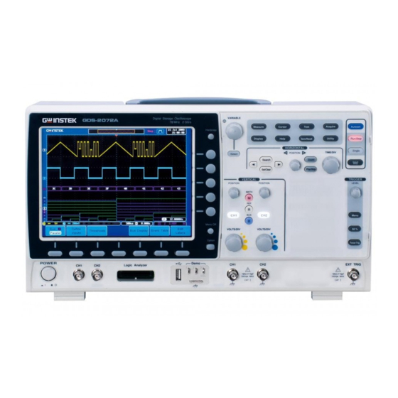
Page 17: Gds-2072A/2102A/2202A/2302A Front Panel
GETTING STARTED GDS-2072A/2102A/2202A/2302A Front Panel Function Variable knob Autoset, Run/Stop, Single keys and Select key and Default settings Horizontal GDS-2202A Digital Storage Oscilloscope VARIABLE 200 MHz 2 GS/s controls Visual Persistence Oscilloscope Measure Cursor Test Acquire Autoset Hardcopy Hardcopy key Display Help Save/Recall... - Page 18 GDS-2000A Series User Manual The Side menu and Bottom menu keys are used to Menu Keys make selections from the soft-menus on the LCD user interface. To choose menu items, use the 7 Bottom menu keys located on the bottom of the display panel.
- Page 19 GDS-2000A. Configures and runs automatic Measure Measure measurements. Configures and runs cursor Cursor Cursor measurements. Configures and runs GW Instek Test Test applications. Configures the acquisition mode, Acquire Acquire including Segmented Memory acquisition. Configures the display settings.
- Page 20 GDS-2000A Series User Manual Sets the acquisition mode to single Single Single triggering mode. Resets the oscilloscope to the Default Setup Default default settings. The horizontal controls are used to change the Horizontal position of the cursor, set the time base settings, Controls zoom into the waveforms and search for events*.
- Page 21 GETTING STARTED Use the Set/Clear key to set or Set/Clear Set/Clear clear points of interest when using the search function. The trigger controls are used to control the trigger Trigger Controls level and options. Used to set the trigger level. Level Knob LEVEL Used to bring up the trigger menu.
- Page 22 GDS-2000A Series User Manual Accepts external trigger signals External Trigger EXT TRIG (page 144). Input Input impedance: 1MΩ Voltage input: ±15V(peak), EXT trigger capacitance:16pF. Use the math key to set and MATH Math Key configure math functions. Press the Reference key to set or Reference Key remove reference waveforms.
- Page 23 GETTING STARTED The Demo outputs are Demo and Probe Demo multifunction outputs that can be Compensation Outputs configured for probe compensation, as a trigger output or as a basic waveform generator for demonstration purposes. (FM signal, UART, I C, SPI). By default, the 3 Demo outputs are configured as: 1: Trigger output...
-
Page 24: Rear Panel
GDS-2000A Series User Manual Rear Panel USB Device USB Host RS232 port port port Module Slot 1 Calibration output Module Slot 2 Ser. No. Label LINE VOLTAGE AC 100 240V RANGE CAUTION FREQUENCY 60Hz TO AVOID ELECTRIC SHOCK THE POWER CORD PROTECTIVE GROUNDING CONDUCTOR MUST BE CONNECTED TO GROUND. - Page 25 GETTING STARTED Used for RS-232-based remote RS232 Port control. Module Slots The module slots are used to install the optional modules: DS2-LAN: Ethernet and SVGA DS2-GPIB: GPIB GLA-08: 8 channel logic analyzer GLA-16: 16 channel logic analyzer Power cord socket accepts AC Power Input Socket mains, 100 ~ 240V, 50/60Hz.
-
Page 26: Display
GDS-2000A Series User Manual Display Channel Memory bar Trigger Status Acquisition mode Indicators Date and time Analog Trigger position Trigger level Waveforms Waveform Digital frequency waveforms Trigger configuration Channel status Horizontal status Shows the analog input signal waveforms. Analog Waveforms... - Page 27 GETTING STARTED Math indicator Shows the position of the trigger. Trigger Position Horizontal Status Shows the horizontal scale and position. Current date and time (page 170). Date and Time Shows the trigger level on the Trigger Level graticule. Memory Bar The ratio and the position of the displayed waveform compared with the internal memory (page...
- Page 28 GDS-2000A Series User Manual Indicates the frequency is less than 2Hz (lower frequency limit). Trigger source, slope, Trigger voltage, coupling. Configuration Horizontal scale, Horizontal Status horizontal position. For trigger details, see page 144. Channel 1, DC coupling, Channel Status 2V/Div.
-
Page 29: Set Up
GETTING STARTED Set Up Tilt Stand Tilt To tilt, pull the legs forward, as shown below. To stand the scope upright, push the legs back Stand under the casing as shown below. -
Page 30: Module Installation
GDS-2000A Series User Manual Module Installation The GDS-2000A has a number of optional modules Background that can be installed into the module slots on the rear panel. These modules must be installed before power up. The modules are not hot-swappable. Please ensure the... -
Page 31: Software Installation
A different activation key is required for each optional software package. For the latest files and information regarding the optional software packages, see the GW Instek website: www.gwinstek.com or contact your nearest distributor. 1. Install any hardware modules if needed. See Steps page 30 for installation details. -
Page 32: Power Up
GDS-2000A Series User Manual 5. The installation will complete in a few seconds. When finished a pop-up message will appear asking you to restart the GDS-2000A. 6. Restart the GDS-2000A. Power Up The GDS-2000A accepts line voltages of 100 ~ 240V Requirements at 50 or 60Hz. -
Page 33: First Time Use
GETTING STARTED First Time Use This section describes how to connect a signal, Background adjust the scale, and compensate the probe. Before operating the GDS-2000A in a new environment, run these steps to make sure the instrument performs at its full potential. Follow the procedures on the previous page. - Page 34 GDS-2000A Series User Manual Demo POSITION Demo Press the Autoset key. A square 6. Capture Signal Autoset waveform appears on the center of (Autoset) the screen. For Autoset details, see page 66. Press the Display key, and set the 7. Select Vector Display display to Vector on the bottom menu.
-
Page 35: How To Use This Manual
GETTING STARTED Under Over Normal Compensation Compensation 9. Start Operation Continue with the other operations. Measurement: page 64 Configuration: page 101 Save/Recall: page 185 File Utilities: page 211 Apps.: page 174 Hardcopy key: page 218 Remote Control: page Maintenance: page 241 How to Use This Manual This section describes the conventions used in this Background... - Page 36 GDS-2000A Series User Manual Active parameters are highlighted for each menu item. For example in the example below, Coupling is currently set to DC. If a menu item can be toggled from one value or parameter to another, the available options will be visible, with the current option highlighted.
- Page 37 GETTING STARTED 2. Press a side menu key to either set a parameter or to access a sub menu. 3. If accessing a sub menu or setting VARIABLE a variable parameter, use the Variable knob to scroll through menu items or variables. Use the Select key to confirm and exit.
- Page 38 GDS-2000A Series User Manual Toggling a Menu Parameter 1. Press the bottom menu key to toggle the parameter. Reduce Side Menu 1. To reduce the side menu, press the corresponding bottom menu that brought up the side menu. For example: Press the Source soft-key to...
- Page 39 GETTING STARTED Reduce Lower Menu GDS-2204A Digital Storage Oscilloscope VARIABLE 200 MHz 2 GS/s Visual Persistence Oscilloscope Measure Cursor Test Acquire Autoset Hardcopy Display Help Save/Recall Utility Run/Stop HORIZONTAL Single TIME/DIV Select POSITION 1. Press the relevant function Search Zoom Default Set/Clear key again to reduce the...
- Page 40 GDS-2000A Series User Manual GDS-2204A Digital Storage Oscilloscope VARIABLE 200 MHz 2 GS/s Visual Persistence Oscilloscope Measure Cursor Test Acquire Autoset Hardcopy Display Help Save/Recall Utility Run/Stop HORIZONTAL Single TIME/DIV Select POSITION 1. Press the Menu Off key to Search...
-
Page 41: Quick Reference
QUICK REFERENCE UICK REFERENCE This chapter describes the GDS-2000A menu tree, shortcuts to major operations, built-in Help access, and default factory settings. Use them as a handy reference to get a quick access to the functionality. Menu Tree / Operation Shortcuts ........43 Convention ................ - Page 42 GDS-2000A Series User Manual Utility Key – Wave Generator - Demo Outputs ..... 57 Search - Edge ................ 57 Search – Pulse Width ............58 Search - Runt ................ 58 Search – Rise/Fall Time ............59 Zoom Key ................59 Option Key ................
-
Page 43: Menu Tree / Operation Shortcuts
QUICK REFERENCE Menu Tree / Operation Shortcuts Convention For all menu trees, the bottom menu keys are shown as grey icons and side menu keys are shown in white. All menu tree operations are shown in order from top to bottom. Below is an example of the menu tree operation for the trigger source menu and a comparison to the operation on the DSO screen. -
Page 44: Acquire Key
GDS-2000A Series User Manual Acquire Key Sets the acquisition mode. Acquire Reset H Record Sample rate Mode Segments Length Position to 0s XXXMSPS Sample Auto OFF'YT( Peak Detect Sin(x)/x Short Triggered Average 2,4,8,16,32,64, 128,256 Digital Filter Off, 1% ~ 49%... -
Page 45: Autoset Key
QUICK REFERENCE Autoset Key Automatically finds the signal and sets the horizontal and vertical scale. Autoset Mode Undo Autoset Fit Screen AC Priority CH1 ~ 4 Key Set the channel input parameters. Position/ Set to 0 Coupling Impedence Invert Bandwidth Expand by Probe xxxV... -
Page 46: Cursor Key
GDS-2000A Series User Manual Cursor Key Set cursor positions. Cursor Set Cursor Set Cursor Positions As Positions As H Cursor V Cursor H Unit V Unit 100% 100% Base Activates menu Activates menu item ˚ item Display Key Set the display properties. -
Page 47: Math Key
QUICK REFERENCE Math Key Standard math and FFT functions. MATH Advanced Math Math Source 1 Source 1 Operator CH1~CH4 CH1~CH4 d/dt Ref1~Ref4 ∫dt Ref1~Ref4 √ Operator f(x) Source Vertical dBV RMS CH1~CH4 × Linear RMS Ref1~Ref4 ÷ Window f(x) Source 2 Source 2 Hanning Edit f(x) -
Page 48: Measure Key
GDS-2000A Series User Manual Measure Key Display automatic measurements either individually or as voltage/current, time or delay measurement groups. Measure Remove Gating Display All High-Low Statistics Measurement Measurement Source Statistics Select Auto Measurement (Full Record) CH1~CH4 Pk-Pk Math High-Low: Remove... -
Page 49: Hardcopy Key
QUICK REFERENCE Hardcopy Key Print screen images or save a waveform, screen Hardcopy image or setup (depending on the assigned function). Run/Stop Key Run/stop signal acquisition. Run/Stop REF Key R1ON/OFF R2ON/OFF R3ON/OFF R4ON/OFF Vertical Vertical Vertical Vertical Vertical scale Vertical scale Vertical scale Vertical scale Vertical position... -
Page 50: Save/Recall Key
GDS-2000A Series User Manual Save/Recall Key Save and recall images, waveforms and panel setups. Edit labels for reference and setup files. Save/Recall Recall Edit File Recall Save Image Save Waveform Save Setup Setup Waveform Label File Format From Label For... -
Page 51: Test Key
QUICK REFERENCE Test Key Use the Go-NoGo application as well as other optional software. Test APP. Go-NoGo Unistall Go-NoGo Goes to the Go-NoGo menu Test Key – Go-NoGo Compare Reference GoNo NG When Violating Enable Break Mode Source Auto Enter Stop Tolerance Disable... -
Page 52: Trigger Type Menu
GDS-2000A Series User Manual Trigger Type Menu Type Menu Edge Goes to the Edge Trigger menu Delay Goes to the Pulse Width Trigger Pulse Width menu Video Goes to the Video Trigger menu Others Goes to the Pulse Runt Trigger menu... -
Page 53: Trigger Delay Menu
QUICK REFERENCE Trigger Delay Menu Type Source Coupling Slope Level Delay Mode / Holdoff Delay Auto Time -XX~XXV 10.0ns ~ 10.0s Normal Set to TTL Holdoff Event Holdoff Reject 1.4V 1~65535 10.00ns ~ 10.0s Set to ECL Set to Set to -1.3V Minimum Minimum... -
Page 54: Trigger Pulse Runt Menu
GDS-2000A Series User Manual Trigger Pulse Runt Menu Type Source Polarity When Threshold Mode Holdoff Pulse Runt Auto > CH1~ CH4 10.0ns~10.0s -XX~XXV Normal < Set to EXT Probe ≠ Volt -XX~XXV Minimum Current Set to TTL 10.0ns~10.0s Alternate 1.4V Set to ECL -1.3V... -
Page 55: Utility Key
QUICK REFERENCE Utility Key Utility Data & File Utilities Language System Hardcopy Demo Output Time System Function USB Device Year Demo Mode English Create Folder Info 2XXX Port Print Analog Trad. Chinese Save Month Day UART Simp. Chinese Rename Ethernet Jan~Dec Ink Saver Korean... -
Page 56: Utility Key - I/O
GDS-2000A Series User Manual Utility Key – I/O USB Device RS-232C Ethernet Socket Server Port Computer Baud Rate Server Back Space Printer 2400, 4800, 9600, 19200, DHCP/BOOTP Current Port 38400, 57600, 3000 115200 Stop Bit Select Port Save Now 1, 2... -
Page 57: Utility Key - Wave Generator - Demo Outputs
QUICK REFERENCE Utility Key – Wave Generator - Demo Outputs Demo Output Demo Mode Analog UART Demo 1 Demo 1 Demo 1 Demo 1 SCLK SCLK Trigger Output Demo 2 Demo 2 Demo 2 Demo 2 Demo 3 Demo 3 Demo 3 Demo 3 Frequency... -
Page 58: Search - Pulse Width
GDS-2000A Series User Manual Search – Pulse Width Set the Search Function for pulse width events. Search Search Search Type Source Polarity When Threshold CH1~ CH4 Search Search > -XX~XXV Edge D0~D15 < Set to TTL Pulse Width Save All ≠... -
Page 59: Search - Rise/Fall Time
QUICK REFERENCE Search – Rise/Fall Time Set the Search function for rise and fall time events. Search Search Search Type Source Slope When Threshold > Search Search High CH1~ CH4 Edge < -XX~XXV Pulse Width Save All ≠ Runt -XX~XXV Marks Rise/Fall Time Set to TTL... -
Page 60: Option Key
GDS-2000A Series User Manual Option Key Accesses the functions in the Option menu. Option Logic Function Analyzer Generator Logic Goes to the Logic Analyzer menu Analyzer Function Goes to the Function Generator menu Generator Goes to the options I/O menu... -
Page 61: Default Settings
QUICK REFERENCE Default Settings Default The default factory installed settings can be recalled at any time by pressing the Default key. Mode: Sample XY: OFF Acquire Interpolation: Sin(x)/x Sample rate: 2GSPS Record Length: Auto Mode: Vector Persistence: 240ms Display Waveform intensity: 50% Graticule intensity: 50% Waveform visuals: Gray Graticule: full Scale: 100mV/Div CH1: On... - Page 62 GDS-2000A Series User Manual Coupling: DC Alternate: Off Rejection: Off Noise Rejection: Off Slope: Positive Level: 0.00V Mode: Auto Holdoff: 10.0ns Hardcopy: Save Ink Saver: Off Utility Assign Save To: Image File Format: Bmp Search: Off Search Segments: Off Segments...
-
Page 63: Built-In Help
QUICK REFERENCE Built-in Help The Help key accesses a context sensitive help menu. The help menu contains information on how to use the front panel keys. Panel Operation 1. Press the Help key. The Help display changes to Help mode. 2. -
Page 64: Measurement
GDS-2000A Series User Manual EASUREMENT Basic Measurement ............65 Channel Activation .............. 65 Autoset .................. 66 Run/Stop ................68 Horizontal Position/Scale ..........69 Vertical Position/Scale ............71 Automatic Measurement ..........72 Measurement Items ............. 72 Add Measurement ..............76 Remove Measurement ............78 Gated mode ................ -
Page 65: Basic Measurement
MEASUREMENT Basic Measurement This section describes the basic operations required in capturing and viewing the input signal. For more detailed operations, see the following chapters. Cursor Measurement → from page 85 Configuration → from page 101 Before operating the oscilloscope, please see the Getting Started chapter, page 10. -
Page 66: Autoset
GDS-2000A Series User Manual To activate the default state, Default Setup Default press Default. Autoset The Autoset function automatically configures the Background panel settings to position the input signal to the best viewing condition. The GDS-2000A automatically configures the following parameters. - Page 67 MEASUREMENT 1. Choose between Fit Screen Mode Change modes and AC Priority Mode from the bottom menu. 2. Press the Autoset key again to use Autoset Autoset in the new mode. Fit Screen Mode AC Priority Autoset does not work in the following situations. Limitation Input signal frequency is less than 20Hz ...
-
Page 68: Run/Stop
GDS-2000A Series User Manual Run/Stop By default, the waveform on the display is Background constantly updated (Run mode). Freezing the waveform by stopping signal acquisition (Stop mode) allows flexible observation and analysis. To enter Stop mode, two methods are available: pressing the Run/Stop key or using the Single Trigger mode. -
Page 69: Horizontal Position/Scale
MEASUREMENT The waveform can be moved or scaled in both Run Waveform Operation and Stop mode, but in different manners. For details, see page 130 (Horizontal position/scale) and page 137 (Vertical position/scale). Horizontal Position/Scale For more detailed configuration, see page 130. The horizontal position knob Set Horizontal POSITION... - Page 70 GDS-2000A Series User Manual The Time/Division rate is displayed to the left of the H icon at the bottom of the screen. The display bar indicates how much Display bar of the waveform is displayed on the screen at any given time. Changes to timebase will be reflected on the display bar.
-
Page 71: Vertical Position/Scale
MEASUREMENT Vertical Position/Scale For more detailed configuration, see page 137. To move the waveform up or Set Vertical POSITION down, turn the vertical position Position knob for each channel. As the waveform moves, the vertical position of the cursor appears on the display. The waveform can be moved Run/Stop mode... -
Page 72: Automatic Measurement
GDS-2000A Series User Manual Automatic Measurement The automatic measurement function measures and updates major items for Voltage/Current, Time, and Delay type measurements. Measurements can be made with both the analog channels and the digital channels*, however the digital channels are only limited to a select number of time measurements. - Page 73 MEASUREMENT Positive peak. Negative peak. Difference between the Amplitude global high and value and the global low value, measured over the entire waveform or gated region. (=high − low) Global high voltage. See High page 81 for details. Global low voltage. See page 81 for details.
- Page 74 GDS-2000A Series User Manual The Summation based on all Cycle Area data samples within the first cycle found in the gated region. Rise overshoot ROVShoot Fall overshoot FOVShoot Rise preshoot RPREShoot Fall preshoot FPREShoot Frequency of the waveform. Time Frequency Measurement Waveform cycle time.
- Page 75 MEASUREMENT Measures the number of -Pulses negative pulses. Measures the number of +Edges positive edges. Measures the number of -Edges negative edges. Time between: Delay Source 1 first rising edge and Measurement Source 2 first rising edge. Time between: Source 1 first rising edge and Source 2 first falling edge.
-
Page 76: Add Measurement
GDS-2000A Series User Manual The phase difference of two Phase signals, calculated in degrees. The in-built help system can be used to see detailed Note automatic measurement definitions. Add Measurement The Add Measurement function allows you to add up to eight automatic measurement items on the bottom of the screen from any channel source. - Page 77 MEASUREMENT Frequency, Period, RiseTime, Time FallTime, +Width, –Width, Duty Cycle, +Pulses, -Pulses, +Edges, - Edges FRR, FRF, FFR, FFF, LRR, LRF, LFR, Delay LFF, Phase 4. All measurements will be displayed in a window on the bottom of the screen. The channel number and channel color indicate the measurement source.
-
Page 78: Remove Measurement
GDS-2000A Series User Manual Remove Measurement Individual measurements can be removed at any time using the Remove Measurement function. 1. Press the Measure key. Remove Measure Measurement Item 2. Press Remove Measurement from the bottom menu. 3. Press Select Measurement and select the item that you want to remove from the measurement list. -
Page 79: Gated Mode
MEASUREMENT Gated mode Some automatic measurements can be limited to a “gated” area between cursors. Gating is useful for measuring a magnified waveform or when using a fast time base. The Gated mode has three possible configurations: Off (Full Record), Screen and Between Cursors. -
Page 80: Display All Mode
GDS-2000A Series User Manual Display All mode Display All mode shows and updates all items from Voltage and Time type measurements. 1. Press the Measure key. View Measure Measurement Results 2. Press Display All from the bottom menu. 3. Press Source from the side menu and choose a measurement source. -
Page 81: High Low Function
MEASUREMENT Delay type measurement is not available in this Delay Measurements mode as only one channel is used as the source. Use the Individual measurement mode (page 76) instead. Digital Channels Only Frequency, Period, +Width, -Width and Duty Cycle measurements are supported for digital channels. - Page 82 GDS-2000A Series User Manual Sets the high-low values as the Min-max measured minimum or maximum measured values. high 1. Press the Measure key. Set High-Low Measure 2. Press High-Low from the bottom menu. 3. Select the type of High-Low settings from the side menu.
-
Page 83: Statistics
MEASUREMENT Statistics The Statistics function can be used to view a Background number of statistics for the selected automatic measurements. The following information is displayed with the Statistics function: Currently measured value Value The mean value is calculated from Mean a number of automatic measurement results. - Page 84 GDS-2000A Series User Manual 3. Set the number of samples to be used in the mean and standard deviation calculations. 2~1000 Samples: 4. Press Statistics from the bottom menu and turn the Statistics function on. 5. The statistics will appear at the bottom of the display in a table.
-
Page 85: Cursor Measurement
MEASUREMENT Cursor Measurement Horizontal or vertical cursors are used to show the position and values of waveform measurements and math operation results. These results cover voltage, time, frequency and other math operations. When the cursors (horizontal, vertical or both) are activated, they will be shown on the main display unless turned off. - Page 86 GDS-2000A Series User Manual 4. The cursor position information appears on the top left hand side of the screen Hor. position, Voltage/Current Cursor Hor. position, Voltage/Current Cursor Delta (difference between cursors) dV/dt or dI/dt 5. Use the Variable knob to move the VARIABLE movable cursor(s) left or right.
- Page 87 MEASUREMENT FFT cursors use different vertical units. For FFT details, see page 96. Hor. position, dB/Voltage Cursor Hor. Position, dB/Voltage Cursor Delta (difference between cursors) dV/dt or d/dt Example Horizontal cursors XY mode cursors measure a number of X by Y XY Mode measurements.
- Page 88 GDS-2000A Series User Manual Delta (difference between cursors) Example Horizontal cursors...
-
Page 89: Use Vertical Cursors
MEASUREMENT Use Vertical Cursors 1. Press the Cursor key twice. Panel Operation/ Cursor Range 2. Press V Cursor from the bottom menu if it is not already selected. 3. When the V Cursor is selected, repeatedly pressing the V Cursor key or the Select key will toggle which vertical cursor is selected. - Page 90 GDS-2000A Series User Manual 5. Use the Variable knob to move the VARIABLE cursor(s) up or down. 6. To change the units of the vertical Select Units position, press V Unit. Base (source wave units), % (ratio) Units 7. To set the 0% and 100% ratio...
- Page 91 MEASUREMENT Example Horizontal cursors Vertical cursors XY mode cursors measure a number of X by Y XY Mode measurements. Rectangular, polar co-ordinates, Cursor product, ratio. Rectangular, polar co-ordinates, Cursor product, ratio. Delta (difference between cursors)
- Page 92 GDS-2000A Series User Manual Example Vertical cursors Horizontal cursors...
-
Page 93: Math Operation
MEASUREMENT Math Operation Overview Math operation runs addition, subtraction, Background multiplication, division, FFT, or certain advanced math functions for waveform manipulations using the input signals or reference waveforms (Ref1~4) and shows the result on the display. The resulted waveform characteristics can be measured using the cursors. -
Page 94: Addition/Subtraction/Multiplication/Division
GDS-2000A Series User Manual Performs a square root calculation. √ CH1~4, Ref1~4, f(x) Source Frequency resolution Good Hanning FFT Window Amplitude resolution Not good Frequency measurement on Suitable for..periodic waveforms Frequency resolution Good Hamming FFT Window Amplitude resolution Not good Frequency measurement on Suitable for.. - Page 95 MEASUREMENT 3. Select Source 1 from the side menu CH1~4, Ref~4 Range 4. Press Operator to choose the math operation. +, -, ×, ÷ Range 5. Select Source 2 from the side menu. CH1~4, Ref~4 Range 6. The math measurement result appears on the display.
-
Page 96: Fft
GDS-2000A Series User Manual –12.00 Div ~ +12.00 Div Range To change the unit/div settings, press Unit/div, then use the Variable knob to change the unit/div. The units that are displayed depend on which operator has been selected, and whether the probe for the selected channel has been set to voltage or current. - Page 97 MEASUREMENT 4. Press the Vertical Units key from the side menu to select the vertical units used. Linear RMS, dBV RMS Range 5. Press the Window key from the side menu and select the window type. Hanning, Hamming, Rectangular, Range and Blackman.
-
Page 98: Advanced Math
GDS-2000A Series User Manual Zoom and Offset To zoom into the FFT waveform, press Zoom until the x times parameter is highlighted and then use the Variable knob. 1x ~ 20x Range To horizontally offset the FFT waveform, press Zoom until the frequency parameter is highlighted and then use the Variable knob. - Page 99 MEASUREMENT 4. Select the Source from the side menu. CH1~4, Ref~4, f(x)* Range *the f(x) source is set with the Edit F(x) function, page 100. 5. The math result appears. For the differential/integral operations, the unit/div scale changes accordingly. Source Advanced Math Position and Unit To move the math waveform vertically, press Position and use the...
-
Page 100: Edit F(X)
GDS-2000A Series User Manual Edit F(x) The f(x) source is a user-defined math function that Background can be used as a source waveform for the FFT or advanced math functions. The f(x) source waveform is created by the addition, subtraction, multiplication or division of two input waveforms. -
Page 101: Configuration
CONFIGURATION ONFIGURATION Acquisition ..............103 Select Acquisition Mode ............ 103 Digital Filter ................ 105 Show Waveform in XY Mode .......... 106 Set the Sampling Mode ............108 Set the Record Length ............109 Segmented Memory Acquisition Overview ...... 111 Segments Display ............... 113 Set the Number of Segments .......... - Page 102 GDS-2000A Series User Manual Vertical View (Channel) ..........137 Move Waveform Position Vertically ....... 137 Select Vertical Scale ............137 Select Coupling Mode ............138 Input Impedance ..............139 Invert Waveform Vertically ..........139 Limit Bandwidth ..............140 Expand by Ground/Center ..........141 Select Probe Type ..............
-
Page 103: Acquisition
CONFIGURATION Acquisition The Acquisition process samples the analog input signals and converts them into digital format for internal processing. Select Acquisition Mode The acquisition mode determines how the samples Background are used to reconstruct a waveform. This is the default acquisition Sample mode. - Page 104 GDS-2000A Series User Manual 3. Select an acquisition mode from the side menu. 4. If Average was chosen, set the number of samples to be used for the average function. Mode Sample, Peak Detect, Average Average 2, 4, 8, 16, 32, 64, 128,...
-
Page 105: Digital Filter
CONFIGURATION Digital Filter The digital filter function can remove unwanted Background components, such as noise, from the desired signal. The filtering only functions during continuous acquisition using either the Sample or Peak detect mode. The cut-off frequency range and step resolution of the digital filter is expressed as a fraction of the underlying sample rate, as shown below. -
Page 106: Show Waveform In Xy Mode
GDS-2000A Series User Manual Show Waveform in XY Mode The XY mode maps the input of channel 1 to the Background input of channel 2. In 4 channel models, the input of channel 3 can be mapped to the input of channel 4. - Page 107 CONFIGURATION X-Y mode is split into two windows. The top window shows the signals over the full time range. The bottom window shows XY mode. To move the X Y waveform position, use the vertical position knob: Channel 1 knob moves the X Y waveform horizontally, Channel 2 knob moves the X Y waveform vertically.
-
Page 108: Set The Sampling Mode
GDS-2000A Series User Manual Cursors can be used with XY mode. XY Mode Page 85 See the Cursor chapter for details. Set the Sampling Mode The GDS-2000A has two types of sampling modes: Background ET (Equivalent Time) and Sin(x)/x interpolation. -
Page 109: Set The Record Length
CONFIGURATION The sampling rate will be shown on the bottom right- hand corner. Sampling Sample mode rate Set the Record Length The number of samples that can be stored is set by Background the record length. Record length is important in an oscilloscope as it allows longer waveforms to be recorded and/or allows higher sampling rates to be achieved when equivalent time sampling is... - Page 110 GDS-2000A Series User Manual Trigger Mode Channel Setting Single Normal Auto CH1 on CH2 on CH3 on CH4 on CH1, CH3 on CH1, CH4 on CH2, CH3 on CH2, CH4 on CH1, CH2 on 500k 500k CH3, CH4 on 500k...
-
Page 111: Segmented Memory Acquisition Overview
CONFIGURATION Segmented Memory Acquisition Overview The advanced segmented memory utility allows the scope memory to be divided into different segments. Each time the scope is triggered, it only acquires data for one segment of memory at a time. This allows you to optimize the scope memory to only perform signal acquisition during important signal events. - Page 112 GDS-2000A Series User Manual Segmented memory acquisition example: Segment Segment Segment Segment Segment Segment As shown below, the memory is divided into segments to increase the number of events that can be effectively captured with the same acquisition memory. Also notice that the scope doesn’t need to rearm the trigger between each segment, this makes the segmented memory function especially useful for high speed signals.
-
Page 113: Segments Display
CONFIGURATION Segments Display Run/Stop Indicator Progress Indicator Indicates the number of Progress Indicator segments that have to been captured relative to the set number of segments. Stop: The segments have finished Run/Stop Indicator acquiring or have been stopped. Run: The scope is ready to acquire segments. -
Page 114: Set The Number Of Segments
GDS-2000A Series User Manual Set the Number of Segments Before the Segment function can be used, set the Note trigger settings as appropriate for the signal you wish to use. Panel Operation 1. Press the Acquire key. Acquire 2. Press Segments on the bottom menu. - Page 115 CONFIGURATION The first time Segmented memory is turned on the Note segments will automatically be run. Each segment will be automatically captured. The progress of capturing the segments is shown at the top of the display. 2. The scope will automatically start acquiring segments.
-
Page 116: Navigate Segmented Memory
GDS-2000A Series User Manual 1. To rerun the segments, press the Segments Stop Rerun Segmented Acquisition key to toggle the mode back to the Segments Run mode. Alternatively, press the Run/Stop Run/Stop key again. 2. Repeat steps 3 and 4 in the section above when the segmented acquisition has completed. -
Page 117: Play Through Each Segment
CONFIGURATION 3. The position in time of the selected segment relative to the time of the first segment is shown in the Segments Time key. Play Through Each Segment When the all the segments have been acquired, the Background play/pause key can be used to play back through each segment. -
Page 118: Segment Measurement
GDS-2000A Series User Manual Segment Measurement The Segmented memory function can be used in Background conjunction with the automatic measurements in the Measurement menu. Please note that digital channels are not supported for measurement using segments. Display All The Display All function will show all the acquired segments simultaneously. -
Page 119: Automatic Measurement
CONFIGURATION 3. The display will show all the acquired segments on the display simultaneously. The currently selected segment will be superimposed over the top for reference purposes. Example Automatic Measurement The Segments Measure function allows you to Background view automatic measurements for the segments in statistical bins or as a list displaying the result of each automatic measurement. - Page 120 GDS-2000A Series User Manual Puts all the measurement Measurement results for a segment in a list. List All the currently selected automatic measurement results are listed. A maximum of 8 automatic measurements can be used with this function. To use automatic measurements with the...
- Page 121 CONFIGURATION 4. The statics table or measurement list appears on the display. Note that the more segments that you have, the longer it will take to calculate the statics or list the measurement results. 5. For statistic measurements, press Plot Source to choose which automatic measurement to use for the statistics calculations.
- Page 122 GDS-2000A Series User Manual Example: Statistics Bin count Select cursor Statistics of currently selected bin Puts all the measurement results for a segment in a Measurement list. List 1. Press Select and use the variable Setup knob to scroll through each segment.
-
Page 123: Segment Info
CONFIGURATION Segment Info 1. Press Analyze Segments from the Operation bottom menu. Note: This key will only be available in the Stop mode. 2. Press Segments Info. 3. A table showing all general setting information for the segmented memory acquisitions is shown on the display. -
Page 124: Display
GDS-2000A Series User Manual Display The Display menu defines how the waveforms and parameters appear on the main LCD display. Display Waveform as Dots or Vectors When the waveform is displayed on screen, it can Background be displayed as dots or vectors. -
Page 125: Set The Level Of Persistence
CONFIGURATION Set the Level of Persistence The persistence function allows the GDS-2000A to Background mimic the trace of a traditional analog oscilloscope. A waveform trace can be configured to “persist” for designated amount of time. Panel Operation 1. Press the Display menu key. Display 2. - Page 126 GDS-2000A Series User Manual 0~100% Range 4. To set the graticule intensity, press Graticule Graticule Intensity from the side menu and edit the Intensity intensity value. 10~100% Range Example Waveform Intensity 0% Waveform Intensity 100% Graticule Intensity 10% Graticule Intensity 100%...
-
Page 127: Set The Waveform Intensity Type
CONFIGURATION Set the Waveform Intensity Type The intensity gradient of a signal can be set to Background grayscale or color. If intensity is set to color, the intensity gradient is analogous to a thermal color gradient where high intensity areas are colored red and low intensity areas are colored blue. -
Page 128: Select Display Graticule
GDS-2000A Series User Manual Select Display Graticule Panel Operation 1. Press the Display menu key. Display 2. Press Graticule from the bottom menu. 3. From the side menu choose the graticule display type. Full : Shows the full grid; X and Y axis for each division. -
Page 129: Freeze The Waveform (Run/Stop)
CONFIGURATION Freeze the Waveform (Run/Stop) For more details about Run/Stop mode, see page 68. Panel Operation 1. Press the Run/Stop key. The Run/Stop Run/Stop Run/Stop key turns red and waveform acquisition is paused. 2. The waveform and the trigger freezes. The trigger indicator on the top right of the display shows Stop. -
Page 130: Horizontal View
GDS-2000A Series User Manual Horizontal View This section describes how to set the horizontal scale, position, and waveform display mode. Move Waveform Position Horizontally POSITION Panel Operation The horizontal position knob moves the waveform left/right. As the waveform moves, a position indicator on the on the top of the display indicates the horizontal position of the waveform in memory. -
Page 131: Select Horizontal Scale
CONFIGURATION Select Horizontal Scale TIME/DIV To select the timebase (scale), turn the Select Horizontal Scale TIME/DIV knob; left (slow) or right (fast). Range 1ns/div ~ 100s/div, 1-2-5 increment The timebase indicator updates as the TIME/DIV is adjusted. Horizontal Time base position In Run mode, the memory bar and waveform size Run Mode... -
Page 132: Select Waveform Update Mode
GDS-2000A Series User Manual Select Waveform Update Mode The display update mode is switched Background automatically or manually according to the timebase and trigger. Updates the whole displayed waveform at Normal once. Automatically selected when the timebase (sampling rate) is fast. -
Page 133: Zoom Waveform Horizontally
CONFIGURATION Zoom Waveform Horizontally When in Zoom mode, the screen is split into 2 Background sections. The top of the display shows the full record length, with the bottom of the screen showing the normal view. Panel Operation 1. Press the Zoom key. Zoom 2. - Page 134 GDS-2000A Series User Manual To increase the zoom range, use the Zoom TIME/DIV TIME/DIV knob. The zoom time base (Z) at the bottom of the screen will change accordingly. Use the Horizontal Position knob to pan Move the Zoom POSITION the zoom window horizontally.
-
Page 135: Play / Pause
CONFIGURATION Play / Pause The Play/Pause key can be used to play through Background signals in Zoom mode. If the Segmented memory function is turned on, Note pressing the play pause key will play through memory segments. See page 117 for information. Panel Operation 1. - Page 136 GDS-2000A Series User Manual To increase the zoom range, use the Zoom TIME/DIV TIME/DIV knob. The zoom time base (Z) at the bottom of the screen will change accordingly. To alter the scrolling speed of the Scroll Speed zoom window, press the Zoom Position key to toggle the scrolling speed.
-
Page 137: Vertical View (Channel)
CONFIGURATION Vertical View (Channel) This section describes how to set the vertical scale, position, and coupling mode. Move Waveform Position Vertically POSITION Panel Operation 1. To move the waveform up or down, turn the vertical position knob for each channel. 2. -
Page 138: Select Coupling Mode
GDS-2000A Series User Manual The vertical scale indicator on the bottom left of the display changes accordingly for the specific channel. 1mV/div ~ 10V/div (1MΩ). 1-2-5 Range increments In Stop mode, the vertical scale setting can be Stop Mode changed. -
Page 139: Input Impedance
CONFIGURATION DC coupling AC coupling Input Impedance The input impedance of the GDS-2000A is fixed at Background 1MΩ. The impedance is displayed in the channel menu. View Impedance 1. Press the Channel key. 2. The impedance is displayed in the bottom menu. -
Page 140: Limit Bandwidth
GDS-2000A Series User Manual Limit Bandwidth Bandwidth limitation puts the input signal into a Background selected bandwidth filter. This function is useful for cutting out high frequency noise to see a clear waveform shape. The bandwidth filters available are dependent on the bandwidth of the oscilloscope model. -
Page 141: Expand By Ground/Center
CONFIGURATION Expand by Ground/Center When the voltage scale is changed, the Expand Background function designates whether the signal expands from the center of the signal or from the signal ground level. Expand by center can be used to easily see if a signal has a voltage bias. Expand by ground is the default setting. -
Page 142: Select Probe Type
GDS-2000A Series User Manual Expand by Ground Expand by Center Expand by Ground Expand by Center Select Probe Type A signal probe can be set to voltage or current. Background Panel Operation 1. Press the Channel key. 2. Press Probe from the bottom menu. -
Page 143: Set The Deskew
CONFIGURATION 3. Press Attenuation on the side menu and use the Variable knob to set the attenuation. Alternatively, press Set to 10X. 1mX ~1kX (1-2-5 step) Range The attenuation factor adds no influence on the real Note signal. It just changes the voltage/current scale on the display. -
Page 144: Trigger
GDS-2000A Series User Manual Trigger The trigger configures the conditions for when the GDS-2000A captures a waveform. The following trigger overview only applies to the analog channels, for triggering details using the optional logic analyzer module, please see the GDS-2000A Options User Manual for details. - Page 145 CONFIGURATION Delay trigger example (by time) Ext. trigger input Source Delay time length First triggering point Triggers when the pulse width (Glitch) of the Pulse Width (Glitch) signal is less than, equal, not equal or greater than a specified pulse width (Glitch). Pulse width Extracts a sync pulse from a video format signal, Video...
- Page 146 GDS-2000A Series User Manual Triggers when the signal stays high, low or either Timeout for a designated amount of time. The trigger level determines when a signal is high or low. Trigger level threshold Timer Triggering point...
-
Page 147: Trigger Parameter Overview
CONFIGURATION Trigger Parameter Overview All the following parameters are common for all the trigger types unless stated otherwise. Channel 1 ~ 4 input signals Trigger Source CH1 ~ 4 External trigger input EXT TRIG signal AC mains signal AC Line Alternate between channel sources for Alternate the trigger source. - Page 148 GDS-2000A Series User Manual DC coupling. Coupling (Edge, Delay) AC coupling. Blocks DC components from the trigger circuits. High frequency filter above 100kHz HF reject Low frequency filter below 5kHz LF reject Reject noise DC coupling with low sensitivity to reject noise.
- Page 149 CONFIGURATION Sets the number of events (1 ~ 65535) Event passed after the trigger event, until the real trigger timing. Sets the source trigger to the minimum Set to time. Minimum Sets the pulse width (10ns ~ 10s) and the triggering When condition.
- Page 150 GDS-2000A Series User Manual (Video) 1 or 2 or all. Field 1~263 for NTSC Line 1~313 for PAL/SECAM Sets the upper threshold limit. Threshold (Pulse Runt) Sets the lower threshold limit. 1.4V Set to TTL -1.3V Set to ECL Sets the High threshold.
-
Page 151: Setup Holdoff Level
CONFIGURATION Setup Holdoff Level The holdoff function defines the waiting period Background before the GDS-2000A starts triggering again after a trigger point. The holdoff function ensures a stable display if there are a number points in a periodic waveform that can be triggered. Holdoff applies to all the triggering types. -
Page 152: Setup Trigger Mode
GDS-2000A Series User Manual Setup Trigger Mode The trigger mode can be set to Normal or Auto Background (untriggered roll). The triggering mode applies to all the trigger types. See page 132. Panel Operation 1. Press the Trigger menu key. - Page 153 CONFIGURATION 5. Use the side menu to select the trigger source type. Channel 1 ~ 4 (Alternate On/Off), Range EXT (Ext Probe: Volt/Current, Attenuation: 1mX~1kX ), AC Line 6. Press Coupling from the bottom bezel menu to select the trigger coupling or frequency filter settings.
-
Page 154: Using Advanced Delay Trigger
GDS-2000A Series User Manual 12. Set the external trigger level using the side menu. 00.0V~ 5 screen divisions Range Set to TTL 1.4V Set to ECL -1.3V Set to 50% Using Advanced Delay Trigger The EXT trigger source is always used as the delay Background triggering source. -
Page 155: Using Pulse Width (Glitch) Trigger
CONFIGURATION 5. To Delay by Time (Duration), press Time from the side menu and set the delay time. 10ns ~ 10s (by time) Range Set to minimum 6. To Delay by Event, press Event from the side menu and set the number of events. - Page 156 GDS-2000A Series User Manual 5. Use the side menu to select the pulse width (glitch) trigger source. Channel 1 ~ 4 (Alternate On/Off), Range EXT (Ext Probe: Volt/Current, Attenuation: 1mX~1kX ), AC Line 6. Press Polarity to toggle the polarity type.
-
Page 157: Using Video Trigger
CONFIGURATION Using Video Trigger Panel Operation 1. Press the trigger Menu key. Menu 2. Press the Type key from the lower bezel menu. 3. Select Video from the side menu. The video trigger indicator appears at the bottom of the display. From left: source, video standard, field, line, coupling 4. -
Page 158: Pulse Runt Trigger
GDS-2000A Series User Manual 7. Press Trigger On to edit the video field and line. Use the side menu to select the field and line. 1, 2, All Field Video line NTSC: 1 ~ 262 (Even), 1 ~ 263 (Odd) - Page 159 CONFIGURATION Channel 1 ~ 4 Range 5. Press Polarity to toggle the polarity. Rising edge, falling edge, either. Range 6. Press When from the lower menu. Then use the side menu to select the condition and width. Condition > , < , = , ≠ 10ns ~ 10s Width 7.
-
Page 160: Using Rise And Fall (Slope) Trigger
GDS-2000A Series User Manual Using Rise and Fall (Slope) Trigger Panel Operation 1. Press the trigger Menu key. Menu 2. Press the Type key from the lower bezel menu. 3. Select Others Rise and Fall from the side menu. -
Page 161: Using The Timeout Trigger
CONFIGURATION 7. Press Threshold from the lower bezel to edit the High and Low threshold. High: -XXV~XV Range Low: -XXV~XXV Set to TTL 1.4V Set to ECL -1.3V Using the Timeout Trigger Panel Operation 1. Press the trigger Menu key. Menu 2. - Page 162 GDS-2000A Series User Manual 5. Press Trigger When from the lower menu. Then use the side menu to select trigger conditions. Condition Stays High, Stays Low, Either 6. Press Level from the lower bezel to set the trigger level. -XXV~XXV Range Set to TTL 1.4V...
-
Page 163: Search
CONFIGURATION Search The search feature can be used to search for events on both the analog and digital input channels. The events that can be searched for are similar to the events that are used for the trigger system. The only difference is that the search feature uses the measurement threshold levels rather than the trigger level to determine events. - Page 164 GDS-2000A Series User Manual Search Event Edge, Pulse Width, Pulse Runt, Rise and Fall Times, Types Logic*, Bus* *Requires the Logic Analyzer option. Panel Operation 1. Press the Search menu key. Search 2. Press Search from the bottom menu and turn the Search function on.
-
Page 165: Copying Search Event To/From Trigger Events
CONFIGURATION Copying Search Event To/From Trigger Events As the trigger system and search feature have Background similar settings, their settings can be used interchangeably by using the Copy functions. Interchangeable Edge, Pulse Width, Pulse Runt, Rise and Fall Times, Settings Logic, Bus Panel Operation 1. -
Page 166: Save Search Marks
GDS-2000A Series User Manual 2. Search events are marked by hollow white triangles at the top of the graticule. 3. Use the search arrow keys to move between each search event. Search events can be navigated in both stop and run mode. -
Page 167: Setting/Clearing Single Search Events
CONFIGURATION To clear all the saved marks, press Clear All Marks Clear All Marks from the side menu. Each time the Save All Marks function is used, the Note previously saved marks will also be retained, unless cleared. Setting/Clearing Single Search Events In addition to searching for search events based on Background Search Type settings, custom search marks can be... -
Page 168: System Info / Language / Clock
GDS-2000A Series User Manual System Info / Language / Clock This section describes how to set the interface, beeper, language, time/date, and probe compensation signal. Select Menu Language The following is a list of the languages available by Parameter default. Language selection may differ according to the region. -
Page 169: View System Information
CONFIGURATION View System Information Panel Operation 1. Press the Utility key. Utility 2. Press System from the lower menu. 3. Press System Info from the side menu. A display panel will appear showing: Manufacturer name Model name Serial number Firmware version ... -
Page 170: Turn The Buzzer On/Off
GDS-2000A Series User Manual Panel Operation 1. Press the Utility key. Utility 2. Press System from the lower menu. 3. Press Erase Memory from the side menu. A message will prompt you to press Erase Memory again to confirm the process. - Page 171 CONFIGURATION 3. Set the Year, Month, Day, Hour and Minute from the side menu. 2000 ~ 2037 Year 1 ~ 12 Month 1 ~ 31 1~23 Hour 0~59 Minute 4. Press Save Now from the side menu to save the date and time. 5.
- Page 172 GDS-2000A Series User Manual Waveforms Mode Demo Outputs Outputs Trigger Output Analog Demo 1 Pulse Signal: Burst frequency: 100kHz, Burst duration: 500uS (50 pulses) Burst Period: 1mS FM: 100kHz~1MHz Demo 2 Probe Compensation output, Demo 3 1kHz~200kHz, Duty Cycle 5%~95%...
- Page 173 CONFIGURATION 3. Press Demo Mode from the side menu and select the mode for the Demo outputs. The actual output waveform for each demo output is listed in the side menu. Trigger Output Usage: Note To use the DEMO 1 Trigger Output signal, an input signal should first be connected to one of the input channels (CH1, 2, 3 or 4), otherwise no Trigger Output signal will be shown.
-
Page 174: Optional Software And Apps
GDS-2000A Series User Manual PTIONAL SOFTWARE and APPS. Applications ..............175 Overview ................175 Running Applications ............175 Uninstalling Applications ..........176 Using Go-NoGo ..............177 Optional Software ............182 Activating Optional Software ........... 182 Running Optional Software ..........182... -
Page 175: Applications
OPTIONAL SOFTWARE and APPS. Applications Overview The APP. function allows different applications to Background be run. Applications can be downloaded from the GW Instek website. The Go/No-Go application can be Included Go/No-Go used to set threshold boundaries Applications for input signals. Go/No-Go... -
Page 176: Uninstalling Applications
GDS-2000A Series User Manual 3. Scroll through each application using the Variable knob. 4. Select an application by pressing Select the Select key twice. ×2 Uninstalling Applications Any app can be easily uninstalled using the Background Uninstall function. Panel Operation 1. Press the Test key. -
Page 177: Using Go-Nogo
OPTIONAL SOFTWARE and APPS. 3. Scroll through each application using the Variable knob. 4. When the desired application is highlighted, press Uninstall to begin the uninstallation. Press ×2 again to confirm. Using Go-NoGo The Go-NoGo test checks if a waveform fits inside Background a user-specified maximum and minimum boundary. - Page 178 GDS-2000A Series User Manual Choose the Go_NoGo application from the APP. menu. See page 175. Select the Go-NoGo conditions (NG When) and Set Go-NoGo actions when a Go-NoGo condition has been met Conditions (Violating). 1. Press NG When from the bottom...
- Page 179 OPTIONAL SOFTWARE and APPS. 2. Press Go Back to return to the previous menu. 1. Press Compare Source from the Set Go-NoGo bottom menu to set the Go-NoGo Source boundary source. Sets CH1 as the source. Sets CH2 as the source. Sets CH3 as the source.
- Page 180 GDS-2000A Series User Manual Voltage division range Range 4. Press Save Operation to save the Save Boundary tolerance boundaries. Template 5. The Maximum Position tolerance will be saved to reference waveform R1, and the Minimum Position tolerance to R2. 6. Press Go Back to return to the previous menu.
- Page 181 OPTIONAL SOFTWARE and APPS. Maximum Tolerance position Ratio: fail / test Minimum position To exit the application, press Break. Exit the Application To output the Go-NoGo results to an Using the Go- external device, the Go-NoGo rear NoGo Output panel terminal (open collector) can be used.
-
Page 182: Optional Software
A different activation key is required for each optional software package. For the latest files and information regarding the optional software packages, see the GW Instek website: www.gwinstek.com or contact your nearest distributor. Please see page 30 for details on how to install... -
Page 183: Uninstalling Optional Software
OPTIONAL SOFTWARE and APPS. 2. Select the relevant option from the bottom menu. If an option is not installed, it will be grayed- out. 3. Please see the GDS-2000A Options User Manual for how to use the optional software functions. Uninstalling Optional Software Optional software packages such can be Background... - Page 184 GDS-2000A Series User Manual 4. Press Option Uninstall on the side menu. 5. Select the optional software packages that you wish to uninstall from the side menu. 6. Use the Up and Down arrows on the side menu to select an option to uninstall.
-
Page 185: Save/Recall
SAVE/RECALL AVE/RECALL File Format/Utility ............186 Image File Format .............. 186 Waveform File Format ............186 Spreadsheet File Format............ 187 Setup File Format ............... 189 Create/Edit Labels ............191 Save ................195 File Type/Source/Destination ......... 195 Save Image ................196 Save Waveform .............. -
Page 186: File Format/Utility
GDS-2000A Series User Manual File Format/Utility Image File Format DSxxxx.bmp or DSxxxx.png Format The display image is 800 by 600 pixels. The Contents background color can be inverted (Ink saver function). Each image file is saved to the current file path as a bitmap or PNG file. -
Page 187: Spreadsheet File Format
SAVE/RECALL Reference waveforms stored in the Ref 1~4 internal memory, separate from W1 ~ W20. Reference waveforms (Ref 1 ~ 4) can be displayed directly onto the display with amplitude and frequency information. Ref 1~4 are useful for reference purposes. Other waveforms ( LSF and W1~20) must be recalled to R1~4 before being displayed. - Page 188 GDS-2000A Series User Manual entire long memory length (See page 109 for information on the record length). All points are recorded as integers. Note, however, that only fast CSV can be recalled to the internal memory. Detailed CSV, LM Fast CSV and LM Detailed CSV cannot be recalled.
-
Page 189: Setup File Format
SAVE/RECALL & Format Memory length LM Fast CSV (scope type) IntpDistance Trigger address (input trigger distance) Trigger level Source Vertical units Vertical units div Vertical units extend Label Probe type Probe ratio ... - Page 190 GDS-2000A Series User Manual Mode Graticule Display intensity Persistence Waveform Waveform visuals intensity Graticule Scale Expand Channel Channel Position Coupling Probe Impedance Probe attenuation Invert ...
-
Page 191: Create/Edit Labels
SAVE/RECALL Image file Data file format Save/ format recall Create/Edit Labels Reference files, Setup files and the analog input Overview channels can have individual file labels set. For the analog channels and reference waveforms, the file label can be displayed next to the channel/reference indicator. - Page 192 GDS-2000A Series User Manual When using the optional Logic Analyzer, labels can Note also be set for the digital channels. Please see the GDS-2000A Options User Manual for details. The labels for digital channels cannot be edited from the Save/Recall menu.
- Page 193 SAVE/RECALL 2. The Edit Label window appears. 3. Use the Variable knob to highlight a character. VARIABLE Press Enter Character to select a number or letter. Press Back Space to delete a character. Press Editing Completed to save the label and return to the previous menu.
- Page 194 GDS-2000A Series User Manual To display the currently selected Display Label file label on the screen next to its respective indicator, toggle Label Display to On. Conversely, if you want to remove the currently selected file label from the display, toggle Label...
-
Page 195: Save
SAVE/RECALL Save File Type/Source/Destination Item Source Destination Front panel Internal memory: Set1 ~ Panel Setup settings Set20 (DSxxxx.set) File system: Disk, USB Channel 1 ~ 4 Internal memory: Waveform Data (DSxxxx.csv) Reference waveform Math operation ... -
Page 196: Save Image
GDS-2000A Series User Manual Save Image Images can be saved either using the Save/Recall key or by using the Hardcopy key. To save images using the Hardcopy key, see the hardcopy section on page 218. Panel Operation 1. To save to USB, connect a... - Page 197 SAVE/RECALL Ink Saver On Ink Saver Off 6. Press Save Now from the side menu to save the display as an image file. The file will not be saved if the power Note is turned off or the USB drive is taken out before the message ends.
-
Page 198: Save Waveform
GDS-2000A Series User Manual Save Waveform Panel Operation 1. To save to an external USB Front Rear flash drive, connect the Host drive to the front or rear panel USB port. If a USB drive is not connected, files will be saved to the internal memory. - Page 199 SAVE/RECALL 6. Press Save Now to confirm saving. When completed, a message appears at the bottom of the display. The file will not be saved if the power Note is turned off or the USB drive is taken out before the message ends. To edit USB flash drive contents USB File Utility (create/ delete/ rename files and...
-
Page 200: Save Setup
GDS-2000A Series User Manual Save Setup Panel Operation 1. (For saving to an external Front Rear USB flash drive) Connect Host the drive to the front or rear panel USB port. If a USB drive is not connected, files will be saved to the internal memory. - Page 201 SAVE/RECALL 5. Press Save Now to confirm saving. When completed, a message appears at the bottom of the display. The file will not be saved if the power Note is turned off or the USB drive is taken out before the message ends. To edit USB flash drive contents USB File Utility (create/ delete/ rename files and...
-
Page 202: Recall
GDS-2000A Series User Manual Recall File Type/Source/Destination Item Source Destination Factory installed Current front panel Default Panel setting Setup Internal memory: Current front panel Reference Ref1~4 Waveform Internal memory: S1 ~ Current front panel Panel Setup ... - Page 203 SAVE/RECALL Setting Contents The following is the default (factory) setting contents. Mode: Sample XY: OFF Acquire Sample mode: Sinc Sample rate: 2GSPS Digital filter: Off Record Length: Auto Mode: Vector Persistence: 16ms Display Waveform intensity: 50% Graticule intensity: 50% Waveform visuals: Gray Graticule: full Scale: 100mV/Div CH1: On Channel...
- Page 204 GDS-2000A Series User Manual Rejection: Off Noise Rejection: Off Slope: rising Level: 0.00V Mode: Auto Holdoff: 10.0ns Language: English Hardcopy key: Save Utility Ink Saver: Off File Format: BMP Assign Save To: Image Buzzer: Off Image file format: Bmp Data file format: LSF...
-
Page 205: Recall Waveform
SAVE/RECALL Recall Waveform Panel Operation 1. For recalling from an Front Rear external USB flash drive, Host connect the drive to the front or rear panel USB port. Only one host connection, front or rear, is allowed at a Note time. -
Page 206: Recall Setup
GDS-2000A Series User Manual *Only files in the current file path will be available, this includes files saved in the ALLXXX directories. Allxxxx.csv files cannot be recalled to the oscilloscope. Only the “fast CSV” files can be recalled to the oscilloscope. - Page 207 SAVE/RECALL Only one host connection, front or rear, is allowed at a Note time. The USB Device port on the rear panel cannot be used concurrently with the USB Host port on the rear panel. 2. Press the Save/Recall key. Save/Recall 3.
- Page 208 GDS-2000A Series User Manual To edit labels for Setup files, press Edit Edit Label label. For more details on editing labels, see page 191.
-
Page 209: Reference Waveforms
SAVE/RECALL Reference Waveforms Recall and Display Reference Waveforms Panel Operation A reference waveform must be stored in advance. See page 198 to store waveforms as reference waveforms. 1. Press the REF key on the front panel. 2. Pressing R1~R4 repeatedly will toggle the corresponding reference waveform OFF/ON. - Page 210 GDS-2000A Series User Manual Press Vertical repeatedly from the side Vertical Navigation menu to choose to edit the vertical position or Unit/Div. Use the Variable knob to edit the values. Press Horizontal repeatedly from the Horizontal side menu to choose to edit the Navigation Time/Div or the horizontal position.
-
Page 211: File Utilities
FILE UTILITIES ILE UTILITIES The file utilities are used each time files need to be saved to internal or external memory. The file utilities can create directories, delete directories, rename files as well as copy files from internal memory to USB. The File Utilities menu also sets the file path for saving and recalling files from the Save/Recall menu. - Page 212 GDS-2000A Series User Manual File Navigation The File Utilities menu can be used to choose files or to set the file path for saving/recalling files. File System File path Drive space File cursor File attributes Panel Operation 1. Press the Utility key.
- Page 213 FILE UTILITIES 3. The file system appears. 4. Use the Variable knob to move the VARIABLE file cursor up and down. Use the Select key to choose a file or directory or to set the file path. Select When a USB flash drive is used, ...
- Page 214 GDS-2000A Series User Manual Create Folder Panel Operation 1. Press the Utility key. Utility 2. Press File Utilities from the bottom menu. 3. Use the Variable knob and select key to navigate the file system. 4. Press Create Folder to make a new Create Folder directory at the selected location.
- Page 215 FILE UTILITIES 6. Press Editing completed to create the folder name. Press Cancel to cancel the operation. Cancel Rename File Panel Operation 1. Press the Utility key. Utility 2. Press File Utilities from the bottom menu. 3. Use the Variable knob and select key to choose a file to rename.
- Page 216 GDS-2000A Series User Manual Press Enter Character select a number or letter. Press Back Space to delete a character. 6. Press Editing completed to rename the folder or file. Delete File Panel Operation 1. Press the Utility key. Utility 2. Press File Utilities from the bottom menu.
- Page 217 FILE UTILITIES Copy File to USB Panel Operation 1. Connect a USB drive to the Front Rear front or rear panel USB port. . Host Only one host connection, front or rear, is allowed at a Note time. The USB Device port on the rear panel cannot be used concurrently with the USB Host port on the rear panel.
-
Page 218: Hardcopy Key
GDS-2000A Series User Manual ARDCOPY KEY The Hardcopy key is used as quick-save or quick-print key. The Hardcopy key can be assigned either to printout screenshots or to save files. When assigned to “Print” the screen image can be printed to a PictBridge compatible printer using the USB device port. - Page 219 HARDCOPY KEY 4. Press USB Device Port from the side menu and select Printer. Print Output Ensure the USB port has been configured to the printer before trying to print, see page 218. Panel Operation 1. Press the Utility key. Utility 2.
- Page 220 GDS-2000A Series User Manual Save - Hardcopy Key When the Hardcopy key is assigned to “Save”, Background pressing the Hardcopy key can be used to save a screen shot, a waveform, or the current setup, depending on the configuration. Panel Operation 1. If you wish to save to USB,...
- Page 221 HARDCOPY KEY 6. Press the Hardcopy key to save the Hardcopy file*. A message will appear when the save is successful. 1. For image files the file format can Image File Format be selected with the File Format key. BMP, PNG Format: 2.
-
Page 222: Remote Control Config
GDS-2000A Series User Manual EMOTE CONTROL CONFIG This chapter describes basic configuration for remote control. For a command list, refer to the programming manual downloadable from GWInstek website, www.gwinstek.com Interface Configuration ..........223 Configure USB Interface........... 223 Configure RS-232C Interface ........... 224 Configure the Ethernet Interface ........ -
Page 223: Interface Configuration
5. When the PC asks for the USB driver, select the USB driver included on the accompanying User Manual CD or download the driver from the GW Instek website, www.gwinstek.com, in the GDS-2000A product corner. The driver automatically sets the GDS-2000A as a serial... -
Page 224: Configure Rs-232C Interface
GDS-2000A Series User Manual Configure RS-232C Interface DB-9, Male RS-232C Connector Configuration 2400, 4800, 9600, 19200, 38400, Baud rate 57600, 115200 None, Odd, Even Parity 8 (fixed) Data bit 1, 2 Stop bit Panel Operation 1. Press the Utility key. -
Page 225: Configure The Ethernet Interface
REMOTE CONTROL CONFIG 7. Press Save Now to save the settings. 8. Connect the RS-232C cable to the rear panel port: DB-9 male connector. For a functionality check, see page 230. 2: RxD (Receive data) Pin Assignment 1 2 3 4 5 3: TxD (Transmit data) 5: GND 6 789... - Page 226 GDS-2000A Series User Manual The Ethernet interface is used for remote Background configuration of the oscilloscope over a network using the integrated web server or for remote control using a socket server connection. For details, please see the Web Server Configuration section on page 238 or the Socket Server section on page 228.
- Page 227 REMOTE CONTROL CONFIG 6. Use the Up and Down arrows on the side menu to navigate to each Ethernet configuration item. MAC Address, Instrument Name, Items User Password, Instrument IP Address, Domain Name, DNS IP Address, Gateway IP Address, Subnet Mask Note: HTTP Port is fixed at 80.
-
Page 228: Configure Socket Server
GDS-2000A Series User Manual Configure Socket Server The GDS-2000A supports socket server functionality for direct two- way communication with a client PC or device over LAN. By default, the Sockets Server is off. Page 225 1. Configure the IP address for the... -
Page 229: Configure Gpib
REMOTE CONTROL CONFIG Configure GPIB To use GPIB, the optional module, DS2-GPIB, must be Note installed. Please see page 30 for installation details. 1. Connect a GPIB cable from a PC to the installed Connection GPIB module. 2. Press the Utility key. Configure GPIB Utility 3. -
Page 230: Usb/Rs-232C Functionality Check
This should return the Manufacturer, Model number, Serial number, and Firmware version in the following format. GW, GDS-2074A, PXXXXXX, V1.00 For further details about remote control and remote Note commands, please see the GDS-2000A programming manual, available on the GW Instek website. -
Page 231: Socket Server Functionality Check
REMOTE CONTROL CONFIG Socket Server Functionality Check To test the socket server functionality, National NI Measurement and Automation Instruments Measurement and Automation Explorer Explorer can be used. This program is available on the NI website, www.ni.com. 1. Start the NI Measurement and Operation Automation Explorer (MAX) program. - Page 232 GDS-2000A Series User Manual 4. Select Auto-detect of LAN Instrument from the popup window. The GDS-2000A should be automatically detected. If the GDS-2000A is not detected, choose the manual option. 5. Select the IP address that corresponds to the GDS-2000A and click Next.
- Page 233 REMOTE CONTROL CONFIG 6. The GDS-2000A will now appear under Network Devices in the Configuration Panel. 7. Click the Open Visa Test Panel to send a remote Functionality command to the GDS-2000A. Check 8. Click on the viWrite tab. The *IDN? query should already be in the buffer area.
- Page 234 GDS-2000A Series User Manual 10. Click the viRead tab. 11. Click Execute to read the return parameter from the *IDN? query. 12. The manufacturer, model number, serial number and firmware version will be displayed in the buffer. For example: GW, GDS-2074A, P930116, V1.00...
-
Page 235: Gpib Functionality Check
REMOTE CONTROL CONFIG GPIB Functionality Check To check that the GPIB connection is working, National Instruments Measurement & Automation Explorer (MAX) can be used. The following function check is based on version 4.6.2. For further information about National Instruments, please see the NI website at www.ni.com. - Page 236 GDS-2000A Series User Manual 3. Press the Scan for Instruments button. 4. In the Connected Instruments panel the GDS- 2000A should be detected as Instrument 0 with the address the same as that configured on the GDS-2000A. 5. Double click the Instrument 0 icon.
- Page 237 REMOTE CONTROL CONFIG 9. The function check is complete.
-
Page 238: Web Server
GDS-2000A Series User Manual Web Server Web Server Overview The GDS-2000A has an inbuilt web server that can Background be used to: view the system information (Welcome Page) set/view the network configuration settings (Network Configuration) remotely view the current display image on the ... - Page 239 REMOTE CONTROL CONFIG Current display image Get Display Image Panel Operation 1. Configure the Ethernet interface. Page 225 2. Enter the IP address of the GDS-2000A unit into the address bar of a web browser. For example: http://172.16.20.255 3. The GDS-2000A web browser welcome page appears.
- Page 240 GDS-2000A Series User Manual...
-
Page 241: Maintenance
MAINTENANCE AINTENANCE Two types of maintenance operations are available: calibrate vertical accuracy, and compensate the probe. Run these operations when using the GDS-2000A in a new environment. How to use SPC function ..........242 Vertical Accuracy Calibration ........... 243 Probe Compensation ............244... - Page 242 GDS-2000A Series User Manual How to use SPC function Signal Path Compensation (SPC) is used to Background compensate the internal signal path due to ambient temperature. SPC is able to optimize the accuracy of the oscilloscope with respect to the ambient temperature.
- Page 243 MAINTENANCE Vertical Accuracy Calibration Panel Operation 1. Press the Utility key. Utility 2. Press System from the bottom menu. 3. Press more 1 of 2 from the side menu. 4. Press Self Cal on the side menu. 5. Press Vertical on the side menu. 6.
- Page 244 GDS-2000A Series User Manual The calibration for Channel 1 starts and ends automatically, in less than 5 minutes. A message is displayed when the calibration procedure has ended. 9. Repeat the above step for Channel 2, 3* and 4* when prompted.
- Page 245 MAINTENANCE 3. Press the CH1 key to activate CH1. 4. Set the Coupling to DC from the bottom menu. 5. Set the Probe attenuation to Page 142 Voltage, 10X. 6. Press the Autoset key. The Autoset compensation signal appears on the display.
-
Page 246: Faq
GDS-2000A Series User Manual • I connected the signal but it does not appear on the display. • I want to remove the (Measurement result / FFT result / Help contents) from the display. • The waveform does not update (frozen). - Page 247 details. The waveform does not update (frozen). Press the Run/Stop key to unfreeze the waveform. See page 68 for details. If this does not help, the trigger mode might be set to Single. Press the Single key to exit Single mode. See page 68 for Single trigger details.
- Page 248 GDS-2000A Series User Manual The accuracy does not match the specification. Make sure the device is powered On for at least 30 minutes, within +20°C~+30°C. This is necessary to stabilize the unit to match the specification. For more information, contact your local dealer or GWInstek at...
-
Page 249: Appendix
APPENDIX PPENDIX GDS-2000A Specifications The specifications apply when the GDS-2000A is powered on for at least 30 minutes under +20°C~+30°C. Model-specific GDS-2072A Channels 2 + Ext Bandwidth DC ~ 70MHz (–3dB) GDS-2074A Channels 4 + Ext Bandwidth DC ~ 70MHz (–3dB) GDS-2102A Channels 2 + Ext... - Page 250 GDS-2000A Series User Manual Common Vertical Sensitivity 8 bit Resolution @1MΩ: 1mV*~10V *: When the vertical scale is set to 1mV/div, the bandwidth limit will be set to 20MHz automatically. Input Coupling AC, DC, GND Input 1MΩ// 16pF Impedance DC Gain ±...
- Page 251 APPENDIX Holdoff range 10nS to 10S Coupling AC,DC,LF rej. ,Hf rej. ,Noise rej. Sensitivity DC ~ 100MHz Approx. 1div or 1.0mV 100MHz ~ 200MHz Approx. 1.5div or 15mV 200MHz ~ 300MHz Approx. 2div or 20mV External Range ±15V Trigger Sensitivity DC ~ 100MHz Approx.
- Page 252 GDS-2000A Series User Manual Control Panel Autoset Single-button, automatic setup of all channels for Function vertical, horizontal and trigger systems, with undo Autoset Save Setup 20set Save Waveform 24set Display TFT LCD Type 8" TFT LCD SVGA color display Display 800 horizontal ×...
- Page 253 APPENDIX Vertical 1 bit Resolution Miscellaneous Multi-language Available menu On-line help Available Time clock Time and Date ,Provide the Date/Time for saved data Dimensions 380mmX220mmX145mm Weight 4.2kg Options DS2-LAN Ethernet & SVGA output DS2-GPIB GPIB Interface DS2-FGN DDS Function Generator DS2-8LA 8-Channel Logic Analyzer with 8-channel Logic Analyzer Testing Probe...
-
Page 254: Probe Specifications
GDS-2000A Series User Manual Probe Specifications GTP-070A-4 Applicable to: GDS-2072A & GDS-2074A Position X10 Attenuation Ratio 10:1 Bandwidth DC to 70MHz Input Resistance 10MΩ when used with oscilloscopes with 1MΩ input. Input Capacitance 28pF~32pF Compensation Range 25pF~ 45pF ≤600Vpk, Derating with frequency Max. - Page 255 APPENDIX GTP-250A-2 Applicable to: GDS-2202A & GDS-2204A Position X10 Attenuation Ratio 10:1 Bandwidth DC to 250MHz Rise Time 1.4nS Input Resistance 10MΩ when used with oscilloscopes with 1MΩ input. Input Capacitance Approximately 17pF Compensation Range 10 to 35pF Max. Input Voltage 500V CAT I, 300Vrms CAT II derating with frequency.
-
Page 256: Gds-2000A Dimensions
GDS-2000A Series User Manual GDS-2000A Dimensions 144.4 134.0 VARIABLE Measure Cursor Test Acquire Autoset Hardcopy Display Help Save/Recall Utility Run/Stop HORIZONTAL Single TIME/DIV Select POSITION Search Zoom Default Set/Clear VERTICAL TRIGGER POSITION POSITION POSITION POSITION LEVEL MATH Menu Menu Off... -
Page 257: Declaration Of Conformity
APPENDIX Declaration of Conformity GOOD WILL INSTRUMENT CO., LTD. No. 7-1, Jhongsing Rd, Tucheng Dist., New Taipei City 236. Taiwan. GOOD WILL INSTRUMENT (SUZHOU) CO., LTD. No. 69 Lushan Road, Suzhou New District Jiangsu, China. declare that the below mentioned product Type of Product: Digital Storage Oscilloscope Model Number: GDS-2072A, GDS-2074A, GDS-2102A, GDS-2104A, GDS-2202A, GDS-2204A, GDS-2302A, GDS-2304A... - Page 258 GDS-2000A Series User Manual NDEX 2-4 channel differences ..... 11 Caution symbol ......5 AC coupling ......138 Channel ........65 AC Priority mode ...... 67 status indicator ......28 Cleaning the instrument ..... 7 Acquisition ....... 103 Control panel function average .........
-
Page 259: Index
INDEX pollution degree......7 Impedance ......... 139 Environment Initialization ........ 33 safety instruction ......7 Input frequency indicator ..27 Erase memory ......170 Intensity ........125 Ethernet color ..........127 interface ........225 gray ..........127 Expand by ground/center ..141 Interface ........ - Page 260 GDS-2000A Series User Manual connection ........218 configuration ....... 114 Hardcopy key ......219 infomation ........123 ink saver ........219 list ..........119 Probe measurement ....... 118 navigation ........116 attenuation level ......142 overview ........111 attenuation type ......142 play back ........
- Page 261 INDEX specification ......... 250 specification ......... 250 status indicator ......28 Video trigger ......157 Timeout ........161 Warning symbol ......5 overview ......... 150 Waveform video ..........157 CSV file contents ......188 UK power cord ......9 file contents ......... 187 Uninstall applications .....
Need help?
Do you have a question about the GDS-2000A Series and is the answer not in the manual?
Questions and answers