Table of Contents
Advertisement
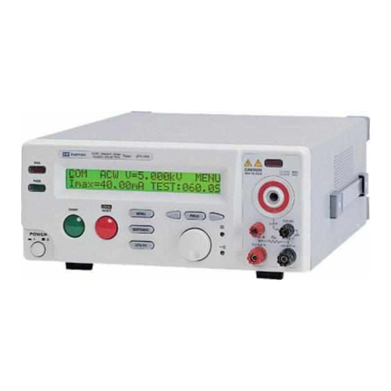
Electrical Safety Tester
GPT/GPI-700A Series
USER MANUAL
GW INSTEK PART NO. 82PI-74500MG1
ISO-9001 CERTIFIED MANUFACTURER
This manual contains proprietary information, which is protected
by copyrights. All rights are reserved. No part of this manual may
be photocopied, reproduced or translated to another language
without prior written consent of Good Will company.
The information in this manual was correct at the time of printing.
However, Good Will continues to improve products and reserves
the rights to change specification, equipment, and maintenance
procedures at any time without notice.
Good Will Instrument Co., Ltd.
No. 7-1, Jhongsing Rd., Tucheng City, Taipei County 236, Taiwan.
Advertisement
Table of Contents


Need help?
Do you have a question about the GPT-700A Series and is the answer not in the manual?
Questions and answers