GW Instek GDS-3152 User Manual
Digital storage oscilloscope
gds-3000 series
Hide thumbs
Also See for GDS-3152:
- User manual (209 pages) ,
- User manual (12 pages) ,
- User manual (209 pages)

Related Manuals for GW Instek GDS-3152


Summary of Contents for GW Instek GDS-3152
-
Page 1: Digital Storage Oscilloscope
Digital Storage Oscilloscope GDS-3000 Series USER MANUAL GW INSTEK PART NO. 82DS-33040MA1 ISO-9001 CERTIFIED MANUFACTURER GlobalTestSupply www. .com nd Quality Products Online at: sales@GlobalTestSupply.co... - Page 2 This manual contains proprietary information, which is protected by copyright. All rights are reserved. No part of this manual may be photocopied, reproduced or translated to another language without prior written consent of Good Will company. The information in this manual was correct at the time of printing. However, Good Will continues to improve products and reserves the rights to change specification, equipment, and maintenance procedures at any time without notice.
-
Page 3: Table Of Contents
TABLE OF CONTENTS Table of Contents SAFETY INSTRUCTIONS ..........5 GETTING STARTED ............10 GDS-3000 Series Overview ....11 Appearance .......... 17 Set Up ..........28 QUICK REFERENCE ............36 Menu Tree / Operation Shortcuts ..38 Default Settings ........52 Built-in Help ........ - Page 4 GDS-3000 Series User Manual Create/Edit file labels ......151 Save ........... 153 Recall ..........160 Reference Waveforms ......165 FILE UTILITIES ............. 167 PRINT OUT ..............174 REMOTE CONTROL CONFIG ........177 Interface Configuration ...... 178 Web Server ......... 184 MAINTENANCE ............
-
Page 5: Safety Instructions
SAFETY INSTRUCTIONS AFETY INSTRUCTIONS This chapter contains important safety instructions that you must follow during operation and storage. Read the following before any operation to insure your safety and to keep the instrument in the best possible condition. Safety Symbols These safety symbols may appear in this manual or on the GDS- 3000. -
Page 6: Safety Guidelines
GDS-3000 Series User Manual Do not dispose electronic equipment as unsorted municipal waste. Please use a separate collection facility or contact the supplier from which this instrument was purchased. Safety Guidelines Make sure the BNC input voltage does not General ... - Page 7 SAFETY INSTRUCTIONS AC Input voltage: 100 ~ 240V AC, 48 ~ 63Hz, Power Supply auto selection. Power consumption: 96VA. WARNING Connect the protective grounding conductor of the AC power cord to an earth ground, to avoid electrical shock. Disconnect the power cord before cleaning.
- Page 8 GDS-3000 Series User Manual Do not dispose this instrument as unsorted Disposal municipal waste. Please use a separate collection facility or contact the supplier from which this instrument was purchased. Please make sure discarded electrical waste is properly recycled to reduce environmental impact.
- Page 9 SAFETY INSTRUCTIONS Power cord for the United Kingdom When using the oscilloscope in the United Kingdom, make sure the power cord meets the following safety instructions. NOTE: This lead/appliance must only be wired by competent persons WARNING: THIS APPLIANCE MUST BE EARTHED IMPORTANT: The wires in this lead are coloured in accordance with the following code: Green/ Yellow:...
- Page 10 GDS-3000 Series User Manual ETTING STARTED This chapter describes the GDS-3000 in a nutshell, including its main features and front / rear panel introduction. After going through the overview, follow the Set Up section to properly set up the oscilloscope for first-time use. The Set Up section also includes a starter on how to use this manual effectively.
-
Page 11: Getting Started
GETTING STARTED GDS-3000 Series Overview Series lineup The GDS-3000 series consists of 8 models, divided into 2-channel and 4-channel versions. Model name Frequency Input channels Real-time bandwidth Sampling Rate GDS-3152 150MHz 2.5GSa/s GDS-3252 250MHz 2.5GSa/s GDS-3352 350MHz 5GSa/s GDS-3502 500MHz... -
Page 12: Main Features
GDS-3000 Series User Manual The 2 channel and 4 channel models differ in the position of the horizontal controls, the math, reference and bus keys as well as the position of the EXT trigger. 2-Channel models 4-Channel models HORIZONTAL TRIGGER VARIABLE TRIGGER VARIABLE... -
Page 13: Accessories
GETTING STARTED Three standard input impedances (50Ω/75Ω/1MΩ) Optional power measurement functions are available for fast analysis of power quality tests Optional analysis software for I C, SPI and UART serial signal triggering and decoding 2 and 4 channel models available up to 500 MHz ... - Page 14 GDS-3000 Series User Manual GPIB to USB adapter GPIB Interface Optional Part number Description Accessories Instrument cart, 470(W)x430(D)mm GTC-001 (U.S. type input socket) Instrument cart, 330(W)x430(D)mm GTC-002 (U.S. type input socket) test lead, BNC to BNC heads GTL-110 RS-232C cable, 9-pin Female to 9-pin GTL-232 female, Null modem for computer USB cable, USB2.0A-B type cable 4P...
- Page 15 GETTING STARTED Passive probe; 350 MHz, 10X with GTP-351R readout Passive probe, 500MHz, 10X with GTP-501R readout Drivers USB driver LabVIEW driver GlobalTestSupply www. .com nd Quality Products Online at: sales@GlobalTestSupply.co...
-
Page 16: Package Contents
Check the contents before using the GDS-3000. Opening the Box Main unit Contents Probe set GTP-151R for GDS-3152 / GDS-3154 GTP-251R for GDS-3252 / GDS-3254 GTP-351R for GDS-3352 / GDS-3354 GTP-501R for GDS-3502 / GDS-3504 Power cord User manual (this document) ... -
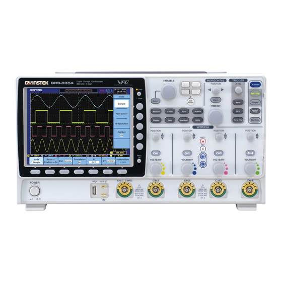
Page 17: Appearance
GETTING STARTED Appearance GDS-3504/3354/3254/3154 Front Panel Split window Variable knob Function Horizontal cluster and select key keys controls HORIZONTAL TRIGGER VARIABLE GDS-3354 Digital Storage Oscilloscope Trigger 350 MHz 5 GS/s POSITION LEVEL Autoset Visual Persistence Oscilloscope Print Print key Print/Save key Run/Stop controls Save... - Page 18 GDS-3000 Series User Manual 8” SVGA TFT color LCD. 800 x 600 resolution, LCD Display wide angle view display. Use the Menu Off key to hide the Menu Key onscreen menu system. The Side menu and Bottom menu keys are used to Side Menu Keys make selections from the soft-menus on the LCD user interface.
- Page 19 GETTING STARTED Use the Split Window key to cycle Split Window between single and split screen Cluster mode. For more details on windowing, see page 66. The horizontal controls are used to change the Horizontal Controls position of the cursor, set the time base settings, and to zoom into the waveforms.
- Page 20 GDS-3000 Series User Manual Press the Autoset key to Autoset automatically set the trigger, horizontal scale and vertical scale. Press to freeze (Stop) or continue Run/Stop Key (Run) signal acquisition (page59). Sets the acquisition mode to single Single triggering mode. Resets the oscilloscope to default Default Setup settings.
- Page 21 GDS-3000. Configures and runs automatic Measure measurements. Configures and runs cursor Cursor measurements. Configures and runs GW Instek Test Test applications and optional functions such as the Power Analysis measurement software. Configures the Acquisition mode. Acquire Configures the display settings.
- Page 22 GDS-3000 Series User Manual TypeA, 1.1/2.0 compatible. Used USB Host Port for data transfer. Accepts the DUT ground lead for Ground Terminal common ground. Outputs 2Vp-p, square wave Probe Compensation signal for probe compensation Output (page 190). Accepts external trigger signals External Trigger (page 125).
-
Page 23: Rear Panel
GETTING STARTED Rear Panel Trigger Go/No Go Video RS232C Line output output Output Port Ground strap connector Calibration output Device/ Host port Key lock Power input Rear socket stand Outputs the signal for vertical scale Calibration accuracy calibration (page 187). Output Outputs the trigger timing. - Page 24 GDS-3000 Series User Manual Ethernet port. LAN Port For use with a grounding strap. Ground Strap Connector The USB device port is used for USB Device Port remote control and for the FreeWave remote control software. USB 1.1/2.0 high speed compatible. The USB host port supports USB USB Host flash drives for external memory.
-
Page 25: Display
GETTING STARTED Display Acquistion mode Memory bar Trigger Date and Trigger status time position Trigger Waveform Channel level indicator Horizontal Signal Channel status status frequency Automatic measurements Trigger configuration Shows input signal waveforms. Waveforms Channel 1: Yellow Channel 2: Blue Channel 3: Pink Channel 4: Green Channel Indicator The channel indicator shows the zero volt level of... - Page 26 GDS-3000 Series User Manual Current date and time (page 144). Date and Time Memory Bar The ratio and the position of the displayed waveform compared with the internal memory (page 112). Triggered. Trigger Status Not triggered, display not updated. Trigger stopped. Also appears in Run/Stop (page59).
- Page 27 GETTING STARTED Trigger source, slope, Trigger voltage, coupling. Configuration Trigger source, trigger (video), field, line, coupling. For trigger details, see page 125. Channel 1, inverted, AC Channel Status coupling, 1V/Div Channel 1, GND coupling, 1V/Div For channel details, see page 117. GlobalTestSupply www.
-
Page 28: Set Up
GDS-3000 Series User Manual Set Up Tilt Stand Turn the legs under the casing as shown below to Upright have the instrument sit upright. To tilt, tilt the legs back behind the casing, as Tilt shown below. GlobalTestSupply www. .com nd Quality Products Online at: sales@GlobalTestSupply.co... -
Page 29: Power Up
GETTING STARTED Power Up 1. Connect the power cord to Step the rear panel socket. 2. Press the POWER key. The display becomes active in ~ 30 seconds. : ON : OFF The GDS-3000 recovers the state right before the Note power is turned OFF. -
Page 30: First Time Use
GDS-3000 Series User Manual First Time Use This section describes how to connect a signal, Background adjust the scale, and compensate the probe. Before operating the GDS-3000 in a new environment, run these steps to make sure the instrument performs at its full potential. Follow the procedures on the previous page. - Page 31 GETTING STARTED Press the Autoset key. A square 6. Capture Signal Autoset waveform appears on the center of (Autoset) the screen. For Autoset details, see page 58. Press the Display key, and set the 7. Select Vector Display display to Vector on the bottom menu. Waveform Turn the adjustment point on the probe to make 8.
-
Page 32: How To Use This Manual
GDS-3000 Series User Manual 9. Start Operation Continue with the other operations. Measurement: page 55 Configuration: page 87 Save/Recall page 146 File Utilities page 166 Remote Control Print Out 174 page 177 How to Use This Manual This section describes the conventions used in this Background manual to operate the GDS-3000. - Page 33 GETTING STARTED When the user manual says to “select” a value Selecting a Menu from one of the side menu parameters, first press Item or Parameter the corresponding menu key and use the variable knob to either scroll through a parameter list or to increase or decrease a variable.
- Page 34 GDS-3000 Series User Manual Toggling a Menu Parameter 1. Press the bottom menu key to toggle the parameter. Reduce Lower Menu GlobalTestSupply www. .com nd Quality Products Online at: sales@GlobalTestSupply.co...
- Page 35 GETTING STARTED 1. Press the relevant function key again to reduce the bottom menu. For example: press the trigger menu key to reduce the trigger menu. Remove All Menus 1. Press the Menu Off key to reduce each menu level. GlobalTestSupply www.
-
Page 36: Quick Reference
GDS-3000 Series User Manual UICK REFERENCE This chapter describes the GDS-3000 menu tree, shortcuts to major operations, built-in Help access, and default factory settings. Use them as a handy reference to get a quick access to the functionality. Menu Tree / Operation Shortcuts ........38 Convention ................ - Page 37 QUICK REFERENCE Default Settings ............. 52 Built-in Help ..............54 GlobalTestSupply www. .com nd Quality Products Online at: sales@GlobalTestSupply.co...
-
Page 38: Menu Tree / Operation Shortcuts
GDS-3000 Series User Manual Menu Tree / Operation Shortcuts Convention For all menu trees, bottom menu keys are shown as grey icons and side menu keys are shown in white. All menu tree operations are shown in order from top to bottom. Below is an example of the menu tree operation for the trigger source menu and a comparison to the operation on the DSO screen. -
Page 39: Acquire Key
QUICK REFERENCE Acquire Key Sets the acquisition mode. Acquire Reset H Sample rate Mode Position to 0s XXXMSPS Sample OFF'YT( Peak Detect Sin(x)/x Triggered Hi Resolution Average 2,4,8,16,32,64, 128,256 Autoset Key Automatically finds the signal and sets the horizontal and vertical scale. -
Page 40: Auto-Range
GDS-3000 Series User Manual Auto-Range Constantly adjusts the vertical and or horizontal scale. Auto-Range Vertical Vertical Undo Horizontal Autoranging Mode Only Autoranging Only Horizontal Fit Screen AC Priority CH1 ~ 4 Key Set the channel input parameters. Position/ Set to 0 Coupling Impedence Invert... -
Page 41: Cursor Key
QUICK REFERENCE Cursor Key Set cursor positions. Cursor H Cursor V Cursor Display Key Set the display properties. Display Dot Vector Persistence Intensity Waveform Graticule Time Gray Full Waveform Intensity Vector 0%~100% Color Grid Auto Cross Hair 100ms~10s Graticule Intensity Frame 10%~100% Infinite... -
Page 42: Math Key
GDS-3000 Series User Manual Math Key Standard math and FFT functions. Math Source 1 Source CH1~CH4 CH1~CH4 Ref1~Ref4 Ref1~Ref4 Operator Vertical Units dBV RMS Linear RMS × Window ÷ Hanning Rectangular Source 2 Hamming CH1~CH4 Ref1~Ref4 Blackman Position Position XXDiv XXDiv Unit/Div Unit/Div... -
Page 43: Measure Key
QUICK REFERENCE Measure Key Display automatic measurements either individually or as voltage/current, time or delay measurement groups. Measure Remove Gating Display All Measurement Measurement Window 1 (Full Record) Window 2 Pk-Pk Window 3 Screen Window 4 Remove All Between Amplitude Cursors High Average... -
Page 44: Print/Save Key
GDS-3000 Series User Manual Print/Save Key Print or save screen images. Print Save Run/Stop Key Freeze/unfreeze signal acquisition Run/Stop REF Key R1ON/OFF R2ON/OFF R3ON/OFF R4ON/OFF Vertical Vertical Vertical Vertical Vertical scale Vertical scale Vertical scale Vertical scale Vertical position Vertical position Vertical position Vertical position Horizontal... -
Page 45: Save/Recall Key
QUICK REFERENCE Save/Recall Key Save and recall images, waveforms and panel setups. Edit labels for reference and setup files. Save/Recall Recall Edit File Recall Save Image Save Waveform Save Setup Setup Waveform Label File Format From Label For From Edit Label Edit Label CH1~CH4 Wave1~20... -
Page 46: Test Key
GDS-3000 Series User Manual Test Key Use the Go-NoGo application as well as additional optional software such as the Power Analysis software. Test APP. Power Analysis Goes to the Power Quality Go-NoGo Power Quality menu Goes to the Harmonics menu Unistall Harmonics Ripple... -
Page 47: Trigger Type Menu
QUICK REFERENCE Trigger Type Menu Menu Type Edge Delay Pulse Width Video Others Pulse Runt Rise & Fall Trigger Edge Menu Type Source Coupling Slope Level Mode Holdoff Edge Auto 10.0ns~ CH1~ CH4 -XX~XXV Normal 10.0s Set to TTL Set to AC Line Reject 1.4V... -
Page 48: Trigger Pulse Width Menu
GDS-3000 Series User Manual Trigger Pulse Width Menu Type Source Polarity When Threshold Mode Holdof Pulse Width CH1~ CH4 > Auto -XX~XXV 10.0ns ~ 10.0s Normal < Set to TTL Set to AC Line ≠ EXT Probe 1.4V Minimum EXT Probe Set to ECL Volt >... -
Page 49: Trigger Pulse Runt Menu
QUICK REFERENCE Trigger Pulse Runt Menu Type Source Polarity When Threshold Mode Holdof Pulse Runt Auto Input > 10.0ns~10.0s -XX~XXV Normal < Set to ≠ -XX~XXV Minimum Set to TTL > 4.00ns~10.0s EXT Probe 1.4V Set to ECL Volt Current -1.3V Alternate Trigger Rise &... -
Page 50: Utility Key
GDS-3000 Series User Manual Utility Key Utility Date & File Utilities Language System Printout Time System USB Device Year Function English Create Folder Info 2XXX Print Port Trad. Chinese Save Simp. Chinese Month Day More 1 of 2 Rename Ethernet Jan~Dec Ink Saver Korean... -
Page 51: Utility Key - File Utilities
QUICK REFERENCE Utility Key – File Utilities File Utilities Create Folder Delete Copy To USB Rename Keypad Keypad Enter Character Enter Character Back Space Back Space Editing Editing Completed Completed Cancel Cancel Zoom Key Zoom Reset Zoom Reset H Position Position to 0s to 0s Fine Coarse... -
Page 52: Default Settings
GDS-3000 Series User Manual Default Settings Default The default factory installed settings can be Setup recalled at any time by pressing the Default Setup key. Mode: Sample XY: OFF Acquire Interpolation: Sin(x)/x Sample rate: 250MSPS (200MSPS GDS350X) Mode: Vector Persistence: Auto Display Waveform intensity: 50% Graticule intensity: 50% Waveform visuals: Gray Graticule: full... - Page 53 QUICK REFERENCE Slope: positive Level: 0.00V Mode: Auto Holdoff: 10.0ns Print key: Save Ink Saver: Off Utility Image file format: Bmp Data file format: LSF Save Recall GlobalTestSupply www. .com nd Quality Products Online at: sales@GlobalTestSupply.co...
-
Page 54: Built-In Help
GDS-3000 Series User Manual Built-in Help The Help key accesses a context sensitive help menu. The help menu contains information on how to use the front panel keys. Panel Operation 1. Press the Help key. The Help display changes to Help mode. -
Page 55: Measurement
MEASUREMENT EASUREMENT Basic Measurement ............57 Channel Activation..............57 Autoset ..................58 Auto-Range................60 Run/Stop .................62 Horizontal Position/Scale ............63 Vertical Position/Scale ............65 Split Window Mode ...............66 Automatic Measurement ............68 Measurement Items ..............68 Individual Mode ..............71 Remove Measurement ............72 Gated mode ................73 Display All mode ..............74 Cursor Measurement ............ - Page 56 GDS-3000 Series User Manual Serial Bus Overview .............. 96 GlobalTestSupply www. .com nd Quality Products Online at: sales@GlobalTestSupply.co...
-
Page 57: Basic Measurement
MEASUREMENT Basic Measurement This section describes the basic operations required in capturing and viewing the input signal. For more detailed operations, see the following chapters. Cursor Measurement → from page 76 Configuration → from page 87 Before operating the oscilloscope, please see the Getting Started chapter, page 10. -
Page 58: Autoset
GDS-3000 Series User Manual To activate the default state, Default Setup Default press Default Setup. Setup The Autoset key (page 58) does NOT automatically Autoset activate the channels to which input signals are connected. Autoset The Autoset function automatically configures the Background panel settings to position the input signal to the best viewing condition. - Page 59 MEASUREMENT Before After 3. To undo Autoset, press Undo Autoset from the bottom menu. To remove the Undo Autoset softkey, press any other key. 1. Choose between Fit Screen Mode Change modes and AC Priority Mode from the bottom menu. 2.
-
Page 60: Auto-Range
GDS-3000 Series User Manual Auto-Range The Auto-Range function works similarly to the Background Autoset function, except the Auto-Range function works continuously when it is on. The Auto-Range function will continuously monitor the input signal and adjust the horizontal and vertical scale of a displayed signal so that waveform(s) are displayed at the best possible scale. - Page 61 MEASUREMENT 3. To undo Auto-Range, press Undo Autoranging from the bottom menu. Press Autoranging from the bottom Disable Auto- menu to turn Auto-Range On/Off. Range Press Vertical Only for vertical Configure Auto- autoranging only. Range Press Horizontal Only for horizontal autoranging only.
-
Page 62: Run/Stop
GDS-3000 Series User Manual Run/Stop By default, the waveform on the display is Background constantly updated (Run mode). Freezing the waveform by stopping signal acquisition (Stop mode) allows flexible observation and analysis. To enter Stop mode, two methods are available: pressing the Run/Stop key or using the Single Trigger mode. -
Page 63: Horizontal Position/Scale
MEASUREMENT Horizontal Position/Scale For more detailed configuration, see page 112. The horizontal position knob Set Horizontal moves the waveform left and Position right. As the waveform moves, the memory bar on the top of the display indicates the portion of the waveform currently shown on the display and the position of the horizontal marker on the waveform. - Page 64 GDS-3000 Series User Manual The Time/Division rate is displayed to the left of the H icon at the bottom of the screen. Memory bar The size of the memory bar changes to reflect the timebase and the section of the waveform that is displayed on screen.
-
Page 65: Vertical Position/Scale
MEASUREMENT Vertical Position/Scale For more detailed configuration, see page117. To move the waveform up or Set Vertical POSITION down, turn the vertical position Position knob for each channel. Down As the waveform moves, the vertical position of the cursor appears on the display. The waveform can be moved Run/Stop vertically in both Run and Stop... -
Page 66: Split Window Mode
GDS-3000 Series User Manual Split Window Mode The split window mode is able to display and trigger each active channel independently. The split window mode is especially useful for signal comparisons. Reference waveforms can also be used in this mode. Most functions and features can be used with split screen mode except for the Math, XY display and Zoom mode. - Page 67 MEASUREMENT To select the active channel, press the Select Active corresponding split window key: Channel 4 Window split screen: 2 window split screen: Window Window Window Window Window Window Window Window Reference waveforms can also be used in this Reference mode.
-
Page 68: Automatic Measurement
GDS-3000 Series User Manual Automatic Measurement The automatic measurement function measures and updates major items for Voltage/Current, Time, and Delay type measurements. Measurement Items V/I Measurements Time Meas. Delay Meas. Overview Pk-Pk Frequency Period RiseTime FallTime Amplitude +Width High -Width Dutycycle Average Phase... - Page 69 MEASUREMENT Global high voltage High Global low voltage Averaged voltage of the first Average cycle RMS (root mean square) voltage Rise overshoot voltage ROVShoot Fall overshoot voltage FOVShoot Rise preshoot voltage RPREShoot Fall preshoot voltage FPREShoot Frequency of the waveform Time Frequency Measurement...
- Page 70 GDS-3000 Series User Manual Time between: Delay Source 1 first rising edge and Measurement Source 2 first rising edge Time between: Source 1 first rising edge and Source 2 first falling edge Time between: Source 1 first falling edge and Source 2 first rising edge Time between: Source 1 first falling edge and...
-
Page 71: Individual Mode
MEASUREMENT Individual Mode Individual mode shows up to eight selected measurement items on bottom of the screen from any channel source. 1. Press the Measure key. Measure Measurement Item 2. Press Add Measurement from the bottom menu. 3. Choose either a V/I, Time or Delay measurement from the side menu. -
Page 72: Remove Measurement
GDS-3000 Series User Manual Choose a Source The channel source for measurement items can be set either before or when selecting a measurement item. 1. To set the source, press either the Source1 or Source2 key from the side menu and choose the source. Source 2 is only for delay measurements. -
Page 73: Gated Mode
MEASUREMENT Remove All Items Press Remove All to remove all the measurement items in full screen mode, or to remove all the measurement items for the active window in split screen mode. Gated mode Some automatic measurements can be limited to a “gated” area between cursors. -
Page 74: Display All Mode
GDS-3000 Series User Manual Display All mode Display All mode shows and updates all items from Voltage and Time type measurements. 1. Press the Measure key. View Measure Measurement Results 2. Press Display All from the bottom menu. 3. Choose a channel (CH1, CH2, CH3, CH4) from the side menu to display auto measurement items. - Page 75 MEASUREMENT Delay type measurement is not available in this Delay mode as only one channel is used as the source. Measurements Use the Individual measurement mode (page 71) instead. GlobalTestSupply www. .com nd Quality Products Online at: sales@GlobalTestSupply.co...
-
Page 76: Cursor Measurement
GDS-3000 Series User Manual Cursor Measurement Horizontal or vertical cursors are used to show the position and values of waveform measurements and math operation results. These results cover voltage, time, frequency and other math operations. When the cursors (horizontal, vertical or both) are activated, they will be shown on the main display unless turned off. - Page 77 MEASUREMENT 5. Use the Variable knob to move the Left Right movable cursor(s) left or right. VARIABLE Example Horizontal cursors FFT Math has different content. FFT Math For FFT math details, see page Frequency, dB/V Cursor Frequency, dB/V Cursor Delta (difference between cursors) Example Horizontal cursors...
- Page 78 GDS-3000 Series User Manual XY mode cursors measure a number of X by Y XY Mode measurements. Time, rectangular, polar co-ordinates, product, ratio. Cursor Time, rectangular, polar co-ordinates, product, ratio. Cursor Delta (difference between cursors) Example Horizontal cursors GlobalTestSupply www. .com nd Quality Products Online at: sales@GlobalTestSupply.co...
-
Page 79: Use Vertical Cursors
MEASUREMENT Use Vertical Cursors 1. Press the Cursor key twice. Panel Operation/ Cursor Range 2. Press V Cursor from the bottom menu. 3. Press V Cursor repeatedly to toggle the cursor type. Range Upper cursor movable, lower cursor position fixed Lower cursor movable, upper cursor position fixed Upper and lower cursor movable... - Page 80 GDS-3000 Series User Manual Example Horizontal cursors Vertical cursors The FFT Math has different FFT Math content. For FFT math details, see page 85. Frequency/Time: cursor1, cursor2 dB/V: cursor1, cursor2 Delta (difference between cursors) Example Horizontal cursors Vertical cursors GlobalTestSupply www.
- Page 81 MEASUREMENT XY mode cursors measure a number of X by Y XY Mode measurements. Rectangular, polar co-ordinates, product, ratio. Cursor Rectangular, polar co-ordinates, product, ratio. Cursor Delta (difference between cursors) Example Vertical cursors Horizontal cursors GlobalTestSupply www. .com nd Quality Products Online at: sales@GlobalTestSupply.co...
-
Page 82: Math Operation
GDS-3000 Series User Manual Math Operation Overview Math operation runs addition, subtraction, Background multiplication, division or FFT using the input signals or reference waveforms (Ref1~4) and shows the result on the display. The resulted waveform characteristics can be measured using the cursors. -
Page 83: Addition/Subtraction/Multiplication/Division
MEASUREMENT Frequency resolution Good Hamming FFT Window Amplitude resolution Not good Frequency measurement on Suitable for..periodic waveforms Frequency resolution Very good Rectangular FFT Window Amplitude resolution Bad Single-shot phenomenon Suitable for..(this mode is the same as having no window at all) Frequency resolution Bad Blackman FFT Window... - Page 84 GDS-3000 Series User Manual 5. Select Source 2 from the side menu. CH1~4, Ref~4 Range 6. The math measurement result appears on the display. The vertical scale of the math waveform appears at the bottom of the screen. From left: Math function, source1, operator, source2, Unit/div Example Source 1...
-
Page 85: Fft
MEASUREMENT Panel Operation 1. Press the Math key. 2. Press FFT from the bottom menu. 3. Select the Source from the side menu. CH1~4, Ref~4 Range 4. Press the Vertical Units key from the side menu to select the vertical units used. - Page 86 GDS-3000 Series User Manual Source Math Position and Unit To move the FFT waveform vertically, press Position and use the variable knob. –12.00 Div ~ +12.00 Div Range To select the vertical scale of FFT waveform, press Unit/div and use the variable knob.
-
Page 87: Applications
MEASUREMENT Applications Overview The APP. function allows different applications to Background be run. Applications can be downloaded from the GW Instek website. The GO_NOGO application can be Included GO-NOGO used to set threshold boundaries Applications for input signals. GO-NOGO checks if a waveform fits inside a... -
Page 88: Uninstalling Applications
GDS-3000 Series User Manual 3. Scroll through each Application using the Variable knob. 4. Select an application by pressing Select the Select key twice. ×2 Uninstalling Applications Any APP. function can be easily uninstalled using Background the Uninstall function. Panel Operation 1. Press the Test key. Test 2. - Page 89 MEASUREMENT 3. Scroll through each Application using the Variable knob. 4. When the desired application is highlighted, press Uninstall to begin the uninstallation. Press ×2 again to confirm. GlobalTestSupply www. .com nd Quality Products Online at: sales@GlobalTestSupply.co...
-
Page 90: Using Go_Nogo
GDS-3000 Series User Manual Using Go_NoGo The Go-NoGo test checks if a waveform fits inside Background a user-specified maximum and minimum boundary (boundary template). Boundary templates are automatically created from a source channel. Boundary tolerance and violation conditions can be set. Choose the Go_NoGo application from the APP. - Page 91 MEASUREMENT Enters: Sets the NoGo condition to when the input signal stays within the limit boundary. 2. Press When again to change the menu to Violating. Use the Variable knob to choose the action for when a violation occurs. Stop: The waveform will be frozen. Violating Stop_Beep: The waveform will be frozen and a beep will be output.
- Page 92 GDS-3000 Series User Manual 1. To set a maximum and minimum Maximum and boundary, press Minimum Position Minimum from the bottom menu and use the Variable knob to select the absolute minimum position. Voltage division range Position 2. Press Minimum Position again to toggle the menu to Maximum Position.
- Page 93 MEASUREMENT Press Enable to start the Go-NoGo test. Start Go-NoGo The Enable button will change to Disable. Pressing Disable will stop the Go-NoGo test and toggle the button back to Enable. To exit the application, press Break. Exit the Application To output the Go-NoGo results to an Using the Go- external device, the Go-NoGo rear...
- Page 94 GDS-3000 Series User Manual Circuit Diagram 220Ω B+ CMOS (Max 16V) Or TTL (Max 5V) Go-NoGo signal Go-NoGo GlobalTestSupply www. .com nd Quality Products Online at: sales@GlobalTestSupply.co...
-
Page 95: Power Analysis
MEASUREMENT Power Analysis Power analysis provides automatic measurement for a number of advanced measurement types such as power quality, harmonics, ripple and inrush current. The Power analysis software is an optional software module, for details please see page 192. Please see the Power Analysis manual for more details on using the power analysis software. -
Page 96: Serial Bus
GDS-3000 Series User Manual Serial Bus The serial bus trigger and decode software includes support for 3 common serial interfaces, SPI (4 channel models only), UART and C. Each interface is fully configurable to accommodate a wide range of protocol variation. Each input can be displayed as binary or hexadecimal. - Page 97 MEASUREMENT SCLK, SDA Threshold Configuration Addressing mode, Read/Write in address Start, Repeat Start, Stop, Missing Trigger On Ack, Address, Data, Address/Data The SPI (Serial Interface Peripheral) bus is fully configurable to accommodate the wide variety of SPI interfaces. This bus is only available on 4 channel models.
-
Page 98: Configuration
GDS-3000 Series User Manual ONFIGURATION Acquisition ..............100 Select Acquisition Mode ............. 100 Show Waveform in XY Mode........... 102 Set the Sampling Mode ............104 Real time vs Equivalent Time Sampling Mode ....105 Display ................. 106 Display Waveform as Dots or Vectors ......106 Set the Level of Persistence .......... - Page 99 CONFIGURATION Trigger ................125 Trigger Type Overview ............125 Trigger Parameter Overview ..........127 Setup Holdoff Level ............131 Setup Trigger Mode ............132 Using the Edge Trigger ............132 Using Advanced Delay Trigger ......... 134 Using Pulse Width Trigger..........135 Using Video Trigger ............
-
Page 100: Acquisition
GDS-3000 Series User Manual Acquisition The Acquisition process samples the analog input signals and converts them into digital format for internal processing. Select Acquisition Mode The acquisition mode determines how the samples Background are used to reconstruct a waveform. This is the default acquisition Sample mode. - Page 101 CONFIGURATION 2. To set the Acquisition mode, press Mode on the bottom menu. 3. Select an acquisition mode from the side menu. Mode Sample, Peak Detect, Hi Resolution, Average Average 2, 4, 8, 16, 32, 64, 128, sample Example Sample Peak Detect High Resolution Average (256 times)
-
Page 102: Show Waveform In Xy Mode
GDS-3000 Series User Manual Show Waveform in XY Mode The XY mode maps the voltage of channel 1 to the Background voltage of channel 2. In 4 channel models, the voltage of channel 3 is mapped to the voltage of channel 4. - Page 103 CONFIGURATION X-Y mode is split into two windows. The top window shows the signals over the full time range. The bottom window shows XY mode. POSITION To move the X Y waveform position, use the vertical position knob: Channel 1 knob moves the X Y Down waveform horizontally, Channel 2 knob moves the X Y waveform...
-
Page 104: Set The Sampling Mode
GDS-3000 Series User Manual Set the Sampling Mode The GDS-3000 has two types of sampling modes: Background ET (Equivalent Time) and Sin(x)/x interpolation. Equivalent time sampling is able to achieve a sample rate of 100GSa/s when sampling periodic waveforms. Sin(x)/x interpolation uses a sinc interpolation formula to reconstruct a continuous signal between sampled points. -
Page 105: Real Time Vs Equivalent Time Sampling Mode
CONFIGURATION Real Time vs Equivalent Time Sampling Mode The sampling mode on the GDS-3000 can be Background switched between two sampling modes: Real-time and Equivalent-time. The number of active channels in operation will determine the sampling rate of the DSO. The sampling rate and mode depends on the number of active channels and whether the oscilloscope model has 2 or 4 channels. -
Page 106: Display
GDS-3000 Series User Manual Display The Display menu defines how the waveforms and parameters appear on the main LCD display. Display Waveform as Dots or Vectors When the waveform is displayed on screen, it can Background be displayed as dots or vectors. Panel Operation 1. -
Page 107: Set The Level Of Persistence
CONFIGURATION Set the Level of Persistence The persistence function allows the GDS-3000 to Background mimic the trace of a traditional analog oscilloscope. A waveform trace can be configured to “persist” for designated amount of time. Panel Operation 1. Press the Display menu key. Display 2. - Page 108 GDS-3000 Series User Manual 3. To set the waveform intensity, press Waveform Waveform Intensity and edit the intensity. Intensity 0~100% Range 4. To set the graticule intensity, press Graticule Graticule Intensity from the side menu and edit the Intensity intensity value. 10~100% Range Example...
-
Page 109: Set The Waveform Intensity Type
CONFIGURATION Set the Waveform Intensity Type The intensity gradient of a signal can be set to Background grayscale or color. If intensity is set to color, the intensity gradient is analogous to a thermal color gradient where high intensity areas are colored red and low intensity areas are colored blue. -
Page 110: Select Display Graticule
GDS-3000 Series User Manual Select Display Graticule Panel Operation 1. Press the Display menu key. Display 2. Press Graticule from the bottom menu. 3. From the side menu choose the graticule display type. Full : Shows the full grid; X and Y axis for each division. -
Page 111: Freeze The Waveform (Run/Stop)
CONFIGURATION Freeze the Waveform (Run/Stop) For more details about Run/Stop mode, see page 59. Panel Operation 1. Press the Run/Stop key. To Run/Stop unfreeze the waveform, press the Run/Stop key again. 2. The waveform and the trigger freezes. The trigger indicator on the top right of the display shows Stop. -
Page 112: Horizontal View
GDS-3000 Series User Manual Horizontal View This section describes how to set the horizontal scale, position, and waveform display mode. Move Waveform Position Horizontally Panel Operation The horizontal position knob moves the waveform left/right. As the waveform moves, a position indicator on the on the top of the display indicates the horizontal position of the waveform in memory. -
Page 113: Select Horizontal Scale
CONFIGURATION Select Horizontal Scale TIME/DIV Down To select the timebase (scale), turn the Select Horizontal TIME/DIV knob; left (slow) or right Scale (fast). Range 1ns/div ~ 100s/div, 1-2-5 increment (1-2.5-5 for GDS-350X) The timebase indicator updates as the TIME/DIV is adjusted. Horizontal position Time base... -
Page 114: Select Waveform Update Mode
GDS-3000 Series User Manual Select Waveform Update Mode The display update mode is switched Background automatically or manually according to the timebase and trigger. Updates the whole displayed waveform at Normal once. Automatically selected when the timebase (sampling rate) is fast. ≤50ms/div (≥50kSa/s) Timebase all modes... -
Page 115: Zoom Waveform Horizontally
CONFIGURATION Zoom Waveform Horizontally When in Zoom mode the screen is split into 2 Background sections. The top of the display shows the full record length, with the bottom of the screen showing the normal view. Panel Operation 1. Press the Zoom key. Zoom 2. - Page 116 GDS-3000 Series User Manual The zoom time base (Z) at the bottom of the screen will change accordingly. Use the Variable knob to pan the zoom Move the Zoom Left Right window horizontally. Window VARIABLE To reset the Zoom position, press Reset Zoom Position to 0s.
-
Page 117: Vertical View (Channel)
CONFIGURATION Vertical View (Channel) This section describes how to set the vertical scale, position, and coupling mode. Move Waveform Position Vertically POSITION Panel Operation 1. To move the waveform up or down, turn the vertical position knob for each channel. Down 2. -
Page 118: Select Coupling Mode
GDS-3000 Series User Manual The vertical scale indicator on the bottom left of the display changes accordingly for the specific channel. 2mV/div ~ 1V/div (50Ω/75Ω), Range 2mV/div ~ 5V/div (1MΩ). 1-2-5 increments In Stop mode, the vertical scale setting can be Stop Mode changed. -
Page 119: Set The Impedance
CONFIGURATION Example Observing the AC portion of the waveform using AC coupling DC coupling AC coupling Set the Impedance Panel Operation 1. Press the Channel key. 2. Press Impedance repeatedly to toggle between the impedance settings. 1MΩ, 75Ω, 50Ω Impedance Invert Waveform Vertically Panel Operation 1. -
Page 120: Limit Bandwidth
GDS-3000 Series User Manual Limit Bandwidth Bandwidth limitation puts the input signal into a Background selected bandwidth filter. This function is useful for cutting out high frequency noise to see a clear waveform shape. The bandwidth filters available are dependent on the bandwidth of the oscilloscope model. -
Page 121: Expand By Ground/Center
CONFIGURATION Example BW Full BW Limit 20MHz Expand by Ground/Center When the voltage scale is changed, the Expand Background function designates whether the signal expands from the center of the signal or from the signal ground level. Expand by center can be used to easily see if a signal has a voltage bias. -
Page 122: Select Probe Type
GDS-3000 Series User Manual If the vertical scale is changed when the Expand Example function is set to ground, the signal will expand from the ground level*. The ground level does not change when the vertical scale is changed. If the vertical scale is changed when the Expand function is set to center, the signal will expand from the center of the signal. -
Page 123: Select Probe Attenuation Level
CONFIGURATION Select Probe Attenuation Level A signal probe has an attenuation switch to lower Background the original DUT signal level to the oscilloscope input range, if necessary. The probe attenuation selection adjusts the vertical scale so that the voltage level on the display reflects the real value on a DUT. -
Page 124: Set The Deskew
GDS-3000 Series User Manual Set the Deskew The deskew function is used to compensate for the Background propagation delay between the oscilloscope and the probe. Panel Operation 1. Press one of the Channel keys. 2. Press Probe from the bottom menu. 3. -
Page 125: Trigger
CONFIGURATION Trigger The trigger configures the conditions for when the GDS-3000 captures a waveform. Trigger Type Overview The edge trigger is the simplest trigger type. An Edge edge trigger triggers when the signal crosses an amplitude threshold with either a positive or negative slope. - Page 126 GDS-3000 Series User Manual Delay trigger example (by time) Ext. trigger input Source Delay time length First triggering point Triggers when the pulse width of the signal is less Pulse Width than, equal, not equal or greater than a specified pulse width.
-
Page 127: Trigger Parameter Overview
CONFIGURATION Trigger Parameter Overview All the following parameters are common for all the trigger types unless stated otherwise. Channel 1 ~ 4 input signals Trigger Source CH1 ~ 4 External trigger input EXT TRIG signal AC mains signal AC Line Alternate between channel sources for Alternate the trigger source. - Page 128 GDS-3000 Series User Manual DC coupling. Coupling (Edge, Delay) AC coupling. Blocks DC components from the trigger circuits. High frequency filter above 50kHz HF reject Low frequency filter below 50kHz LF reject Reject noise DC coupling with low sensitivity to reject noise.
- Page 129 CONFIGURATION Sets the delay time (10ns ~ 10s) Delay Time between the trigger event and the real (Delay) trigger timing. Sets the number of events (1 ~ 65535) Event passed after the trigger event, until the real trigger timing. Sets the source trigger to the minimum Set to time.
- Page 130 GDS-3000 Series User Manual Selects the trigger point in the video signal. Trigger On (Video) 1 or 2 or all. Field 1~263 for NTSC, 1~313 for Line PAL/SECAM, 1~ 525/625 for EDTV, 1~562/750/1125 for HDTV or all. Sets the upper threshold limit. Threshold (Pulse Runt) Sets the lower threshold limit.
-
Page 131: Setup Holdoff Level
CONFIGURATION Setup Holdoff Level The holdoff function defines the waiting period Background before the GDS-3000 starts triggering again after a trigger point. The holdoff function ensures a stable display if there are a number points in a periodic waveform that can be triggered. Holdoff applies to all the triggering types. -
Page 132: Setup Trigger Mode
GDS-3000 Series User Manual Setup Trigger Mode The trigger mode can be set to Normal or Auto Background (untriggered roll). The triggering mode applies to all the trigger types. See page 114. Panel Operation 1. Press the Trigger menu key. Menu 2. - Page 133 CONFIGURATION 5. Use the side menu to select the trigger source type. Channel 1 ~ 4 (Alternate On/Off), Range Line, EXT (Ext Probe: Volt/Current, Attenuation: 1mX~1kX ), AC Line 6. Press Coupling from the bottom bezel menu to select the trigger coupling or frequency filter settings.
-
Page 134: Using Advanced Delay Trigger
GDS-3000 Series User Manual 12. Set the external trigger level using the side menu. 00.0V~ 5 screen divisions Range Set to TTL 1.4V Set to ECL -1.3V Set to 50% Using Advanced Delay Trigger The EXT trigger source is always used as the delay Background triggering source. -
Page 135: Using Pulse Width Trigger
CONFIGURATION 5. To Delay by Time, press Time from the side menu and set the delay time. 10ns ~ 10s (by time) Range Set to minimum 6. To Delay by Event, press Event from the side menu and set the number of events. - Page 136 GDS-3000 Series User Manual 5. Use the side menu to select the pulse width trigger source. Channel 1 ~ 4 (Alternate On/Off), Range Line, EXT (Ext Probe: Volt/Current, Attenuation: 1mX~1kX ), AC Line 6. Press Polarity to toggle the polarity type.
-
Page 137: Using Video Trigger
CONFIGURATION Using Video Trigger Panel Operation 1. Press the trigger Menu key. Menu 2. Press the Type key from the lower bezel menu. 3. Select Video from the side menu. The video trigger indicator appears at the bottom of the display. From left: channel, video standard, field, line 4. -
Page 138: Pulse Runt Trigger
GDS-3000 Series User Manual 9. Use the side menu to select the field and line. 1, 2, All Field Video line NTSC: 1 ~ 262 (Even), 1 ~ 263 (Odd) PAL/SECAM: 1 ~ 312 (Even), 1 ~ 313 (Odd), EDTV(480P): 1~ 525, EDTV(576P): 1~ 625 HDTV(720P): 1~ 750, HDTV (1080i): 1 ~ 562 (even), 1~563 (odd), HDTV... - Page 139 CONFIGURATION 4. Press Source from the lower menu. 5. Use the side menu to select a source. Channel 1 ~ 4 Range 6. Press Polarity to toggle the polarity. Rising edge, falling edge, either. Range 7. Press When from the lower menu. 8.
-
Page 140: Using Rise And Fall Trigger
GDS-3000 Series User Manual 11. Use the side menu to set the lower threshold. -XXV~XXV Range Set to TTL 1.4V Set to ECL -1.3V Using Rise and Fall Trigger Panel Operation 1. Press the trigger Menu key. Menu 2. Press the Type key from the lower bezel menu. - Page 141 CONFIGURATION 6. Press Slope from the bottom menu to toggle the slope. Rising edge, falling edge, either Range 7. Press When from the lower menu. 8. Then use the side menu to select the logic conditions and true or false status. Condition >...
-
Page 142: System Info / Language / Clock
GDS-3000 Series User Manual System Info / Language / Clock This section describes how to set the interface, beeper, language, time/date, and probe compensation signal. Select Menu Language The following is a list of language available by Parameter default. Language selection may differ according to the region to which the GDS-3000 is shipped. -
Page 143: Erase Memory
CONFIGURATION 2. Press System from the lower menu. 3. Press System Info from the side menu. A display panel will appear showing: Manufacturer name Model name Serial number Firmware version App download Manufacturer URL location Erase Memory The Erase Memory function will erase all internal... -
Page 144: Set The Buzzer Volume
GDS-3000 Series User Manual 2. Press System from the lower menu. 3. Press Erase Memory from the side menu. A message will prompt you to press Erase Memory again to confirm the process. 4. Press Erase Memory. Set the Buzzer Volume Panel Operation 1. - Page 145 CONFIGURATION 2. Press Date & Time on the lower menu. 3. Set the Year, Month, Day, Hour and Minute from the side menu. 2000 ~ 2037 Year 1 ~ 12 Month 1 ~ 31 1~23 Hour 0~59 Minute 4. Press Save Now from the side menu to save the date and time.
-
Page 146: Save/Recall
GDS-3000 Series User Manual AVE/RECALL File Format/Utility ............147 Image File Format ............... 147 Waveform File Format ............147 Spreadsheet File Format ............. 148 Setup File Format ..............149 Create/Edit file labels ............ 151 Save ................153 File Type/Source/Destination .......... 153 Save Image ................ -
Page 147: File Format/Utility
SAVE/RECALL File Format/Utility Image File Format DSxxxx.bmp or DSxxxx.png Format The current display image is 800 by 600 pixels. The Contents background color can be inverted (Ink saver function). Each image file is numbered consecutively from DS0001 to DS9999. Waveform File Format DSxxx.lsf, CH1~CH4.lsf Format The LSF file format efficiently stores waveforms. -
Page 148: Spreadsheet File Format
GDS-3000 Series User Manual Reference waveforms stored in the Ref 1~4 internal memory, separate from W1 ~ W20. Reference waveforms (Ref 1 ~ 4) can be displayed directly onto the display with amplitude and frequency information. Ref 1~4 are useful for reference purposes. -
Page 149: Setup File Format
SAVE/RECALL Horizontal scale Horizontal scale Horizontal position Sampling period Time (of points) Channel Setup File Format DSxxxx.set (proprietary format) Format The setup file saves or recalls the following settings. Mode Contents Acquire Sample rate Sample mode ... - Page 150 GDS-3000 Series User Manual Type Noise Rejection Trigger Source Slope Coupling Level Alternate Mode Rejection Holdoff Language Ink Saver Utility Print key Image file Data file format Save/ ...
-
Page 151: Create/Edit File Labels
SAVE/RECALL Create/Edit file labels Reference files and Setup files stored in internal Format memory can have individual labels set. The labels are used on the reference waveform and setup file icons. Panel Operation 1. Press the Save/Recall key from the Save/Recall front panel. - Page 152 GDS-3000 Series User Manual 2. The Edit Label window appears. 3. Use the Variable knob to highlight a character. VARIABLE Press Enter Character to select a number or letter. Press Back Space to delete a character. Press Editing Completed to create the new label and return to the previous menu.
-
Page 153: Save
SAVE/RECALL Save File Type/Source/Destination Item Source Destination Front panel settings Internal memory: Set1 ~ Panel Setup Set20 (DSxxxx.set) File system: Disk, USB Channel 1 ~ 4 Internal memory: Waveform Data Reference waveform (DSxxxx.csv) Math operation ... -
Page 154: Save Image
GDS-3000 Series User Manual Save Image Panel Operation 1. To save to USB, connect a Front Rear USB drive to the front or Host rear panel USB port. If a USB drive is not connected, images will be saved to the internal memory. -
Page 155: Save Image - Print/Save Key
SAVE/RECALL 6. Press Save Now from the side menu to save the display as an image file. The file will not be saved if the Note power is turned Off or the USB drive is taken out before the message ends. To edit the USB flash drive contents USB File Utility (create/ delete/ rename files and... - Page 156 GDS-3000 Series User Manual 4. On the side menu, press Function repeatedly to select Save. The Save led on the screen bezel Print will be lit when the printout function is set to Save. Save 5. Press the Print/Save key to save to USB.
-
Page 157: Save Waveform
SAVE/RECALL Save Waveform Panel Operation 1. (For saving to an external Front Rear USB flash drive) Connect Host the drive to the front or rear panel USB port. Note: Only one host connection, front or rear, is allowed at a time. 2. -
Page 158: Save Setup
GDS-3000 Series User Manual The file will not be saved if the Note power is turned Off or the USB drive is taken out before the message ends. To edit USB flash drive contents USB File Utility (create/ delete/ rename files and folders), press File Utilities. - Page 159 SAVE/RECALL 4. Press To (internal memory) or To File and choose a destination to save. Set1~Set20 DSxxxx.set To File 5. Press Save Now to confirm saving. When completed, a message appears at the bottom of the display. The file will not be saved if the Note power is turned Off or the USB drive is taken out before the...
-
Page 160: Recall
GDS-3000 Series User Manual Recall File Type/Source/Destination Item Source Destination Factory installed Current front panel Default Panel setting Setup Internal memory: Current front panel Reference Ref1~4 Waveform Internal memory: S1 ~ Current front panel Panel Setup ... - Page 161 SAVE/RECALL Mode: Sample XY: OFF Acquire Sample mode: Sinc Sample rate: 250MSPS (200MSPS GDS350X) Mode: Vector Persistence: Auto Display Waveform intensity: 50% Graticule intensity: 50% Waveform visuals: Gray Graticule: full Scale: 100mV/Div CH1: On Channel Coupling: DC Impedance: 1MΩ Invert: Off Bandwidth: full Expand: By ground Position: 0.00V...
-
Page 162: Recall Waveform
GDS-3000 Series User Manual Language: English Print key: Save Utility Ink Saver: Off Image file format: Bmp Data file format: LSF Save Recall Recall Waveform Panel Operation 1. (For recalling from an Front Rear external USB flash drive) Host Connect the drive to the front or rear panel USB port. -
Page 163: Recall Setup
SAVE/RECALL 6. Press To and select the reference waveform to recall to. Ref1~4 7. Press Recall Now to recall the waveform. To edit USB flash drive contents USB File Utility (create/ delete/ rename files and folders) or to set the file path, press File Utilities. - Page 164 GDS-3000 Series User Manual From File DSxxxx.set (USB, Disk)* * Only files in the current file path will be available. 5. Press Recall Now to confirm recalling. When completed, a message appears at the bottom of the display. The file will not be recalled if the Note power is turned Off or the USB drive is taken out before the...
-
Page 165: Reference Waveforms
SAVE/RECALL Reference Waveforms Recall and Display Reference Waveforms Panel Operation A reference waveform must be stored in advance. See page 155 to store waveforms as reference waveforms. 1. Press the REF key on the front panel. 2. Pressing R1~R4 repeatedly will toggle the corresponding reference waveform OFF/ON. - Page 166 GDS-3000 Series User Manual Press Vertical repeatedly from the side Vertical menu to choose to edit the vertical Navigation position or Volts/Div. Use the Variable knob to edit the values. Press Horizontal repeatedly from the Horizontal side menu to choose to edit the Navigation Time/Div or the horizontal position.
-
Page 167: File Utilities
FILE UTILITIES ILE UTILITIES The file utilities are used each time files need to be saved to internal or external memory. The file utilities can create directories, delete directories and rename files. BMP and PNG image files can be previewed in the file system. The File Utilities menu also sets the file path for saving and recalling files from the Save/Recall menu. - Page 168 GDS-3000 Series User Manual File Navigation The File Utilities menu can be used to choose files or to set the file path for saving/recalling files. File System File path Drive space File cursor File attributes Panel Operation 1. Press the Utility key. Utility 2.
- Page 169 FILE UTILITIES The file path can be set to internal Select memory or to a directory on a USB memory stick. Selecting a waveform file will cause that file to be Note recalled to the currently configured reference waveform. Create Folder Panel Operation 1.
- Page 170 GDS-3000 Series User Manual 5. Use the Variable knob to highlight a character. VARIABLE Press Enter Character to select a number or letter. Press Back Space to delete a character. 6. Press Editing completed to create the folder name. Press Cancel to cancel the operation. Cancel Rename File Panel Operation 1.
- Page 171 FILE UTILITIES Press Rename when a file is chosen. Use the Variable knob to highlight a character. VARIABLE Press Enter Character to select a number or letter. Press Back Space to delete a character. Press Editing completed to create the folder or file name. GlobalTestSupply www.
- Page 172 GDS-3000 Series User Manual Delete File Panel Operation 1. Press the Utility key. Utility Press File Utilities from the bottom menu. Use the variable knob and select key to navigate the file system to choose a file. Press Delete to delete the selected file.
- Page 173 FILE UTILITIES Copy File to USB Panel Operation 1. Connect a USB drive to the Front Rear front or rear panel USB port. Host Note: Only one host connection, front or rear, is allowed at a time. Panel Operation 2. Press the Utility key.
-
Page 174: Print Out
GDS-3000 Series User Manual RINT OUT Screen images can be printed to some PictBridge compatible printers using the USB device port. The GDS-3000 has a dedicated Print/Save key for quick and easy printing. To reduce the amount of printer ink used for each print, images can be printed using the Ink Saver function. - Page 175 PRINT OUT Print Output Ensure the USB port has been configured to Printer before trying to print, see page 174. Panel Operation 1. Press the Utility key. Utility 2. Press Printout from the bottom menu. 3. On the side menu, press Function repeatedly to select Print.
- Page 176 GDS-3000 Series User Manual To have a white background on the Ink Saver saved or printed display image, press Ink Saver repeatedly to toggle Ink Saver On or Off from the side menu. Ink Saver On Ink Saver Off GlobalTestSupply www.
-
Page 177: Remote Control Config
REMOTE CONTROL CONFIG EMOTE CONTROL CONFIG This chapter describes basic configuration for remote control. For a command list, refer to the programming manual downloadable from GWInstek website, www.gwinstek.com Interface Configuration ..........178 Configure USB Interface............ 178 Configure RS-232C Interface ..........179 Configure the Ethernet Interface ........ -
Page 178: Interface Configuration
USB driver included in the FreeWave software package. The driver file automatically sets the GDS-3000 to a serial COM port. The Freewave software package is downloadable from GDS- 3000 product section of the GW Instek website, www.gwinstek.com. GlobalTestSupply www. .com nd Quality Products Online at: sales@GlobalTestSupply.co... -
Page 179: Configure Rs-232C Interface
REMOTE CONTROL CONFIG Configure RS-232C Interface DB-9, Male RS-232C Connector Configuration 2400, 4800, 9600, 19200, 38400, Baud rate 57600, 115200 None, Odd, Even Parity 8 (fixed) Data bit 1, 2 Stop bit Panel Operation 1. Press the Utility key. Utility 2. -
Page 180: Configure The Ethernet Interface
GDS-3000 Series User Manual 7. Press Save Now to save the settings. 8. Connect the RS-232C cable to the rear panel port: DB-9 male connector. For a functionality check, see page 184. 2: RxD (Receive data) Pin Assignment 1 2 3 4 5 3: TxD (Transmit data) 5: GND 6 7 8 9... - Page 181 REMOTE CONTROL CONFIG The Ethernet interface is used for remote control Background over a network. Panel Operation 1. Press the Utility key. Utility 2. Press I/O from the bottom menu. 3. Press Ethernet from the side menu. 4. Set DHCP/BOOTP to On or Off from the side menu.
- Page 182 GDS-3000 Series User Manual 5. Use the Up and Down arrows on the side menu to navigate each Ethernet configuration item. MAC Address, Instrument Name, Items User Password, Instrument IP Address, Domain Name, DNS IP Address, Gateway IP Address, Subnet Mask Note: HTTP Port is fixed at 80.
-
Page 183: Configure Gpib Interface
REMOTE CONTROL CONFIG Configure GPIB Interface To use GPIB, the optional GPIB to USB (GUG-001) adapter must be used. The GPIB address can be configured for the GUG-001 from the utility menu. See the GUG-001 user manual for more information. 1. -
Page 184: Web Server
*idn? This should return the Manufacturer, Model number, Serial number, and Firmware version in the following format. GW, GDS-3152, EK0000001, V1.00 Note: remember to use the appropriate terminal character when entering the command. The proprietary PC software FreeWave is PC Software... - Page 185 REMOTE CONTROL CONFIG Manufacturer IP Address System Information: Serial Number Subset Mask Firmware version Hostname MAC Adress Domain name DHCP State Hostname Gateway Network Configuration Domain name ...
- Page 186 GDS-3000 Series User Manual Current display image Get Display Image Panel Operation 1. Configure the Ethernet interface. Page 180 2. Enter the IP address of the GDS-3000 unit into the address bar of a web browser. For example: http://172.16.20.255 3.
-
Page 187: Maintenance
MAINTENANCE AINTENANCE Three types of maintenance operations are available: signal path compensation, vertical accuracy calibration and probe compensation. Run these operations when using the GDS-3000 in a new environment. The maintenance chapter also includes instruction on how to install and uninstall optional software applications. -
Page 188: How To Use Spc Function
GDS-3000 Series User Manual How to use SPC function Signal Path Compensation (SPC) is used to Background compensate the internal signal path due to ambient temperature. SPC is able to optimize the accuracy of the oscilloscope with respect to the ambient temperature. -
Page 189: Vertical Accuracy Calibration
MAINTENANCE Vertical Accuracy Calibration Panel Operation 1. Press the Utility key. Utility 2. Press System from the bottom menu. 3. Press more 1 of 2 from the side menu. 4. Press Self Cal on the side menu. 5. Press Vertical on the side menu. 6. -
Page 190: Probe Compensation
GDS-3000 Series User Manual The calibration for Channel1 starts and ends automatically, in less than 5 minutes. A message is displayed when the calibration procedure has ended. 9. Repeat the above step for Channel 2, 3* and 4* when prompted. *4 channel models. - Page 191 MAINTENANCE 4. Set Impedance to 1MΩ from the bottom menu. 5. Set the Probe attenuation to Page 123 Voltage, 10X. 6. Press the Autoset key. The Autoset compensation signal appears on the display. 7. Press the Display key, then Display set the display type to Vector.
-
Page 192: Activating Optional Software
The GDS-3000 has power analysis software (page Background 95), serial bus decoding software (page 96) and other GW Instek applications as optional extras. GW Instek supplies both free-of-charge and paid- for applications. Note: An activation key is required to activate each optional software application. - Page 193 MAINTENANCE 5. Select the optional software packages that you wish to uninstall from the side menu. GlobalTestSupply www. .com nd Quality Products Online at: sales@GlobalTestSupply.co...
-
Page 194: Faq
GDS-3000 Series User Manual • I connected the signal but it does not appear on the display. • I want to remove the (Measurement result / FFT result / Help contents) from the display. • The waveform does not update (frozen). •... - Page 195 I want to remove the (Measurement result / FFT result / Help contents) from the display. To clear automatic measurement results, press the Measure key, Select Remove Measurement and choose Remove All. See page 72. To clear individual measurements from the screen, press the Measure key, select Display All and choose Display None.
- Page 196 The accuracy does not match the specification. Make sure the device is powered On for at least 30 minutes, within +20°C~+30°C. This is necessary to stabilize the unit to match the specification. For more information, contact your local dealer or GW Instek at www.gwinstek.com/marketing@goodwill.com.tw. GlobalTestSupply www.
-
Page 197: Appendix
APPENDIX PPENDIX GDS-3000 Specifications The specifications apply when the GDS-3000 is powered on for at least 30 minutes under +20°C~+30°C. Model-specific GDS-3152 Channels 2 + Ext Bandwidth DC ~ 150MHz (–3dB) Rise time 2.3ns GDS-3154 Channels 4 + Ext Bandwidth DC ~ 150MHz (–3dB) - Page 198 GDS-3000 Series User Manual Common Vertical Resolution 8 bit @1MΩ: 2mV~5V/div @50/75Ω: 2mV~1V/div Input Coupling AC, DC, GND Input 1MΩ// 15pF Impedance DC Gain ±(3% X |Readout| + 0.1div + 1mV) Accuracy Polarity Normal & Invert Maximum @1 MΩ: 300V (DC+AC Peak), CAT I Input Voltage @50/75Ω: 5 VRMS max Offset Position...
- Page 199 APPENDIX UART (optional): Trigger on Tx Start Bit, Rx Start Bit, Tx End of Packet, Rx End of Packet, Tx Data, Rx Data, Tx Parity Error, and Rx Parity Error. Holdoff range 10nS to 10S Coupling AC, DC, LF rej., Hf rej., Noise rej. Sensitivity GDS-31XX ~ GDS-33XX: DC ~ 50MHz Approx.
- Page 200 GDS-3000 Series User Manual Acquisition Normal, Average, Peak Detect, High Resolution, Mode Single Peak 2nS (MAX) Detection Normal: Acquire sampled values. Average: From 2 to 256 waveforms included in average. Peak Detect: Captures glitches as narrow as 2 ns at all sweep speeds Hi Res: Real-time boxcar averaging reduces random noise and increases vertical resolution...
- Page 201 APPENDIX Display 800 horizontal × 600 vertical pixels (SVGA) Resolution Interpolation Sin(x)/x & Equivalent Time Sampling Waveform Dots, vectors, variable persistence, infinite Display persistence Display 8 x 10 divisions Graticule Interface RS232C DB-9 male connector USB Port 2 sets USB 2.0 High-speed host port 1 set USB High-speed 2.0 device port Ethernet Port RJ-45 connector, 10/100Mbps...
-
Page 202: Probe Specifications
GDS-3000 Series User Manual Probe Specifications Model-specific Probe Specifications GTP-151R GDS-3152 / GDS-3154 Applicable to Bandwidth DC ~ 150MHz Rise time 2.3ns Input ~12pF Capacitance Compensation 10 ~ 30pF Range GTP-251R Applicable to GDS-3252 / GDS-3254 Bandwidth DC ~ 250MHz Rise time 1.4ns... - Page 203 APPENDIX Common Probe Specifications Position x 10 Attenuation Ratio 10:1 (fixed) with readout pin Input Resistance 10MΩ when used with 1MΩ input oscilloscope Maximum Input 500V CAT I, 300V CAT II (DC+Peak AC) Voltage derating with frequency Operating Temperature –0°C ~ 50°C Condition Relative Humidity ≤85% @35°C Safety Standard...
-
Page 204: Gds-3000 Dimensions
GDS-3000 Series User Manual GDS-3000 Dimensions 109.6 400.0 120.5 GlobalTestSupply www. .com nd Quality Products Online at: sales@GlobalTestSupply.co... -
Page 205: Declaration Of Conformity
No. 69 Lushan Road, Suzhou New District Jiangsu, China. declare that the below mentioned product Type of Product: Digital Storage Oscilloscope Model Number: GDS-3152, GDS-3252, GDS-3352, GDS-3154, GDS-3254, GDS-3354, GDS-3502, GDS-3504 are herewith confirmed to comply with the requirements set out in the... - Page 206 GDS-3000 Series User Manual NDEX status indicator ......27 2-4 channel differences ..... 11 Cleaning the instrument ..... 7 AC coupling ......118 Control panel function AC Priority mode ...... 59 specification ........ 200 AC Priority mode ...... 61 Convention Acquisition .......
-
Page 207: Index
INDEX safety instruction ......7 Image file format ...... 147 Equivalent time sampling ..105 Impedance......... 119 Erase memory ......143 Initialization ........ 30 Ethernet Input frequency indicator ..26 interface ........180 Intensity........107 Expand by ground/center ..121 color ..........109 External trigger ...... - Page 208 GDS-3000 Series User Manual Preshoot voltage measure ..69 Service operation Printing about disassembly ......6 contact ......... 196 connection ........174 Setup ink saver ........176 print/save key ......175 default contents ......52 Printing ........174 file format ........149 Signal path comensation ..
- Page 209 INDEX scale ..........117 invert waveform ......119 specification......... 198 roll mode ........114 zoom mode ......... 115 Video trigger ......137 Waveform color ......25 Warning symbol ......5 Waveform file format ....147 Waveform data contents ....... 148 file contents .........
Need help?
Do you have a question about the GDS-3152 and is the answer not in the manual?
Questions and answers