
Related Manuals for GW Instek MSO-2000EA


Summary of Contents for GW Instek MSO-2000EA
- Page 1 Mixed-Signal Oscilloscope MSO-2000E & MSO-2000EA USER MANUAL ISO-9001 CERTIFIED MANUFACTURER...
- Page 2 April 2019 This manual contains proprietary information, which is protected by copyright. All rights are reserved. No part of this manual may be photocopied, reproduced or translated to another language without prior written consent of Good Will company. The information in this manual was correct at the time of printing. However, Good Will continues to improve products and reserves the rights to change specification, equipment, and maintenance procedures at any time without notice.
-
Page 3: Table Of Contents
TABLE OF CONTENTS Table of Contents SAFETY INSTRUCTIONS ..........6 GETTING STARTED ............11 MSO-2000E/2000EA Series Overview ......12 Appearance ..............16 Set Up ............... 29 Built-in Help .............. 39 MEASUREMENT ............40 Basic Measurement ........... 41 Automatic Measurement ..........48 Cursor Measurement .......... - Page 4 MSO-2000E & 2000EA User Manual APPLICATIONS ............. 255 Introduction ............. 256 Go-NoGo application ..........258 DVM application ............263 Data Log application ..........265 Digital Filter application .......... 267 Mask application ............. 269 SAVE/RECALL ............... 279 File Format/Utility ........... 280 Create/Edit Labels ...........
- Page 5 TABLE OF CONTENTS Dimensions ..............346 Declaration of Conformity .........347 INDEX ................348...
-
Page 6: Safety Instructions
MSO-2000E & 2000EA User Manual AFETY INSTRUCTIONS This chapter contains important safety instructions that you must follow during operation and storage. Read the following before any operation to insure your safety and to keep the instrument in the best possible condition. Safety Symbols These safety symbols may appear in this manual or on the Product name. - Page 7 SAFETY INSTRUCTIONS Do not dispose electronic equipment as unsorted municipal waste. Please use a separate collection facility or contact the supplier from which this instrument was purchased. Safety Guidelines Make sure the BNC input voltage does not General exceed 300Vrms. Guideline Never connect a hazardous live voltage to the ...
- Page 8 MSO-2000E & 2000EA User Manual AC Input voltage: 100 - 240V AC, 50 - 60Hz, Power Supply auto selection. Power consumption: 30 Watts. WARNING Connect the protective grounding conductor of the AC power cord to an earth ground, to avoid electrical shock.
- Page 9 SAFETY INSTRUCTIONS Location: Indoor Storage environment Temperature: -10°C to 60°C Humidity: Up to 93% RH (non-condensing) / ≤40ºC, up to 65% RH (non-condensing) / 41ºC ~ 60 ºC Do not dispose this instrument as unsorted Disposal municipal waste. Please use a separate collection facility or contact the supplier from which this instrument was purchased.
- Page 10 MSO-2000E & 2000EA User Manual Power cord for the United Kingdom When using the oscilloscope in the United Kingdom, make sure the power cord meets the following safety instructions. NOTE: This lead/appliance must only be wired by competent persons WARNING: THIS APPLIANCE MUST BE EARTHED IMPORTANT: The wires in this lead are coloured in accordance with the following code: Green/ Yellow:...
-
Page 11: Getting Started
Appearance ..............16 MSO-2000E/2000EA 4-channel models Front Panel ....16 MSO-2000E/2000EA 2-channel models Front Panel ....17 MSO-2000E Rear Panel ................ 24 MSO-2000EA Rear Panel ..............24 Display ...................... 26 Set Up ............... 29 Tilt Stand ....................29 Power Up ....................30 First Time Use .................. -
Page 12: Mso-2000E/2000Ea Series Overview
MSO-2000E & 2000EA User Manual MSO-2000E/2000EA Series Overview Integrated instruments and series lineup The MSO-2000E and MSO-2000EA have different hardware implemented instruments: Model name Logic Analyzer Arbitrary Wave Generator (16 channels) (2 channels) MSO-2000E ✓ ✗ MSO-2000EA ✓ ✓ The MSO-2000E/2000EA series consists of 6 models, divided into 2- channel and 4-channel versions. -
Page 13: Main Features
Logic Analyzer: Can be used to measure discrete inputs or measure values on parallel or serial buses. Arbitrary Wave generator (MSO-2000EA only): Full-function dual channel arbitrary waveform generator. Powerful embedded applications such as: Data ... -
Page 14: Accessories
MSO-2000E & 2000EA User Manual USB host port: front panel, for storage devices. Interface USB device port: rear panel, for remote control or printing. Ethernet port as standard. Probe compensation output with selectable output frequency (1kHz ~ 200kHz). Calibration output. - Page 15 GETTING STARTED Creates shape templates for signal Mask comparison. Allows the scope to mount a network Remote Disk share drive. Optional Part number Description Accessories Demonstration mode that is used Demo mode with the GDB-03 demo board. Demo board. GDB-03 Drivers, others USB driver LabVIEW driver...
-
Page 16: Appearance
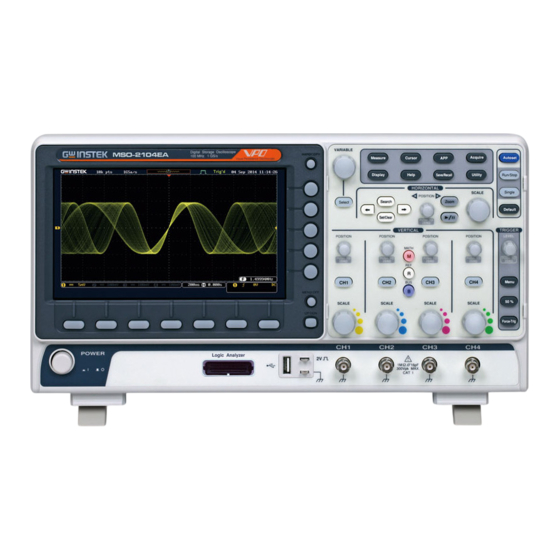
MSO-2000E & 2000EA User Manual Appearance MSO-2000E/2000EA 4-channel models Front Panel Function Variable knob Autoset, Run/Stop, Single keys Hardcopy key and Select key and Default settings Horizontal controls Side menu keys Trigger Menu key controls Bottom Option key menu Vertical keys controls CH1~CH4... -
Page 17: Mso-2000E/2000Ea 2-Channel Models Front Panel
GETTING STARTED MSO-2000E/2000EA 2-channel models Front Panel Function Variable knob Autoset, Run/Stop, Single keys Hardcopy key and Select key and Default settings Horizontal controls Side menu keys Trigger Bottom Menu key controls menu Option key keys Vertical controls Power button CH1~CH2, EXT TRIG Logic Analyzer... - Page 18 MSO-2000E & 2000EA User Manual The side menu and bottom menu keys are used to Menu Keys make selections from the soft-menus on the LCD user interface. To choose menu items, use the 7 Bottom menu keys located on the bottom of the display panel. VARIABLE Digital Storage Oscilloscope GDS-2202E...
- Page 19 MSO-2000E/2000EA. Configures and runs automatic Measure Measure measurements. Configures and runs cursor Cursor Cursor measurements. Configures and runs GW Instek applications. Configures the acquisition mode, Acquire Acquire including Segmented Memory acquisition. Configures the display settings. Display Display Shows the Help menu.
- Page 20 MSO-2000E & 2000EA User Manual Press to Freeze (Stop) or continue Run/Stop Key Run/Stop (Run) signal acquisition (page 44). The run stop key is also used to run or stop Segmented Memory acquisition (page 93). Sets the acquisition mode to single Single Single triggering mode.
- Page 21 GETTING STARTED The Play/Pause key allows you to Play/Pause view each search event in succession – to effectively “play” through each search event. It is also used to play through a waveform/trace in zoom mode. The Search key accesses the search Search Search function menu to set the search...
- Page 22 MSO-2000E & 2000EA User Manual Sets the vertical position of the POSITION Vertical waveform/trace. Push the knob to POSITION reset the vertical position to zero. PUSH TO ZERO Press the CH1~4 key to set and Channel Menu configure the corresponding channel.
- Page 23 GETTING STARTED Accepts input signals. Channel Inputs Input impedance: 1MΩ. Capacitance: 16pF CAT I Type A, 1.1/2.0 compatible. Used USB Host Port for data transfer. Accepts the DUT ground lead for Ground Terminal common ground. The probe compensation output is Probe used for probe compensation.
-
Page 24: Mso-2000E Rear Panel
TO AVOID ELECTRIC SHOCK THE POWER CORD PROTECTIVE GROUNDING CONDUCTOR MUST BE CONNECTED TO GROUND. POWER MAX. 30 Watts DO NOT REMOVE COVERS. REFER SERVICING TO QUALIFIED PERSONNEL. Key lock Power input socket MSO-2000EA Rear Panel USB Device port LAN port AWG channels output Calibration output GEN 2... - Page 25 Kensington security slot Security Slot compatible. Outputs Go-No Go test results Go-No Go (page 258) as a 500us pulse signal. Output Output the GEN1 or GEN2 signal AWG Output GEN 1 from the Arbitrary Wave Generator function, MSO-2000EA only (see page 223).
-
Page 26: Display
MSO-2000E & 2000EA User Manual Display Below is a general description of the main display. As the display changes while activating the different functions of the MSO- 2000E/2000EA, please refer to each function sub-chapters of this user manual for more details. Channel Memory length Memory... - Page 27 GETTING STARTED Bus indicator(B) Reference waveform indicator Math indicator Shows the position of the trigger. Trigger Position Horizontal Status Shows the horizontal scale and position. Date and Time Current date and time (page 201). Shows the trigger level on the graticule. Trigger Level Memory Bar The ratio and the position of the displayed...
- Page 28 MSO-2000E & 2000EA User Manual Trigger source, slope, Trigger voltage and coupling. Configuration Horizontal scale, Horizontal Status horizontal position. For trigger details, see page 148. Channel 1, DC coupling, Channel Status 2V/Div. For channel details, see page 114.
-
Page 29: Set Up
GETTING STARTED Set Up Tilt Stand To tilt, pull the legs forward, as shown below. Tilt To stand the scope upright, push the legs back Stand under the casing as shown below. -
Page 30: Power Up
MSO-2000E & 2000EA User Manual Power Up The MSO-2000E/2000EA accepts line voltages of Requirements 100 ~ 240V at 50 or 60Hz. 1. Connect the power cord to Step the rear panel socket. 2. Press the POWER key. The POWER display becomes active in ~ 30 seconds. -
Page 31: First Time Use
GETTING STARTED First Time Use This section describes how to connect, adjust the Background scale and compensate the probe. Before operating the MSO-2000E/2000EA in a new environment, run these steps to make sure the instrument performs at its full potential. Follow the procedures on the previous page. - Page 32 MSO-2000E & 2000EA User Manual VARIABLE HORIZONTAL SCALE POSITION PUSH TO ZERO VERTICAL TRIGGER POSITION POSITION POSITION POSITION LEVEL MATH PUSH TO PUSH TO PUSH TO PUSH TO PUSH TO ZERO ZERO ZERO ZERO ZERO SCALE SCALE SCALE SCALE POWER 16pF 300Vrms MAX.
- Page 33 GETTING STARTED Under Over Normal Compensation Compensation 9. Start operations Continue with the other operations. Measurement: page 40 Configuration: page 81 Using the Logic Using the Arbitrary Analyzer: page 204. Wave Generator (MSO- 2000EA only): page 220. Applications: page 255 Save/Recall: page 279 File Utilities: page 305 Hardcopy key: page 312...
-
Page 34: How To Use This Manual
MSO-2000E & 2000EA User Manual How to Use This Manual This section describes the conventions used in this Background manual to operate the MSO-2000E/2000EA. Throughout the manual any reference to pressing a menu key refers to the keys directly below or beside any menu icons or parameters. - Page 35 GETTING STARTED Example 1 3. Press a bottom menu key to access the side menu. 4. Press a side menu key to either set a parameter or to access a sub menu. 5. If accessing a sub menu or setting VARIABLE a variable parameter, use the Variable knob to scroll through...
- Page 36 MSO-2000E & 2000EA User Manual 7. Press the desired menu key to select it. The circular arrow will become highlighted. 8. Use the Variable knob to edit the value. Toggling a Menu Parameter 9. Press the bottom menu key to toggle the parameter. Reduce Side Menu...
- Page 37 GETTING STARTED 10. To reduce the side menu, press the corresponding bottom menu that brought up the side menu. For example: Press the Source soft-key to reduce the Source menu. Reduce Lower Menu VARIABLE Measure Cursor Test Acquire Autoset Display Help Save/Recall Utility...
- Page 38 MSO-2000E & 2000EA User Manual VARIABLE Measure Cursor Test Acquire Autose Display Help Save/Recall Utility Run/Sto HORIZONTAL Single SCALE 12. Press the Menu Off key to POSITION Search Zoom Select Default Set/Clear PUSH TO reduce the side menu, press ZERO VERTICAL TRIGGE POSITION...
-
Page 39: Built-In Help
MSO-2000E & 2000EA User Manual Built-in Help The Help key accesses a context sensitive help menu. The help menu contains information on how to use the front panel keys. Panel Operation 1. Press the Help key. The Help display changes to Help mode. -
Page 40: Measurement
MSO-2000E & 2000EA User Manual EASUREMENT Basic Measurement ........... 41 Channel Activation ................. 41 Autoset ..................... 42 Run/Stop ....................44 Horizontal Position/Scale ..............45 Vertical Position/Scale ................47 Automatic Measurement ..........48 Measurement Items ................48 Add Measurement .................. 52 Remove Measurement ................ -
Page 41: Basic Measurement
Advanced Configuration → from page 81 Logic Analyzer→ from page 204 Arbitrary Wave Generator (MSO-2000EA only)→ from page 220 Applications→ from page 255 Before operating the oscilloscope, please see the Getting Started chapter, page 11. -
Page 42: Autoset
MSO-2000E & 2000EA User Manual To de-activate a channel, press De-activate the corresponding channel key Channel again. If the channel menu is not open, press the channel key twice (the first press shows the Channel menu). To activate the default state, Default Setup Default press Default (this will reset the... - Page 43 MEASUREMENT Before After 3. To undo Autoset, press Undo Autoset from the bottom menu. 4. Choose between Fit Screen Mode Change modes and AC Priority Mode from the bottom menu. 5. Press the Autoset key again to use Autoset Autoset in the new mode. Fit Screen Mode AC Priority Autoset does not work in the following situations:...
-
Page 44: Run/Stop
MSO-2000E & 2000EA User Manual Run/Stop By default, the waveform on the display is Background constantly updated (Run mode). Freezing the waveform by stopping signal acquisition (Stop mode) allows flexible observation and analysis. To enter Stop mode, two methods are available: pressing the Run/Stop key or using the Single Trigger mode. -
Page 45: Horizontal Position/Scale
MEASUREMENT Horizontal Position/Scale For more detailed configuration, see page 106. The horizontal position knob Set Horizontal POSITION moves the waveform left and Position right. PUSH TO ZERO Pressing the horizontal position Set Horizontal POSITION knob will reset the horizontal Position to 0 position to 0. - Page 46 MSO-2000E & 2000EA User Manual Position Indicator The horizontal position is shown at the bottom of the display grid to the right of the H icon. To select the timebase, turn the Select Horizontal SCALE horizontal SCALE knob; left (slow) or Scale right (fast).
-
Page 47: Vertical Position/Scale
MEASUREMENT Vertical Position/Scale For more detailed configuration, see page 114. To move the waveform up or down, turn Set Vertical POSITION the vertical position knob for each channel. Position PUSH TO ZERO Push the vertical position knob to POSITION reset the position to 0. As the waveform moves, the vertical position of the cursor PUSH TO... -
Page 48: Automatic Measurement
MSO-2000E & 2000EA User Manual Automatic Measurement The automatic measurement function measures and updates major items for Voltage/Current, Time, and Delay type measurements. Measurement Items V/I Measurements Time Meas. Delay Meas. Overview Frequency Pk-Pk Period RiseTime Amplitude FallTime High +Width -Width Mean Dutycycle... - Page 49 MEASUREMENT Difference between the Amplitude global high value and the global low value, measured over the entire waveform or gated region. (=high − low) Global high voltage. See High page 57 for details. Global low voltage. See page 57 for details. The arithmetic mean value is Mean calculated for all data...
- Page 50 MSO-2000E & 2000EA User Manual Rise overshoot ROVShoot Fall overshoot FOVShoot Rise preshoot RPREShoot Fall preshoot FPREShoot Frequency of the waveform. Time Frequency Measurement Waveform cycle time. Period (=1/Freq) The time required for the RiseTime leading edge of the first pulse to rise from the low reference value to the high reference value.
- Page 51 MEASUREMENT Ratio of signal pulse Duty Cycle compared with whole cycle. =100x (Pulse Width/Cycle) Measures the number of +Pulses positive pulses. Measures the number of -Pulses negative pulses. Measures the number of +Edges positive edges. Measures the number of -Edges negative edges.
-
Page 52: Add Measurement
MSO-2000E & 2000EA User Manual Time between: Source 1 first rising edge and Source 2 last falling edge. Time between: Source 1 first falling edge and Source 2 last rising edge. Time between: Source 1 first falling edge and Source 2 last falling edge. - Page 53 MEASUREMENT 3. Choose either a V/I, Time or Delay measurement from the side menu and choose the type of measurement you wish to add. Pk-Pk, Max, Min, Amplitude, High, (Voltage/ Low, Mean, Cycle Mean, RMS, Current) Cycle RMS, Area, Cycle Area, ROVShoot, FOVShoot, RPREShoot, FPREShoot Frequency, Period, RiseTime,...
- Page 54 MSO-2000E & 2000EA User Manual 5. To set the source, press either the Source1 or Source2 key from the side menu and choose the source. Source1: CH1~CH4, Math, D0~D15 Range Source2: CH1~CH4, Math Source 2 is only applicable to Delay (Note) measurements.
-
Page 55: Remove Measurement
MEASUREMENT Remove Measurement Individual measurements can be removed at any time using the Remove Measurement function. 1. Press the Measure key. Remove Measure Measurement Item 2. Press Remove Measurement from the bottom menu. 3. Press Select Measurement and select the item that you want to remove from the measurement list. -
Page 56: Display All Mode
MSO-2000E & 2000EA User Manual 3. Choose one of the gating modes from the side menu: Off (full record), Screen, Between Cursors. If Between Cursors is selected, the Page 63 Cursors On cursor positions can be edited by Screen using the cursor menu. Display All mode Display All mode shows and updates all items from Voltage and Time type measurements. -
Page 57: High Low Function
MEASUREMENT To remove the measurement results, Remove Measurements press OFF. Delay type measurements are not available in this Delay mode as only one channel is used as the source. Measurements Use the individual measurement mode (page 52) instead. Only Frequency, Period, +Width, -Width and Duty Digital channels Cycle measurements are supported for the digital channels D0~D15. - Page 58 MSO-2000E & 2000EA User Manual Uses histograms to determine the Histogram high-low values. This mode ignores any pre-shoot or overshoot values. This mode is particularly useful for pulse-type waveforms high Sets the high-low values as the Min-max minimum or maximum measured values.
-
Page 59: Statistics
MEASUREMENT To return to the default High-Low Restore Default High-Low settings, press Set to Defaults. Settings Statistics The Statistics function can be used to view a Background number of statistics for the selected automatic measurements. The following information is displayed with the Statistics function: Currently measured value Value The mean value is calculated from... - Page 60 MSO-2000E & 2000EA User Manual The variance of the currently Standard measured value from the mean. Deviation The standard deviation equals the squared root of the variance value. Measuring the standard deviation can, for example, determine the severity of jitter in a signal. The number of samples used to determine the standard deviation can be user-defined.
-
Page 61: Reference Levels
MEASUREMENT To reset the standard deviation Reset Statistics calculations, press Reset Statistics. Reference Levels The reference level settings determine the Background measurement threshold levels for some measurements like the Rise Time measurement. High Ref: Sets the high reference level. Mid Ref: Sets the middle reference for the first and second waveforms. - Page 62 MSO-2000E & 2000EA User Manual 0.0% ~ 100% High Ref 0.0% ~ 100% Mid Ref 0.0% ~ 100% 0.0% ~ 100% Low Ref 4. Press Set to Defaults to set the Default Settings reference levels back to the default settings.
-
Page 63: Cursor Measurement
MEASUREMENT Cursor Measurement Horizontal or vertical cursors are used to show the position and values of waveform measurements and math operation results. These results cover voltage, time, frequency and other math operations. When the cursors (horizontal, vertical or both) are activated, they will be shown on the main display unless turned off. - Page 64 MSO-2000E & 2000EA User Manual 4. The cursor position information appears on the top left hand side of the screen Hor. position, Voltage/Current Cursor Hor. position, Voltage/Current Cursor Delta (difference between cursors) dV/dt or dI/dt 5. Use the Variable knob to move the VARIABLE movable cursor(s) left or right.
- Page 65 MEASUREMENT Example Horizontal cursors FFT cursors can use different units. For FFT details, see page Hor. position, dB/Voltage Cursor Hor. Position, dB/Voltage Cursor Delta (difference between cursors) dV/dt or d/dt Example Horizontal cursors XY mode cursors measure a number of X by Y XY Mode measurements.
- Page 66 MSO-2000E & 2000EA User Manual Time, rectangular, polar co- Cursor ordinates, product, ratio. Time, rectangular, polar co- Cursor ordinates, product, ratio. Delta (difference between cursors) Example Horizontal cursors...
-
Page 67: Use Vertical Cursors
MEASUREMENT Use Vertical Cursors 1. Press the Cursor key twice. Panel Operation/ Cursor Range 2. Press V Cursor from the bottom menu if it is not already selected. 3. When the V Cursor is selected, repeatedly pressing the V Cursor key or the Select key will toggle which vertical cursor is selected. - Page 68 MSO-2000E & 2000EA User Manual 6. To change the units of the vertical Select Units position, press V Unit. Base (source wave units), % (ratio) Units 7. To set the 0% and 100% ratio Base or Ratio references for the current cursor Reference position, press Set Cursor Positions As 100%.
- Page 69 MEASUREMENT Example Horizontal Vertical cursors cursors XY mode cursors measure a number of X by Y XY Mode measurements. See page 85. Rectangular, polar co-ordinates, Cursor product, ratio. Rectangular, polar co-ordinates, Cursor product, ratio. Delta (difference between cursors)
- Page 70 MSO-2000E & 2000EA User Manual Example Horizontal cursors Vertical cursors...
-
Page 71: Math Operation
MEASUREMENT Math Operation Basic Math Overview & Operators The Math function performs basic math functions Background (addition, subtraction, multiplication, division) on the input signals or the reference waveforms. The resultant waveform will be shown on the screen in real-time. Adds the amplitude of two signals. Addition (+) CH1~4, Ref1~4 Source... - Page 72 MSO-2000E & 2000EA User Manual 4. Press Operator to choose the math operation. +, -, ×, ÷ Range 5. Select Source 2 from the side menu. CH1~4, Ref1~4 Range 6. The math measurement result appears on the display. The vertical scale of the math waveform appears at the bottom of the screen.
-
Page 73: Fft Overview & Window Functions
MEASUREMENT To change the unit/div settings, press Unit/div, then use the Variable knob to change the unit/div. The units that are displayed depend on which operator has been selected, and whether the probe for the selected channel has been set to voltage or current. -
Page 74: Fft Operation
MSO-2000E & 2000EA User Manual Frequency resolution Good Hamming Amplitude resolution Not good Frequency measurement on Suitable for..periodic waveforms Frequency resolution Very good Rectangular Amplitude resolution Bad Single-shot phenomenon Suitable for..(this mode is the same as having no window at all) Frequency resolution Bad Blackman Amplitude resolution Very good... - Page 75 MEASUREMENT 5. Press the Window key from the side menu and select the window type. Hanning, Hamming, Rectangular, Range and Blackman. 6. The FFT result represents the frequency- domain representation of a signal. Hence, the horizontal scale changes from time to frequency, and the vertical scale from voltage/current to dB/RMS.
-
Page 76: Advanced Math Overview
MSO-2000E & 2000EA User Manual To move the FFT waveform Horizontal horizontally, press Horizontal until the Position and Scale Frequency parameter is highlighted and then use the Variable knob. 0Hz ~ half of the sampling Range frequency To select the horizontal scale of the FFT waveform, press Horizontal repeatedly until the Hz/div parameter is highlighted and then use the... -
Page 77: Advanced Math Operation
MEASUREMENT Adds an operator or parenthesis to the function Operator expression. +, -, *, /, (, ), !(, <, >, <=, >=, ==, !=, Operator ||, && Adds a value to the expression. Figure Integers, floating point, or floating Figure point with exponent values. - Page 78 MSO-2000E & 2000EA User Manual 5. Press Clear to clear the expression entry area. 6. Use the Variable knob and the Select VARIABLE key to create an expression. Use the Variable knob to highlight a source, function, variable, operator, figure or measurement in orange.
- Page 79 MEASUREMENT Example: CH1 + CH2 Source1 Advanced Math Source2 9. Press VAR1 or VAR2 to set Set the VAR1 & VAR1/VAR2 if they were used in VAR2 the expression created previously. 10. Press Mantissa. Use the Left and Right arrow keys to select a digit and use the variable knob to set the value of the selected digit.
- Page 80 MSO-2000E & 2000EA User Manual To clear the advanced math result MATH Clear Advanced from the display, press the Math key Math again.
-
Page 81: Advanced Configuration
ADVANCED CONFIGURATION DVANCED CONFIGURATION Acquisition ..............84 Select Acquisition Mode ................ 84 Show Waveform in XY Mode ............. 85 Set the Record Length ................87 Segmented Memory Acquisition ........ 89 Segments Display ................... 91 Set the Number of Segments ............... 92 Run Segmented Memory ............... - Page 82 MSO-2000E & 2000EA User Manual Limit Bandwidth ................... 117 Expand by Ground/Center ..............118 Select Probe Type ................. 119 Select Probe Attenuation Level ............120 Set the Deskew ..................120 Bus Key Configuration ..........122 Bus Display .................... 122 Serial Bus Overview ................124 UART Serial Bus Configuration ............
- Page 83 ADVANCED CONFIGURATION Copying Search Event To/From Trigger Events ......192 Search Event Navigation..............192 Save Search Marks ................193 Setting/Clearing Single Search Events ..........194 FFT Peak....................195 System Settings and Miscellaneous Settings ....199 Select Menu Language ................. 199 View System Information ..............200 Erase Memory ..................
-
Page 84: Acquisition
MSO-2000E & 2000EA User Manual Acquisition The Acquisition process samples the analog input signals and converts them into digital format for internal processing. Select Acquisition Mode The acquisition mode determines how the samples Background are used to reconstruct a waveform. This is the default acquisition Sample mode. -
Page 85: Show Waveform In Xy Mode
ADVANCED CONFIGURATION 3. Select an acquisition mode from the side menu. 4. If Average was chosen, set the number of samples to be used for the average function. Mode Sample, Peak Detect, Average Average 2, 4, 8, 16, 32, 64, 128, sample Example Sample... - Page 86 MSO-2000E & 2000EA User Manual 1. Connect the signals to Connection Channel 1 (X-axis) and Channel 2 (Y-axis) or Channel 3 (X2-axis) and Channel 4 (Y2-axis). 2. Make sure a channel pair is active (CH1&CH2 or CH3&CH4). Press the Channel key if necessary. A channel is active if the channel key is lit.
-
Page 87: Set The Record Length
ADVANCED CONFIGURATION To move the XY waveform position, use the vertical position knob: Channel 1 knob moves the XY waveform horizontally and Channel 2 knob moves the XY waveform vertically. Similarly, the X2 and Y2 axis can be positioned using the channel 3 and channel 4 vertical position knobs. - Page 88 MSO-2000E & 2000EA User Manual ✓ ✓ ✓ ✓ ✓ ✓ ✓ ✓ 100k ✓ ✓ ✓ ✗ ✓ ✓ ✗ ✗ Panel Operation 1. Press the Acquire key. Acquire 2. Press the Record Length key on the bottom menu and choose the record length.
-
Page 89: Segmented Memory Acquisition
ADVANCED CONFIGURATION Segmented Memory Acquisition The advanced segmented memory utility allows the scope memory to be divided into different segments. Each time the scope is triggered, it only acquires data for one segment of memory at a time. This allows you to optimize the scope memory to only perform signal acquisition during important signal events. - Page 90 MSO-2000E & 2000EA User Manual Segmented memory acquisition example: Segment Segment Segment Segment Segment Segment As shown above, the memory is divided into segments to increase the number of events that can be effectively captured with the same acquisition memory. Also notice that the scope doesn’t need to rearm the trigger between each segment, this makes the segmented memory function especially useful for high speed signals.
-
Page 91: Segments Display
ADVANCED CONFIGURATION Segments Display Progress Indicator Run/Stop Indicator Progress Indicator Indicates the number of segments that have to been captured relative to the set number of segments. Stop: The segments have finished Run/Stop Indicator acquiring or have been stopped. Run: The scope is ready to acquire segments. -
Page 92: Set The Number Of Segments
MSO-2000E & 2000EA User Manual Set the Number of Segments Before the Segment function can be used, set the Note trigger settings as appropriate for the signal you wish to use. The number of segments that can be used depends wholly on the record length. See page 87 to set the record length. -
Page 93: Run Segmented Memory
ADVANCED CONFIGURATION Run Segmented Memory Before the Segmented Memory function can be Background used, set the trigger settings as appropriate for the signal you wish to use. See page 148 for configuring the trigger settings. 1. Toggle Segments On from the bottom menu. Run Segments ... - Page 94 MSO-2000E & 2000EA User Manual Alternatively, the Run/Stop key can Run/Stop be pressed. 5. The Stop Indicator will be shown when in the Stop mode. Progress Indicator Stop Indicator Segment (Stop )icon The scope is now ready to navigate or analyze the acquired segments.
-
Page 95: Navigate Segmented Memory
ADVANCED CONFIGURATION Navigate Segmented Memory After the segmented memory acquisitions have Background been captured you can navigate through each segment one at a time. 1. Press Select Segments from the Operation bottom menu. This key will be available in the Stop mode. 2. -
Page 96: Measurement On Segments
MSO-2000E & 2000EA User Manual 2. Press the Play/Pause key to run through the acquired segments in numerical order. Press the Play/Pause key again to pause the playback. When the scope has played through to the last segment, pressing the Play/Pause key again will play through each segment again in reverse order. - Page 97 ADVANCED CONFIGURATION This function will bin the Statistics measurement results of a single automatic measurement into a user-defined number of bins. This allows you to easily view statistics for a large number of segments. For example, the statistics function will display the number of results for each bin and the measurement range of each bin for the selected...
- Page 98 MSO-2000E & 2000EA User Manual 1. Press Analyze Segments from the Operation Segments menu. Note: This key will only be available in the Stop mode. 2. Press Segments Measure. 3. Select either the statistics or the measurement list from the side menu. Statistics List 4.
- Page 99 ADVANCED CONFIGURATION Statistics Results This function will bin the measurement results of the selected automatic measurement into a user- defined number of bins. 7. To select the number of bins for the Setup statistics, press Divided by and select the number of bins with the Variable knob.
-
Page 100: Segment Info
MSO-2000E & 2000EA User Manual Example: Measurement Measurement types List Select cursor Measurement results Segment Info 1. Press Analyze Segments from the Operation bottom menu. Note: This key will only be available in the Stop mode. 2. Press Segments Info. 3. -
Page 101: Display
ADVANCED CONFIGURATION Display The Display menu defines how the waveforms and parameters appear on the main LCD display. Display Waveform as Dots or Vectors When the waveform is displayed on the screen, it Background can be displayed as dots or vectors. Panel Operation 1. -
Page 102: Set The Intensity Level
MSO-2000E & 2000EA User Manual 2. To set the persistence time, press the Persistence menu button on the bottom bezel. 3. Use the Variable knob to select a persistence time. 16ms, 30ms, 60ms, 120ms, 240ms, Time 0.5s, 1s, 2s,~4s, Infinite, Off To clear persistence, press Clear Clear Persistence. -
Page 103: Select Display Graticule
ADVANCED CONFIGURATION 4. To set the graticule intensity, press Graticule Graticule Intensity from the side menu and edit the Intensity intensity value. 10~100% Range Example Graticule Intensity 100% Graticule Intensity 10% 5. To set the LCD backlight intensity, press Backlight Intensity Backlight Intensity from the side menu and edit the intensity value. -
Page 104: Freeze The Waveform (Run/Stop)
MSO-2000E & 2000EA User Manual 3. From the side menu choose the graticule display type. Full : Shows the full grid; X and Y axis for each division. Grid : Show the full grid without the X and Y axis. Cross Hair : Shows only the center X and Y frame. -
Page 105: Turn Off Menu
ADVANCED CONFIGURATION POSITION Turn Off Menu PUSH TO ZERO Panel Operation 1. Press the Menu Off key below the side menu keys to reduce a menu. The menu SCALE key needs to be pressed each time to reduce one menu. See page 34 for more information. -
Page 106: Horizontal View
MSO-2000E & 2000EA User Manual Horizontal View This section describes how to set the horizontal scale, position, and waveform display mode. Move Waveform Position Horizontally POSITION Panel Operation The horizontal position knob moves the waveform left/right. PUSH TO ZERO As the waveform moves, a position indicator on the on the top of the display indicates the horizontal position of the waveform in memory. -
Page 107: Select Horizontal Scale
ADVANCED CONFIGURATION Select Horizontal Scale SCALE To select the timebase (time/div), turn Select Horizontal the horizontal Scale knob; left (slow) Scale or right (fast). Range 1ns/div ~ 100s/div, 1-2-5 increment The timebase indicator updates as the horizontal scale is adjusted. Horizontal Timebase position... -
Page 108: Select Waveform Update Mode
MSO-2000E & 2000EA User Manual Select Waveform Update Mode The display update mode is switched Background automatically or manually according to the timebase and trigger. Updates the whole displayed waveform at Normal once. Automatically selected when the timebase (sampling rate) is fast. ≤50ms/div Timebase all modes... -
Page 109: Zoom Waveform Horizontally
ADVANCED CONFIGURATION 2. Press Mode from the bottom menu and select Auto (Untriggered Roll) to let the equipment choose between Normal and Roll mode or Normal to force the update mode to Normal at all times. Zoom Waveform Horizontally When in Zoom mode, the screen is split into 2 Background sections. - Page 110 MSO-2000E & 2000EA User Manual Variable Position knob. VARIABLE The horizontal position will be shown on the Horizontal Position icon. Horizontal Scale To change the horizontal scale, press Horizontal Time/Div and use the Variable Position knob. VARIABLE The scale will be shown on the Horizontal Time/Div icon.
-
Page 111: Play/Pause
ADVANCED CONFIGURATION Sensitivity Fine, Coarse To reset both the zoom and horizontal Reset the Zoom & Horizontal position, press Reset Zoom & H POS to Position To go back to the original view, press Exit Zoom the Zoom key again. Play/Pause The Play/Pause key can be used to play through Background... - Page 112 MSO-2000E & 2000EA User Manual 2. The scope will go into the Zoom Play mode and begin to scroll through the acquisition (from left to right). The full-record length waveform will be shown at the top and the zoomed section will be shown at the bottom.
- Page 113 ADVANCED CONFIGURATION Speed Speed POSITION Right Left PUSH TO ZERO To reset both the zoom position and Reset the Zoom Position horizontal position, press Reset Zoom & H POS to 0s. Press the Play/Pause key to pause or Pause resume playing the waveform. Reverse Direction Press the Play/Pause key when at the end of the record length to play back through the waveform in reverse.
-
Page 114: Vertical View (Channel)
MSO-2000E & 2000EA User Manual Vertical View (Channel) This section describes how to set the vertical scale, position, and coupling mode. Move Waveform Position Vertically POSITION Panel Operation 1. To move the waveform up or down, turn the vertical position knob for each channel. -
Page 115: Select Vertical Scale
ADVANCED CONFIGURATION Select Vertical Scale SCALE Panel Operation To change the vertical scale, turn the vertical SCALE knob; left (down) or right (up). The vertical scale indicator on the bottom left of the display changes accordingly for the specific channel. 1mV/div ~ 10V/div. -
Page 116: Input Impedance
MSO-2000E & 2000EA User Manual Ground coupling mode. The display shows only the zero voltage level as a horizontal line. Example Observing the AC portion of the waveform using AC coupling DC coupling AC coupling Input Impedance The input impedance of the MSO-2000E/2000EA is Background fixed at 1MΩ. -
Page 117: Limit Bandwidth
ADVANCED CONFIGURATION Limit Bandwidth Bandwidth limitation puts the input signal into a Background selected bandwidth filter. This function is useful for cutting out high frequency noise to see a clear waveform shape. The bandwidth filters available are dependent on the bandwidth of the oscilloscope model. Also refer to the digital filter application, page 267. -
Page 118: Expand By Ground/Center
MSO-2000E & 2000EA User Manual Expand by Ground/Center When the voltage scale is changed, the Expand Background function designates whether the signal expands from the center of the screen or from the signal ground level. Expand by center can be used to easily see if a signal has a voltage bias. -
Page 119: Select Probe Type
ADVANCED CONFIGURATION Expand by Ground Expand by Ground Expand by Center Expand by Center Select Probe Type A signal probe can be set to voltage or current. Background Panel Operation 1. Press the Channel key. 2. Press Probe from the bottom menu. 3. -
Page 120: Select Probe Attenuation Level
MSO-2000E & 2000EA User Manual Select Probe Attenuation Level An oscilloscope probe has an attenuation switch to Background lower the original DUT signal level to the oscilloscope input range, if necessary. The probe attenuation selection adjusts the vertical scale so that the voltage level on the display reflects the real value on a DUT. - Page 121 ADVANCED CONFIGURATION 3. Press Deskew on the side menu and use the Variable knob to set the deskew time. Alternatively, press Set to 0s to reset the deskew time. -50ns~50ns, 10ps increments Range 4. Repeat the procedure for another channel if necessary.
-
Page 122: Bus Key Configuration
MSO-2000E & 2000EA User Manual Bus Key Configuration The Bus key is used to configure the Serial bus and parallel bus inputs. The bus inputs can be either analog or digital. The Bus menu also features event tables to track and save your bus data. The Bus key is used in conjunction with the Bus trigger (page 173) to decode serial or parallel bus signals. - Page 123 ADVANCED CONFIGURATION Parallel All read words are shown in purple (no clock) or white (a clock is defined among the channels). Purple = Error frame, Data length control CAN: (DLC), Overload. Yellow = Identifier. Cyan = Data. Orange = CRC. Red = Bit stuffing error LIN: Purple = Break, Sync and Checksum...
-
Page 124: Serial Bus Overview
MSO-2000E & 2000EA User Manual Serial Bus Overview The Serial Bus includes support for 5 common serial interfaces UART, I C, SPI, Parallel, CAN and LIN. Each interface is fully configurable to accommodate variations in the basic protocols. Each input can be displayed as binary, hexadecimal or ASCII. An event table can also be created to aid in debugging. - Page 125 ADVANCED CONFIGURATION The SPI (Serial Interface Peripheral) bus is fully configurable to accommodate the wide variety of SPI interfaces. This bus is only available on 4 channel models. SCLK, SS, MOSI, MISO Inputs SCLK, SS, MOSI, MISO Threshold Configuration SCLK edge, SS logic level, Word size, Bit order SS Active, MOSI, MISO, Trigger On...
-
Page 126: Uart Serial Bus Configuration
MSO-2000E & 2000EA User Manual UART Serial Bus Configuration The UART bus menu is designed to decode RS-232 and other common RS-232 variants such as RS-422, RS-485. The software configuration is also flexible enough to decode the many proprietary protocols based on RS-232. Basic RS-232 protocol uses single-ended data Background transmissions. - Page 127 ADVANCED CONFIGURATION 2. Press the BUS key. 3. Press Bus from the bottom menu and choose the UART serial bus on the side menu. 4. Press either Analog Source or Digital Source to choose whether the sources for the UART bus are analog or digital.
-
Page 128: I 2 C Serial Bus Interface
MSO-2000E & 2000EA User Manual Baud Rate 50, 75, 110, 134, 150, 300, 600, 1200, 1800, 2000, 2400, 3600, 4800, 7200, 9600, 14400, 15200, 19200, 28800, 31250, 38400, 56000, 57600, 76800, 115200, 128000, 230400, 460800, 921600, 1382400, 1843200, 2764800 Data Bits 8 (fixed) Odd, Even, None Parity On, Off... - Page 129 ADVANCED CONFIGURATION Analog SCLK Digital 2. Press the Bus key. 3. Press Bus from the bottom menu and choose I C from the side menu. 4. Press either Analog Source or Digital Source to choose whether the sources for the I C bus are analog or digital.
-
Page 130: Spi Serial Bus Interface
MSO-2000E & 2000EA User Manual SPI Serial Bus Interface The serial peripheral interface (SPI) is a full duplex 4 wire synchronous serial interface. The 4 signals lines: Serial clock line (SCLK), slave select (SS), Master output/slave input (MOSI, or SIMO) and the Master input/slave output (MISO, or SOMI). The word size is configurable from 4 to 32 bits. - Page 131 ADVANCED CONFIGURATION 5. Press Define Inputs from the lower Define Inputs menu. 6. From the side menu choose the SCLK, SS, MOSI and MISO inputs. CH1~CH4 or D0~D15 * SCLK CH1~CH4 or D0~D15 * OFF, CH1~CH4 or OFF, D0~D15 * MOSI OFF, CH1~CH4 or OFF, D0~D15 * MISO...
-
Page 132: Can Serial Bus Interface
MSO-2000E & 2000EA User Manual CAN Serial Bus Interface The controller area network (CAN) bus is a half duplex 2 wire synchronous serial interface. The CAN bus is a multi-master communication system that relies on arbitration to solve contention issues. The MSO-2000E supports both CAN 2.0A and 2.0B. The CAN bus uses two wires, CAN-High and CAN-Low. -
Page 133: Lin Serial Bus Interface
ADVANCED CONFIGURATION 5. Press Define Inputs from the lower Define Inputs menu. 6. From the side menu choose the CAN Input inputs and the signal type. CAN Input CH1~CH4 or D0~D15 * CAN_H, CAN_L, Tx, Rx. Signal Type *Depending on your choice at step 4 above. The Sample Point soft-key indicates the sampling Note position of each bit. - Page 134 MSO-2000E & 2000EA User Manual Analog LIN input Digital 2. Press the Bus key. 3. Press Bus from the bottom menu and choose the LIN serial bus. 4. Press either Analog Source or Digital Source to choose whether the source for the LIN bus is analog or digital.
-
Page 135: Parallel Bus
ADVANCED CONFIGURATION 7. Press Configure from the bottom menu. 8. From the side menu select configuration items. 1.2kbps, 2.4kbps, 4.8kbps, Bit Rate 9.6kbps, 10.417kbps, 19.2kbps LIN Standard V1.x, V2.x, Both On, Off Include Parity Bits with Id Parallel Bus The digital channels can be configured as a parallel bus. The number of bits that defines the bus as well as which bit is used as the bus clock can also be configured. - Page 136 MSO-2000E & 2000EA User Manual 3. Press the Bus soft-key and select Parallel from the side menu. 4. Press Define Inputs from the bottom menu. 5. Press Number of Bits from the side menu and select the number of bits for the data bus.
-
Page 137: Bus Decoding
ADVANCED CONFIGURATION Bus Decoding The bus that is displayed on the screen or in the Background event tables can be set to either hex or binary formats. Press Bus Display from the Bus Operation menu and choose either Hex or Binary from the side menu. - Page 138 MSO-2000E & 2000EA User Manual 1.4V 2.5V 5.0V CMOS 1.65V 3.3V CMOS 1.25V 2.5V CMOS -1.3V 3.7V PECL 4. Press Threshold to set a user defined threshold for the currently selected input. For the analog channels, the threshold level depends on the vertical scale : Scale Range...
-
Page 139: Serial Or Parallel Bus Event Tables
ADVANCED CONFIGURATION Serial or Parallel Bus Event Tables The serial bus event tables list when each data Background event on the bus occurred. The data is displayed as either hex or binary, depending on the bus display settings. Event tables can be saved to disk in a CSV format. The files will be named “Event_TableXXXX.CSV”, where XXXX is a number from 0000 to 9999. - Page 140 MSO-2000E & 2000EA User Manual Save Event Table 4. To save the event table, press Save Event Table. The Event table will be saved to the current file path in a CSV format. See page 143 for details. Use the variable knob to scroll through the event table.
- Page 141 ADVANCED CONFIGURATION Example: Time of trigger Address C Data Detail Select cursor Data at cursor position Note Data Detail is only available with the I C bus. Example: MOSI MISO Time of trigger SPI Event table Select cursor Example: Identifier CRC Missing ACK Time of trigger Data...
- Page 142 MSO-2000E & 2000EA User Manual Example: Identifier Data Errors Time of trigger Parity Checksum LIN Event table Select cursor Example: Time of event Parallel Bus Event table Event data...
-
Page 143: Event Tables Format
ADVANCED CONFIGURATION Event Tables Format Each bus type (UART, I C, SPI, Parallel, CAN and LIN) can have an event table saved containing each bus event as a .CSV file. An event is defined as a packet/frame/word or associated set of data being successfully read according to the specific operating conditions of each bus (Start of frame, acknowledgements, checksums, etc …). -
Page 144: Adding A Label To A Bus
MSO-2000E & 2000EA User Manual Example Below shows the data associated with an SPI event table in a spreadsheet. Time MOSI MISO -11.60us 0D87 0D87 -10.16us 06C0 06C0 -8.720us 8343 -7.282us 243 -5.840us 0C88 0C88 Adding a Label to a Bus A Label can be added to the buses. - Page 145 ADVANCED CONFIGURATION 4. The Edit Label window appears. 5. Use the Variable knob to highlight a character. VARIABLE Press Enter Character to select a number or letter. Press Back Space to delete a character. Press Editing Completed to create the new label and return to the previous menu.
-
Page 146: Using Cursors With The Serial Or Parallel Bus
MSO-2000E & 2000EA User Manual 6. The label will appear next to the bus indicator. Below, the label “ACK” was created for the bus. The bus is labeled as ACK Press Label Display to toggle the label Remove Label on or off. Using Cursors with the Serial or Parallel Bus The cursors can be used to read bus values at any Background... - Page 147 ADVANCED CONFIGURATION 3. The cursor position information appears on the top left hand side of the screen. Example: I C cursors. Hor. position, Bus value(s) Cursor Hor. position, Bus value(s) Cursor 4. Use the Variable knob to move the VARIABLE movable cursor(s) left or right.
-
Page 148: Trigger
MSO-2000E & 2000EA User Manual Trigger The trigger configures the conditions for when the MSO- 2000E/2000EA captures a waveform. Trigger Type Overview The edge trigger is the simplest trigger type. An Edge edge trigger triggers when the signal crosses an amplitude threshold with either a positive or negative slope. - Page 149 ADVANCED CONFIGURATION Delay trigger example (by time) Edge trigger Delay Source Delay time length First triggering point Triggers when the pulse width of the signal is less Pulse Width than, equal, not equal or greater than a specified pulse width. Pulse width Extracts a sync pulse from a video format signal, Video...
-
Page 150: Trigger: Types And Sources
MSO-2000E & 2000EA User Manual Triggers when the signal stays high, low or either Timeout for a designated amount of time. The trigger level determines when a signal is high or low. Trigger level threshold Timer Triggering point Triggers on SPI, UART, I2C, Parallel, CAN or LIN bus events. -
Page 151: Trigger Parameter Overview
ADVANCED CONFIGURATION *Only for two channels model. **The source (analog or digital) is assigned from the Bus menu. Trigger Parameter Overview All the following parameters are common for all the trigger types unless stated otherwise. Channel 1 ~ 4 input signals Trigger Source CH1 ~ 4 Except for: Logic... - Page 152 MSO-2000E & 2000EA User Manual Inter-Integrated Circuit Serial Peripheral Bus Parallel bus Parallel Controller Area Network bus Local Interconnect Network The Source Bus is not configurable from the Trigger Note menu. The field is automatically filled according to the Bus menu configuration (see page 122). The MSO-2000E/2000EA generates an Trigger Mode Auto (un-...
- Page 153 ADVANCED CONFIGURATION DC coupling. Coupling (Edge, Delay, AC coupling. Blocks DC components Timeout) from the trigger circuits *. High frequency filter, above 70kHz *. HF reject Low frequency filter, below 70kHz *. LF reject Reject noise DC coupling with low sensitivity to reject noise.
- Page 154 MSO-2000E & 2000EA User Manual Press Choose Preset to Choose Preset select a pre-set logic threshold. Threshold Logic Type 1.4V 2.5V 5.0V CMOS 1.65V 3.3V CMOS 1.25V 2.5V CMOS -1.3V 3.7V PECL Setting the trigger levels for the digital sources will Note also change the threshold levels set in the Logic Analyzer menu (page 214).
- Page 155 ADVANCED CONFIGURATION Sets the amplitude threshold level for the pulse Threshold widths. (Pulse Width) –XXV ~ +XXV, user-set level Threshold 1.4V Set to TTL -1.3V Set to ECL Set to 50% Sets the threshold to 50% (Only when the trigger source is digital): Adjusts the amplitude Threshold threshold for the pulse...
- Page 156 MSO-2000E & 2000EA User Manual SEquential Couleur A Memoire SECAM Positive polarity (triggered on the high Polarity to low transition) (Pulse Width, Negative polarity (triggered on the low Video) to high transition) Positive polarity (positive runt) Polarity (Pulse Runt) Negative polarity (negative runt) Either (either negative or positive runt) Selects the trigger point in the video signal.
- Page 157 ADVANCED CONFIGURATION Selects the conditions for the parallel bus trigger. Data (Bus) A Binary or Hexadecimal word. Parallel Sets the upper threshold limit. Threshold (Pulse Runt) Sets the lower threshold limit. Sets the High threshold. Threshold (Rise & Fall) Sets the Low threshold. Stays High Triggers when the input signal stays Trigger When (Timeout)
-
Page 158: Setup Holdoff Level
MSO-2000E & 2000EA User Manual Setup Holdoff Level The holdoff function defines the waiting period Background before the MSO-2000E/2000EA starts triggering again after a trigger point. The holdoff function ensures a stable display if there are a number of points in a periodic waveform that can be triggered. -
Page 159: Setup Trigger Mode
ADVANCED CONFIGURATION Setup Trigger Mode The trigger mode can be set to Normal or Auto Background (untriggered roll). The triggering mode applies to all the trigger types. Panel Operation 1. Press the Trigger menu key. Menu 2. Press Mode from the bottom menu to change the triggering mode. - Page 160 MSO-2000E & 2000EA User Manual Channel 1 ~ 4 (Alternate On/Off), Range EXT (Ext Probe: Volt/Current, Attenuation: 1mX~1kX, CH2 models only), AC Line, D0 ~ D15. 6. Press Coupling from the bottom bezel menu to select the trigger coupling or frequency filter settings.
-
Page 161: Using Advanced Delay Trigger
ADVANCED CONFIGURATION 10. Set the external trigger level using the side menu. 00.0V~ 5 screen divisions Analog channel Set to TTL 1.4V Range Set to ECL -1.3V Set to 50% -5.00V~ +5.00V Digital channel 1.4V Range 5.0V CMOS 2.5V 3.3V CMOS 1.65V 2.5V CMOS 1.25V... - Page 162 MSO-2000E & 2000EA User Manual 4. Select Delay from the side menu. The delay trigger indicator appears at the bottom of the display. From left: Delay trigger indicator (D), edge trigger (A), edge slope, edge level, edge coupling, delay trigger (B), delay slope, delay trigger level, delay coupling.
-
Page 163: Using Pulse Width Trigger
ADVANCED CONFIGURATION 8. To Delay by Time (Duration), press Time from the side menu and set the delay time. 4ns ~ 10s (by time) Range Set to minimum 9. To Delay by Event, press Event from the side menu and set the number of events. - Page 164 MSO-2000E & 2000EA User Manual 5. Use the side menu to select the pulse width trigger source. Channel 1 ~ 4 (Alternate On/Off), Range EXT (Ext Probe: Volt/Current, Attenuation: 1mX~1kX, CH2 models only), AC Line, D0 ~ D15. 6. Press Polarity to toggle the polarity type.
- Page 165 ADVANCED CONFIGURATION 9. Set the threshold level using the side menu. 00.0V~ 5 screen divisions Analog channel Set to TTL 1.4V Range Set to ECL -1.3V Set to 50% -5.00V~ +5.00V Digital channel 1.4V Range 5.0V CMOS 2.5V 3.3V CMOS 1.65V 2.5V CMOS 1.25V...
-
Page 166: Using Video Trigger
MSO-2000E & 2000EA User Manual Using Video Trigger Panel Operation 1. Press the trigger Menu key. Menu 2. Press the Type key from the lower bezel menu. 3. Select Video from the side menu. The video trigger indicator appears at the bottom of the display. From left: source, video standard, field, line, coupling 4. -
Page 167: Pulse Runt Trigger
ADVANCED CONFIGURATION 7. Press Trigger On to edit the video field and line. Use the side menu to select the field and line. Odd Field NTSC: 1 ~ 263 PAL/SECAM: 1 ~ 313 EDTV: 1~525(480P), 1~625(576P) HDTV: 1~750(720P), 1~563(1080i), 1~1125(1080P) Even Field NTSC: 1 ~ 262 PAL/SECAM: 1 ~ 312 HDTV: 1~562(1080i) - Page 168 MSO-2000E & 2000EA User Manual From left: polarity, source, high/low threshold, threshold level, coupling 4. Press Source from the lower menu. Use the side menu to select a source. Channel 1 ~ 4(Alternate On/Off) Range 5. Press Polarity to toggle the polarity. Rising edge, falling edge, either.
-
Page 169: Using Rise And Fall Trigger
ADVANCED CONFIGURATION Using Rise and Fall Trigger Panel Operation 1. Press the trigger Menu key. Menu 2. Press the Type key from the lower bezel menu. 3. Select Others Rise and Fall from the side menu. The Rise and Fall indicator appears at the bottom of the display. -
Page 170: Using The Timeout Trigger
MSO-2000E & 2000EA User Manual 4ns ~ 10s Width 7. Press Threshold from the lower bezel to edit the High and Low threshold. High: -XXV~XXV Range Low: -XXV~XXV Using the Timeout Trigger Panel Operation 1. Press the trigger Menu key. Menu 2. - Page 171 ADVANCED CONFIGURATION 5. Press Coupling from the bottom bezel menu to select the trigger coupling or frequency filter settings. Choose the coupling from the side menu. DC, AC, HF Reject, LF Reject Range 6. Toggle Noise Rejection On or Off from the Coupling side menu.
- Page 172 MSO-2000E & 2000EA User Manual 9. Set the level using the side menu. 00.0V~ 5 screen divisions Analog channel Set to TTL 1.4V Range Set to ECL -1.3V Set to 50% -5.00V~ +5.00V Digital channel 1.4V Range 5.0V CMOS 2.5V 3.3V CMOS 1.65V 2.5V CMOS...
-
Page 173: Using The Bus Trigger
ADVANCED CONFIGURATION Using the Bus Trigger The Bus trigger is used to trigger the oscilloscope on UART, I2C, SPI, CAN or LIN serial bus signals or on parallel bus data. UART BUS Trigger Settings The UART bus trigger conditions can be set at any time after the bus settings have been set to UART. -
Page 174: I 2 C Bus Trigger Settings
MSO-2000E & 2000EA User Manual If Tx Data or Rx Data was configured for the Trigger On – Tx Trigger On setting, then the number of bytes and Data, Rx Data data can also be configured. 6. Press Data from the bottom menu. 7. - Page 175 ADVANCED CONFIGURATION 3. Press Type from the bottom menu. 4. Press Others from the side menu and select Bus. The Trigger on settings will be reflected on the Trigger Configuration icon. From left: Bus trigger, Trigger source 5. Press Trigger On and select the triggering condition for the selected bus.
- Page 176 MSO-2000E & 2000EA User Manual 9. Press Data from the side menu to edit the triggering data. To edit the data, use the Variable VARIABLE knob to highlight a binary or hex digit and press Select. Use the Variable knob to choose a value for the digit and press Select to confirm.
-
Page 177: Spi Bus Trigger Settings
ADVANCED CONFIGURATION Press Apply Preset to set the default address to the preset. Presets are not available for Trigger On Note Address/Data. 13. Press Address from the side menu to manually edit the triggering address. VARIABLE To edit the address, use the Variable knob to highlight a binary or hex digit and press Select. - Page 178 MSO-2000E & 2000EA User Manual 4. Press Others from the side menu and select Bus. The Trigger on settings will be reflected on the Trigger Configuration icon. From left: Bus trigger, Trigger source 5. Press Trigger On and select the triggering condition for the SPI bus.
-
Page 179: Can Bus Trigger
ADVANCED CONFIGURATION 8. Press MOSI or MISO from the side menu to edit the triggering data. To edit the data, use the Variable VARIABLE knob to highlight a binary or hex digit and press Select. Use the Variable knob to choose a value for the digit and press Select to confirm. - Page 180 MSO-2000E & 2000EA User Manual 5. Press Trigger On and select the triggering condition for the selected bus. Trigger On Start of Frame, Type of Frame, Identifier, Data, Id & Data, End of Frame, Missing Ack, Bit Stuffing Err 6. If Type of Frame was configured for the Trigger Trigger On –Type On setting, then the type of frame can be of Frame...
- Page 181 ADVANCED CONFIGURATION 9. Press Direction on the bottom menu and select the CAN Direction from the side menu. CAN Direction Write, Read, Read or Write If Data/Id and Data was configured for the Trigger On - Data Trigger On setting, then the triggering data must be configured.
-
Page 182: Lin Bus Trigger
MSO-2000E & 2000EA User Manual 14. The oscilloscope will now trigger when the specified bus data matches the Trigger When conditions. LIN Bus Trigger The LIN bus trigger conditions can be set at any time after the bus setting has been set to LIN. Panel Operation 1. - Page 183 ADVANCED CONFIGURATION 7. Press Identifier from the side menu to set the identifier data. To edit the identifier, use the VARIABLE Variable knob to highlight a binary or hex digit and press Select. Use the Variable knob to choose a value for the digit and press Select to confirm.
-
Page 184: Parallel Bus Trigger
MSO-2000E & 2000EA User Manual 11. Press Trigger When from the side menu to choose the triggering condition for the data. When =, ≠, <, >, ≤, ≥ 12. The oscilloscope will now trigger when the specified bus data matches the Trigger When conditions. -
Page 185: Using The Logic Trigger
ADVANCED CONFIGURATION 6. Press Data from the side menu to edit the triggering data. To edit the data, use the Variable VARIABLE knob to highlight a binary or hex digit and press Select. Use the Variable knob to choose a value for the digit and press Select to confirm. - Page 186 MSO-2000E & 2000EA User Manual From left: Bits D15~D0 4. Press Define inputs from the bottom menu. 5. Press Select on the side menu and select a channel. 6. Next, select a logic level for the selected channel, or set the selected channel as the clock signal.
- Page 187 ADVANCED CONFIGURATION If a channel was selected as a clock signal, then the Logic Trigger clock edge determines when the logic comparison Timing is made. If a clock was not defined then the When menu determines the triggering timing conditions. This is described below in step 9 and 10.
- Page 188 MSO-2000E & 2000EA User Manual 10.0ns ~ 9.99s. Triggers when ≠ Is True the defined logic is not true for the defined amount of time ±5% (falling edge). 11. The oscilloscope will now trigger when the specified logic appears among the digital channels.
- Page 189 ADVANCED CONFIGURATION 15. Press Threshold to set a user defined threshold. ± 5.00V Range...
-
Page 190: Search
MSO-2000E & 2000EA User Manual Search The search feature can be used to search for events on the analog and digital input channels. The events that can be searched for are similar to the events that are used for the trigger system. The only difference is that the search feature uses the measurement threshold levels rather than the trigger level to determine events. - Page 191 ADVANCED CONFIGURATION Panel Operation 1. Press the Search menu key. Search 2. Press Search from the bottom menu and turn the Search function on. 3. Press Search Type from the bottom menu and select the type of search. The search events are configured in the same fashion as the trigger events.
-
Page 192: Copying Search Event To/From Trigger Events
MSO-2000E & 2000EA User Manual Copying Search Event To/From Trigger Events As the trigger system and search feature have Background similar settings, their settings can be used interchangeably by using the Copy functions. Interchangeable Edge, Pulse Width, Pulse Runt, Rise and Fall Times, Settings Logic and Bus (FFT Peak has no trigger equivalent) Panel Operation 1. -
Page 193: Save Search Marks
ADVANCED CONFIGURATION 2. Search events are marked by hollow white triangles at the top of the graticule. 3. Use the search arrow keys to move between each search event. Search events can be navigated in both stop and run mode. When using the arrow keys to navigate to each event, the “current event”... -
Page 194: Setting/Clearing Single Search Events
MSO-2000E & 2000EA User Manual To clear all the saved marks, press Clear All Marks Clear All Marks from the side menu. Each time the Save All Marks function is used, the Note previously saved marks will also be retained, unless cleared. -
Page 195: Fft Peak
ADVANCED CONFIGURATION FFT Peak The FFT Peak search type can be used to mark all Background FFT peaks that are above a certain threshold. Search events Threshold level Number of events or peak amplitude The search function can support up to 10,000 events, Note however only 1,000 events can be displayed on screen at once. - Page 196 MSO-2000E & 2000EA User Manual 6. Next, select the event search method by pressing Method from the bottom menu. Select Max Peak to search by a selected number of “max” peaks. Select Level to set the threshold level for the search events. Any peaks above the threshold level will be seen as a search event.
- Page 197 ADVANCED CONFIGURATION Peak Event Table The Event Table function tabulates the amplitude and frequency of each peak event in real time. The event table can also be saved to a USB disk drive. File names are saved as a PeakEventTbXXXX.csv, where XXXX is a number starting from 0001 and is incremented each time the event table is saved.
- Page 198 MSO-2000E & 2000EA User Manual The format for the CSV file is the same as the event Event Table CSV table displayed on the MSO-2000E/2000EA screen; Format No., Frequency, and Value. For example: Frequency Value 1.0000MHz -29.6dB 2.0000MHz -30.4dB 3.0000MHz -32.0dB To shift the peak events to the Center Peak...
-
Page 199: System Settings And Miscellaneous Settings
ADVANCED CONFIGURATION System Settings and Miscellaneous Settings This section describes how to set the interface, language, time/date, probe compensation signal, erase the internal memory and access useful QR codes. Select Menu Language The MSO-2000E/2000EA has a number of different Description languages to choose from. -
Page 200: View System Information
MSO-2000E & 2000EA User Manual View System Information Panel Operation 1. Press the Utility key. Utility 2. Press System from the lower menu. 3. Press System Info from the side menu. A display panel will appear showing: Manufacturer name Model name ... -
Page 201: Set Date And Time
ADVANCED CONFIGURATION 2. Press System from the lower menu. 3. Press Erase Memory from the side menu. A message will prompt you to press Erase Memory again to confirm the process. Pressing any other key will cancel erasing the memory. 4. -
Page 202: Probe Compensation Frequency
MSO-2000E & 2000EA User Manual 5. Make sure the date/time setting is correctly reflected at the top of the display. Probe Compensation Frequency The probe compensation Background Compensation output output can be set from 1kHz (default) to 200kHz, in steps of 1kHz. - Page 203 ADVANCED CONFIGURATION GW Instek website QR Code Items GW Instek contact window (marketing department) 1. Press the Utility key. Panel Operation/ Utility Parameter 2. Press System from the lower menu. 3. Press More 1 of 3, More 2 of 3 from the side menu.
-
Page 204: Logic Analyzer
MSO-2000E & 2000EA User Manual OGIC ANALYZER Logic Analyzer Operation ......... 205 Overview ....................205 Using the Logic Analyzer Probes ............206 Digital Display Overview ..............207 Activating Digital Channels ..............208 Activate Digital Channels as a Group ........208 Activate Individual Channels ............ -
Page 205: Logic Analyzer Operation
LOGIC ANALYZER Logic Analyzer Operation Overview The logic analyzer inputs can be used to measure Background discrete inputs or can be used to measure values on a parallel or serial bus. The logic analyzer has a sample rate of 1GSa/s with a bandwidth of 200MHz. -
Page 206: Using The Logic Analyzer Probes
MSO-2000E & 2000EA User Manual Using the Logic Analyzer Probes This section will describe how to connect the Background digital channels to the device under test. 1. Turn the DUT off to protect it from being short Connection circuited when the probes are attached. 2. -
Page 207: Digital Display Overview
LOGIC ANALYZER Digital Display Overview Analog waveform indicator Analog waveform Digital channel group Digital waveforms Digital channel indicators Used to show the position of the analog waveform Analog Waveform outputs. Indicator Currently active Activated analog analog waveform (solid waveform (transparent indicator) indicator) Used to show the position and grouping of the... -
Page 208: Activating Digital Channels
MSO-2000E & 2000EA User Manual Activating Digital Channels The digital channels can be initially turned on in groups of 8 or individually. Activate Digital Channels as a Group The digital channels can be turned on or off in Background groups of eight, D0~D7 and D8~D15. Panel Operation 1. -
Page 209: Activate Individual Channels
LOGIC ANALYZER Activate Individual Channels Each digital channel or group can be turned on or Background off individually. Panel Operation 1. Press the Select soft-key. 2. Use the variable knob to highlight VARIABLE a channel or a group. 3. A 'tick' next to a particular channel or group indicates that the channel or group is currently Channel 0~7 is on Channel 8~15 is off... -
Page 210: Moving The Digital Channels Or Creating Digital Channel Groups
MSO-2000E & 2000EA User Manual Channels can also be selected just by turning the Note variable knob when the mode is set to LA move mode. In this mode the selected channel or group will be shown on the Select soft-key. However this method will only show those channels/groups that have already been turned on. - Page 211 LOGIC ANALYZER Below, channel 4 is selected. Channel 4 is selected Note: If the Variable knob cannot select a channel, press the Select key to toggle the scope into 'LA Select mode'. 3. Press the Select key. The mode Select toggles from 'LA Select mode' to 'LA Move mode'.
- Page 212 MSO-2000E & 2000EA User Manual 4. Use the variable knob to position VARIABLE the selected channel/group: If you position the channel indicator over the next/previous channel, it will split the group into 2. Split the group above the selected channel: Split the group below the selected channel:...
- Page 213 LOGIC ANALYZER If you continue to move the channel indicator past the next/previous channel, it will move the indicator anywhere within that group. 5. If you move the indicator outside of the group, it will remove the selected channel from the group.
-
Page 214: Digital Channel Vertical Scale
MSO-2000E & 2000EA User Manual Digital Channel Vertical Scale The digital channels have 3 preset scales, S, M, L. Background Panel Operation 1. From the bottom menu, press Height to toggle the vertical scale of the digital channels. S, M, L Height If more than 8 digital channels are active, the large (L) Note... - Page 215 LOGIC ANALYZER 3. Press Choose Preset to select a pre- set logic threshold. Threshold Logic Type 1.4V 2.5V 5.0V CMOS 1.65V 3.3V CMOS 1.25V 2.5V CMOS -1.3V 3.7V PECL 4. Press Threshold to set a user defined threshold for the currently selected group.
-
Page 216: Analog Waveform
MSO-2000E & 2000EA User Manual Analog Waveform The analog waveform function combines the Background digital channel inputs into two 8-bit analog waveforms. The analog waveforms are created from the digital channel groups D0~7 and D8~15. Example Panel Operation 1. Press the Option key. Option 2. -
Page 217: Adding Labels To Digital Channels Or The Analog Waveform
LOGIC ANALYZER Set Vertical Scale 6. Press Vertical until the X scale parameter is highlighted. Use the Variable knob to set the scale. 7. Press Edit Labels to edit the label Edit Labels for the currently selected analog waveform. See below for details. Only one analog waveform can be displayed at a time. - Page 218 MSO-2000E & 2000EA User Manual ACK, AD0, ADDR, ANALOG, Labels BIT, CAS, CLK, CLOCK, CLR, COUNT, DATA, DTACK, ENABLE, HALT, INT, IN, IRQ, LATCH, LOAD, NMI 4. Press Edit Character to edit the Edit Label current label. 5. The Edit Label window appears. 6.
- Page 219 LOGIC ANALYZER Press Editing Completed to create the new label and return to the previous menu. Note: this key must be pressed to create a label, even for a preset label. Press Cancel to cancel the editing and return to the Edit Label menu.
-
Page 220: Arbitrary Wave Generator
MSO-2000E & 2000EA User Manual RBITRARY WAVE GENERATOR Arbitrary Wave Generator Operation ......221 Overview ....................221 Rear Panel ....................222 AWG Display Overview ..............223 Generator Connection ................. 223 Output Setup ..................224 Select the Active Channel ............224 Turn the Output On for the Selected Channel ..... -
Page 221: Arbitrary Wave Generator Operation
ARBITRARY WAVE GENERATOR Arbitrary Wave Generator Operation Overview The AWG is a full-function dual channel arbitrary Background waveform generator. It is available on the MSO- 2000EA only. Arbitrary, Sine, Square, Pulse, Ramp, DC, Noise, Waveforms Sinc, Gaussian, Lorentz, Exp. Rise, Exp. Fall, Haversine, Cardiac AM, FM, FSK, Sweep Functions... -
Page 222: Rear Panel
MSO-2000E & 2000EA User Manual Rear Panel GEN2 output GEN1 output GEN 2 GEN 1 Ser. No. Label LINE VOLTAGE AC 100 240V RANGE CAUTION FREQUENCY 60Hz TO AVOID ELECTRIC SHOCK THE POWER CORD PROTECTIVE GROUNDING CONDUCTOR MUST BE CONNECTED TO GROUND. POWER MAX. -
Page 223: Awg Display Overview
ARBITRARY WAVE GENERATOR AWG Display Overview State Display generator status The state display is used to visually show the State Display major channel settings when you are in the AWG menu. AWG Generator The AWG channel status indicators show the Status Indicators active channels, output waveforms and function. -
Page 224: Output Setup
MSO-2000E & 2000EA User Manual 1. Connect the BNC output (GEN1 or GEN2) to Connection the DUT using the GTL-101 BNC-Alligator clip cables. GEN1 GEN2 Output Setup The Output Setup menu allows you to select a channel, to turn the output on or off for the selected channel, configure the load impedance and the phase of the output. -
Page 225: Turn The Output On For The Selected Channel
ARBITRARY WAVE GENERATOR 4. Press Select from the side menu and choose GEN1 or GEN2. Turn the Output On for the Selected Channel The output for each generator channel can be Background turned on or off independently. Panel Operation 1. Press Output to toggle the selected channel on or off. -
Page 226: Gen1 And Gen2 Setup
MSO-2000E & 2000EA User Manual GEN1 and GEN2 Setup The GEN1 Setup and GEN2 Setup select the output waveform, waveform settings (amplitude, frequency, offset), modulation mode or allow you to create arbitrary waveforms. Selecting a Waveform The AWG option has 14 selectable waveforms, Background including a user-created arbitrary waveform. -
Page 227: Waveform Settings
ARBITRARY WAVE GENERATOR Arbitrary, sine, square, pulse, Selectable waveforms ramp, DC, Noise, Sinc, Gaussian, Lorentz, Exp. Rise, Exp. Fall, Haversine, Cardiac. Waveform Settings The Waveform Settings sub menu selects the Background Frequency, amplitude and offset settings for currently selected waveform in the GEN1 or GEN2 Setup menu. - Page 228 MSO-2000E & 2000EA User Manual 4. Use the Left and Right arrow keys to select a base unit and use the variable knob to increase the amplitude by that base unit, as shown in the Amplitude window. 5. Default can be pressed to set the amplitude to 1.00Vpp.
- Page 229 ARBITRARY WAVE GENERATOR 8. Use the Left and Right arrow keys to select a base unit and use the variable knob to increase the offset by that base unit, as shown in the Offset window. 9. Default can be pressed to set the Offset to 0.00Vdc.
-
Page 230: Am Modulation
MSO-2000E & 2000EA User Manual AM Modulation Amplitude modulation can be used for either Background channel. All waveforms except Noise and DC can be used as the carrier wave. Sine, square, pulse, ramp and noise can be selected as the modulating waveform. - Page 231 ARBITRARY WAVE GENERATOR 2. Press the Modulation from the bottom menu. 3. From the side menu, turn Modulation on. 4. Press AM to select AM modulation and to enter the AM modulation setup menu. 5. Press Depth to set the modulation Set the depth.
-
Page 232: Fm Modulation
MSO-2000E & 2000EA User Manual 10. Press Symmetry to set the Symmetry symmetry (pulse wave). (Ramp wave only) 0% ~ 100% Symmetry 11. Press Rate to set the rate (noise Rate wave). (Noise wave only) 1kHz ~ 10MHz Noise Exit AM Settings 12. Press Go Back to exit the AM settings. - Page 233 ARBITRARY WAVE GENERATOR Press GEN1 Setup or GEN2 Setup for generator 1 or generator 2, respectively. Press Waveform from the bottom menu. Select the waveform from the side menu. This will be the carrier wave. Carrier Waves Sine, square, ramp 2.
-
Page 234: Fsk Modulation
MSO-2000E & 2000EA User Manual 8. Press Phase to set the phase of the Phase modulated wave (sine wave). (Sine wave only) -180.0° ~ 180.0° Phase 9. Press Duty Cycle to set the duty Duty Cycle cycle (pulse wave). (Pulse wave only) 1.0% ~ 99.0% Duty Cycle 10. - Page 235 ARBITRARY WAVE GENERATOR Example 1. Select the carrier waveform from the GEN1 Panel Operation Setup/GEN2 Setup menu: Press GEN1 Setup or GEN2 Setup for generator 1 or generator 2, respectively. Press Waveform from the bottom menu. Select the waveform from the side menu. This will be the carrier wave.
-
Page 236: Sweep
MSO-2000E & 2000EA User Manual Set the Hop Freq 5. Press Hop Freq to set the hop frequency. 25MHz ~ 0.1Hz Hop Freq 6. Press FSK Rate to set the rate at FSK Rate which the waveform switches from the carrier and hop frequency. 1Hz ~ 200kHz FSK Rate Exit FSK Settings 7. - Page 237 ARBITRARY WAVE GENERATOR Press GEN1 Setup or GEN2 Setup for generator 1 or generator 2, respectively. Press Waveform from the bottom menu. Select the waveform from the side menu. Sine, square, ramp. Sweep Waves 2. Press the Sweep from the bottom menu.
-
Page 238: Manage Arbitrary Waveforms
MSO-2000E & 2000EA User Manual 6. Press More 1 of 2. 7. Press Span to set the frequency span of the sweep. 8. Press Center to set the center frequency for the configured span. 25Mhz ~ -25MHz Span Center 25MHz ~ 0.1Hz To configure a up sweeping, set the span with a Note positive frequency. - Page 239 ARBITRARY WAVE GENERATOR Example 1. Select an arbitrary waveform from the GEN1 Panel Operation Setup/GEN2 Setup menu: Press GEN1 Setup or GEN2 Setup for generator 1 or generator 2, respectively. Press Waveform from the bottom menu. Select Arbitrary from the side menu. 2.
-
Page 240: Edit An Existing Arb Waveform
MSO-2000E & 2000EA User Manual 5. Press Function to choose an inbuilt waveform : Sine, Square, Pulse, Ramp, Function: Noise 6. Press OK Create to create the arbitrary waveform shape. Edit an Existing ARB Waveform Use the Edit Existing menu to edit a newly created Background waveform and further shape it according to your requirements. - Page 241 ARBITRARY WAVE GENERATOR Example This box shows the editing window in relation to the full ARB waveform Editing window 1. Select a waveform from the GEN1 Setup/GEN2 Panel Operation Setup menu: Press GEN1 Setup or GEN2 Setup for generator 1 or generator 2, respectively.
- Page 242 MSO-2000E & 2000EA User Manual 4. Press Normal Edit to insert a point Normal Edit or delete a point from the waveform: Insert Point: To insert a point, you must first set the position of the point to be inserted. a.
- Page 243 ARBITRARY WAVE GENERATOR Exit Normal Edit 5. Press Go Back to exit the Normal Edit. 6. Press Function Edit to perform Function Edit more advanced editing functions. 7. Press Edit Method to choose the editing method: Point/Line Edit Method: Diagonal Scale Copy/Paste Clear...
- Page 244 MSO-2000E & 2000EA User Manual c. The Adjustment soft-key can be used to toggle the step resolution of the variable knob when editing values in this menu. Fine, Coarse Adjustment d. Press Preview. The desired edit will then be previewed on the screen.
- Page 245 ARBITRARY WAVE GENERATOR b. Press Point2/Level2 once to select the point’s X axis end point. Press Point2/Level2 again to select the amplitude (Level) of the end point. 1 ~ user-defined point position Point2 ±1.25Vdc (Load: 50Ω) Level2 ±2.5Vdc (Load: High Z) c.
- Page 246 MSO-2000E & 2000EA User Manual 0.1x ~ 10X Scale b. Press Go Back to go back to the previous menu. Copy/Paste: a. Press Start to set the start point of the section you want to copy. b. Press Length to set the size of the section you want to copy from the start point.
-
Page 247: Load Arb Waveform
ARBITRARY WAVE GENERATOR f. Press Go Back to go back to the previous menu. Clear Section: a. Press Start to set the start point of the section you want to clear. Press Length to set the size of the section you want to clear. 1 ~ user-defined point position Start 1 ~ user-defined point length... - Page 248 MSO-2000E & 2000EA User Manual Press GEN1 Setup or GEN2 Setup for generator 1 or generator 2, respectively. Press Waveform from the bottom menu. Select Arbitrary from the side menu. 2. Press Waveform Edit from the bottom menu. 3. From the bottom menu select Load Waveform.
-
Page 249: Save Arb Waveform
ARBITRARY WAVE GENERATOR Use the Variable knob to select the desired ARB waveform. Press the Select key to load the Select selected ARB waveform in the file utilities screen. File Utilities Press to manage the files on the internal Note disk or an inserted USB disk. - Page 250 MSO-2000E & 2000EA User Manual Arb1, Arb2, Arb3, Arb4 ARB: Press Save to save the waveform to the selected memory slot, Arb1, Abr2, Arb3 or Arb4. 5. Alternatively, to save to a USB drive or to the internal flash memory, press To File. 6.
-
Page 251: Coupling And Tracking Waveforms Settings
ARBITRARY WAVE GENERATOR After Save Now has been pressed the file will be saved. The file will not be saved if the power Note is turned off or the USB drive is taken out before the message ends. Alternatively, to edit the internal File Utility memory or the USB flash drive contents (create/ delete/rename files... - Page 252 MSO-2000E & 2000EA User Manual Tracking settings 3. From the side menu press Tracking to set the tracking mode to ON or OFF. ON, OFF Tracking: When Tracking is ON, all parameters set to one waveform will be copied to the other one and vice-versa.
- Page 253 ARBITRARY WAVE GENERATOR 7. Use the Left and Right arrow keys to select a base unit and use the variable knob to increase or decrease the offset by that base unit, as shown in the Offset window. 8. Default can be pressed to set the Offset to 0.0Hz.
- Page 254 MSO-2000E & 2000EA User Manual Frequency Coupling cannot be set if Tracking is ON. Note Configuring Frequency Coupling parameters will disable the Tracking mode. 15. Press Ampl Cpl to set Amplitude the amplitude coupling coupling to ON or OFF. OFF, ON Ampl Cpl: When set to ON, amplitude from both generated waveforms will be duplicated from one to the...
-
Page 255: Applications
APPLICATIONS PPLICATIONS Introduction .............256 Overview ....................256 Running Applications ................257 Go-NoGo application ..........258 DVM application ............263 Data Log application ..........265 Digital Filter application ...........267 Mask application ............269 Select the source channel ..............269 Configure the mask violation ............. 270 Auto Mask ..................... -
Page 256: Introduction
Background software applications to be run. The MSO- 2000E/2000EA comes pre-installed with a number of apps, as described below. Please see your local GW Instek distributor for the latest information on new apps. The Go/No-Go application can be Included Go/No-Go... -
Page 257: Running Applications
APPLICATIONS This app allows the scope to Mount Remote mount a network share drive. Disk The Demo app, when combined Demo with the GDB-03 demo board, allows the scope to trigger a number of different signals from the demo board. Running Applications The MSO-2000E/2000EA comes pre-installed with Background... -
Page 258: Go-Nogo Application
MSO-2000E & 2000EA User Manual Go-NoGo application The Go-NoGo test checks if a waveform fits inside Background a user-specified maximum and minimum boundary. Boundary templates are automatically created from a source channel. Boundary tolerances and violation conditions can be set. Choose the Go_NoGo application from the APP menu. - Page 259 APPLICATIONS 2. Press Go Back to return to the previous menu. 3. Press Violating to set what action to Set Go-NoGo perform when a signal violates the Actions Go-NoGo conditions. The waveform stops when the conditions are violated. Ignore violations and continue to monitor the signal.
- Page 260 MSO-2000E & 2000EA User Manual 8. To set the boundary tolerance as a Auto Tolerance percentage offset from the source waveform, press Auto Tolerance VARIABLE and use the Variable knob. 0.4% ~ 40% (.4% steps) Offset 9. To manually set the template Maximum and tolerance, press Minimum Position Minimum...
- Page 261 APPLICATIONS Start test Test stopped Stop test When Go-NoGo is running, the violation/test ratio Results is displayed in the bottom left-hand corner. The first digit represents the number of violations, and the right hand digit represents the number of tests. Tolerance Maximum position...
- Page 262 MSO-2000E & 2000EA User Manual To output the Go-NoGo results to an Using the Go- external device, the Go-NoGo rear NoGo Output panel terminal (open collector) can be used. The Go-NoGo terminal will output a positive pulse each time a NoGo violation has occurred for a minimum of 500us.
-
Page 263: Dvm Application
APPLICATIONS DVM application The DVM app is a digital voltage meter or digital Background current meter readout that floats on the top left- hand side of the screen. However, please note that if the cursors (refer to page 63) are turned on, the DVM readout will be replaced by the cursor readout. - Page 264 MSO-2000E & 2000EA User Manual Panel Operation Choose the DVM application from the APP menu. See page 257. 1. Press Source and select the source Set Source channel for the DVM. The probe type setting (voltage or current) determines whether the function acts as a digital voltmeter or as a digital current meter for the selected source.
-
Page 265: Data Log Application
APPLICATIONS Data Log application The Data Log app will log the current waveform Background data or screenshot at set intervals for a set duration of time. Basic Features: Log up to 100 hours of images or waveform data. Interval times of up to 2 seconds (waveform) ... - Page 266 MSO-2000E & 2000EA User Manual 3. Press Source from the side menu and select a source channel to log if waveforms are to be logged. CH1 ~ CH4, D0~D15, All Displayed Source 4. Press Interval and set the logging interval time. Data: 2secs ~ 2mins Interval Image: 5secs ~ 2mins...
-
Page 267: Digital Filter Application
APPLICATIONS Digital Filter application The Digital Filter app is a digital high or low pass Background filter with a selectable cutoff frequency. The digital filter can be applied to analog channel individually or together using the tracking functionality. The Digital Filter is not applicable to the Digital channels. - Page 268 MSO-2000E & 2000EA User Manual Panel Operation Choose the Digital filter application from the APP menu. See page 257. 1. Select a source channel by pressing Set Source CH1Filter, CH2 Filter, CH3 Filter or CH4 Filter. 2. From the side menu press Filtering and turn on.
-
Page 269: Mask Application
APPLICATIONS Mask application The Mask application allows the user to create Background shape templates for easy comparison of an input signal with a defined shape. Panel Operation Choose the Mask application from the APP menu. See page 257. Select the source channel 1. -
Page 270: Configure The Mask Violation
MSO-2000E & 2000EA User Manual Configure the mask violation 1. Press the Violation button from the Step bottom menu. 2. Press the Stop button to stop the data acquisition and freeze the screen when the source waveform crosses the mask boundary (mask violation condition). -
Page 271: Auto Mask
APPLICATIONS Auto Mask 1. Press the Auto Mask button from Step the bottom menu to create a mask shaped out from an existing waveform. 2. Press the Reference Source button from the side menu to select the pattern the mask will be shaped on. - Page 272 MSO-2000E & 2000EA User Manual 6. Press the X Mask button from the side menu and use the Variable knob to adjust the horizontal deviation of the mask compared to its original pattern 7. Press the Y Mask button from the side menu and use the Variable knob to adjust the vertical deviation of the mask compared to its original pattern.
- Page 273 APPLICATIONS 9. Press the Create Mask button from the side menu. A mask is created (as shown in the below diagram) and can now be used. 10. Press the Auto Mask button from the bottom menu to close auto mask function. 11.
-
Page 274: User Defined Mask / Create Mask
MSO-2000E & 2000EA User Manual User Defined Mask / Create Mask A user-defined mask can be created. Up to 8 areas Background of any form, each made of up to 10 points, can be built out and juxtaposed to each other to form the user-defined mask pattern. - Page 275 APPLICATIONS 4. Press the Unit button from the side menu and use the Variable knob to either select Divisions (graticule division fractions) or Current (Actual oscilloscope X- and Y-axis scale units) as the points position units. 5. Press the Edit Points button from the side menu to start shaping the pattern of the area you selected.
- Page 276 MSO-2000E & 2000EA User Manual 10. Repeat the above steps 6 to 9 to add other Edit the other points to the area and until you finalize the points shape of this first area. Then press the Go Back button to exit the Edit Points menu. Create other areas 11.
- Page 277 APPLICATIONS 14. Press the Save button from the side Save the user- menu. defined mask 15. Use the variable knob and the select key to change the name of the file if needed and press the Save Now button from the side menu to save the user-defined mask.
-
Page 278: User-Defined Mask File Format
MSO-2000E & 2000EA User Manual User-defined Mask File Format The user-defined mask files can be created out of Background support (from an external computer for example) and uploaded to the MSO-2000E/2000EA Mask application with a USB key device. Create an unformatted text file respecting the format described below. -
Page 279: Save/Recall
SAVE/RECALL AVE/RECALL File Format/Utility ............280 Image File Format ................280 Waveform File Format ................ 280 Spreadsheet File Format..............281 Setup File Format ................. 283 Create/Edit Labels ............286 Save ................289 File Type/Source/Destination ............289 Save Image ..................... 290 Save Waveform ..................292 Save Setup .................... -
Page 280: File Format/Utility
MSO-2000E & 2000EA User Manual File Format/Utility Image File Format *.bmp or *.png Format Default Filename DSxxxx.bmp/png The display image is 800 by 480 pixels. The Contents background color can be inverted (Ink saver function). Each image file is saved to the current file path as a bitmap or PNG file. -
Page 281: Spreadsheet File Format
SAVE/RECALL Reference waveforms stored in the Ref 1~4 internal memory, separate from W1 ~ W20. Reference waveforms (Ref 1 ~ 4) can be displayed directly onto the display with amplitude and frequency information. Ref 1~4 are useful for reference purposes. Other waveforms (LSF and W1~20) must be recalled to R1~4 before being displayed. - Page 282 MSO-2000E & 2000EA User Manual Analog channel signal Waveform Type CH1 ~ 4 Digital channel signal D0 ~ D15 Reference waveform Ref1~4 Math operation result (page 71) Math All the waveforms on the display. Displayed Detail CSV waveform data contains channel Contents: information such as vertical and horizontal Detail CSV...
-
Page 283: Setup File Format
SAVE/RECALL Vertical units extend Label Probe type Probe ratio Vertical scale Vertical position Horizontal units Horizontal scale Horizontal position Horizontal mode SincET mode Sampling period (sampling mode) Horizontal old scale Horizontal old ... - Page 284 MSO-2000E & 2000EA User Manual Scale Expand Channel Channel Position Coupling Probe Impedance Probe attenuation Invert Deskew Bandwidth Horizontal Vertical cursor Cursor cursor V Unit H Unit ...
- Page 285 SAVE/RECALL Language Ink Saver Utility Hardcopy key Assign Save File Format Probe Comp. Image file Data file format Save/ format recall...
-
Page 286: Create/Edit Labels
MSO-2000E & 2000EA User Manual Create/Edit Labels Reference files, Setup files and the analog and Overview digital input channels can have individual file labels set. For the analog channels and reference waveforms, the file label can be displayed next to the channel/reference indicator. - Page 287 SAVE/RECALL 3. Press Label For and select the item that you want to create the label for. CH1~CH4, Ref1~4, Set1~20, Math Label For Labels for digital channels can only be changed from Note the Logic Analyzer menu. See page 217. 4.
- Page 288 MSO-2000E & 2000EA User Manual VARIABLE Press Enter Character to select a number or letter. Press Back Space to delete a character. Press Save Now to save the label and return to the previous menu. To cancel the editing the label and return to the previous menu, press Cancel.
-
Page 289: Save
SAVE/RECALL Save File Type/Source/Destination Item Source Destination Front panel Internal memory: Set1 ~ Panel Setup settings Set20 (DSxxxx.set) File system: Disk, USB Channel 1 ~ 4 Internal memory: Waveform Data Reference waveform (DSxxxx.csv) Digital channel (DSxxxx.lsf) Ref1~4, Wave1 ~ Wave20 ... -
Page 290: Save Image
MSO-2000E & 2000EA User Manual Save Image Images can be saved either using the Save/Recall key or by using the Hardcopy key. To save images using the Hardcopy key, see the hardcopy section on page 312. Panel Operation 1. To save to USB, connect a USB Front Panel drive to the front panel USB port. - Page 291 SAVE/RECALL 6. Press Save from the side menu to save the display as an image file. 7. You will automatically be taken to a file utility where you will be able to edit the name of the file. 8. To edit the file name, use the Variable knob to highlight a character.
-
Page 292: Save Waveform
MSO-2000E & 2000EA User Manual To edit the internal memory or the File Utility USB flash drive contents (create/ delete/rename files and folders) or to edit the default file path, press File Utilities from the side menu. Save Waveform Panel Operation 1. To save to an external USB flash Front Panel drive, connect the drive to the front panel USB port. - Page 293 SAVE/RECALL 6. Press Save to save the file. 7. If you are saving to a file, a file utility appears where you will be able to edit the name of the file from the default “DSXXX” filename. 8. To edit the filename, use the Variable knob to highlight a character.
-
Page 294: Save Setup
MSO-2000E & 2000EA User Manual To edit the internal memory or the File Utility USB flash drive contents (create/ delete/rename files and folders), press File Utilities. Save Setup Panel Operation 1. To saving to an external USB Front Panel flash drive connect the drive to the front or rear panel USB port. - Page 295 SAVE/RECALL 7. To edit the filename, use the Variable knob to highlight a character. VARIABLE Press Enter Character or the Select key to select a number or letter. Press Back Space to delete a character. 8. Press Save Now to save the file. The filename need not have been edited to save the file.
- Page 296 MSO-2000E & 2000EA User Manual To edit labels for Setup files, press Edit Edit Label Label. For more details on editing labels, see page 286.
-
Page 297: Recall
SAVE/RECALL Recall File Type/Source/Destination Item Source Destination Factory installed Current front panel Default Panel setting Setup Internal memory: Current front panel Reference Ref1~4 Waveform Internal memory: S1 ~ Current front panel Panel Setup (DSxxxx.set) File system: Disk, USB ... -
Page 298: Recall Default Panel Setting
MSO-2000E & 2000EA User Manual Recall Default Panel Setting Panel Operation 1. Press the Default key. Default 2. The screen will update with the default panel settings. Setting Contents The following is the default (factory) setting contents. Mode: Sample XY: OFF Acquire Record Length: 10k Expand: By Center... - Page 299 SAVE/RECALL Scale: 10us/Div Position: 0.000s Horizontal Source1: CH1 Operator: + Math Source2: CH2 Position: 0.00 Div Unit/Div: 200mV Math Off Source: CH1 Vertical Units: dBV RMS Window: Hanning Vertical: 20dB Horizontal:5MHz/div Expression: CH1+CH2 VAR1: 0 Advanced Math VAR2: 1 Position: 0.00Div Unit/div: 500mV App: Go-NoGo, DVM, Datalog, Mount Remote Disk...
-
Page 300: Recall Waveform
MSO-2000E & 2000EA User Manual Recall Waveform Panel Operation 1. For recalling from an external Front Panel USB flash drive, connect the drive to the front or rear panel USB port. 2. The waveform must be stored in advance. See page 292 for waveform store details. -
Page 301: Recall Setup
SAVE/RECALL Ref1~4 7. Press Recall Now to recall the waveform. The reference waveform will appear on the screen when successful. To edit USB flash drive contents File Utility (create/ delete/ rename files and folders) or to set the file path, press File Utilities. - Page 302 MSO-2000E & 2000EA User Manual 4. Press From (internal memory) or From File and choose a source to recall from. Set1~20 From From File DSxxxx.set (USB, Disk)* * Only files in the current file path will be available. 5. Press Recall Now to confirm recalling.
-
Page 303: Reference Waveforms
SAVE/RECALL Reference Waveforms Recall and Display Reference Waveforms Panel Operation A reference waveform must be stored in advance. See page 292 to store waveforms as reference waveforms. 1. Press the REF key on the front panel. 2. Pressing R1~R4 repeatedly will toggle the corresponding reference waveform OFF/ON. - Page 304 MSO-2000E & 2000EA User Manual Press Vertical repeatedly from the side Vertical menu to choose to edit the vertical Navigation position or Unit/Div. Use the Variable knob to edit the values. Press Horizontal repeatedly from the Horizontal side menu to choose to edit the Navigation Time/Div or the horizontal position.
-
Page 305: File Utilities
FILE UTILITIES ILE UTILITIES The file utilities are used each time files need to be saved to internal or external memory. The file utilities can create, delete and rename directories or files as well as copy files from internal memory to USB. -
Page 306: File Navigation
MSO-2000E & 2000EA User Manual File Navigation The File Utilities menu can be used to choose files or to set the file path for saving/recalling files. File System File path Drive space File cursor File attributes Panel Operation 1. Press the Utility key. Utility 2. - Page 307 FILE UTILITIES 4. Use the Variable knob to move the VARIABLE file cursor up and down. Use the Select key to choose a file or directory or to set the file path. Select When a USB flash drive is used, the file path is remembered each time the USB flash drive is Note used.
-
Page 308: Create Folder
MSO-2000E & 2000EA User Manual Create Folder Panel Operation 1. Press the Utility key. Utility 2. Press File Utilities from the bottom menu. 3. Use the Variable knob and Select key to navigate the file system. 4. Press Create Folder to make a new Create Folder directory at the selected location. -
Page 309: Rename File
FILE UTILITIES Press Cancel to cancel the operation. Cancel Rename File Panel Operation 1. Press the Utility key. Utility Press File Utilities from the bottom menu. Use the Variable knob and select key to choose a file to rename. Press Rename when a file is chosen. -
Page 310: Delete File Or Folder
MSO-2000E & 2000EA User Manual Press Save Now to rename the folder or file. Delete File or Folder Panel Operation 1. Press the Utility key. Utility Press File Utilities from the bottom menu. Use the Variable knob and select key to navigate the file system to choose a file. -
Page 311: Copy File To Usb
FILE UTILITIES Copy File to USB Panel Operation 1. Connect a USB drive to the Front Panel front panel USB port. Press the Utility key. Utility Press File Utilities from the bottom menu. Use the Variable knob and Select key to navigate the file system to choose a file from internal memory. -
Page 312: Hardcopy Key
MSO-2000E & 2000EA User Manual ARDCOPY KEY The Hardcopy key is used as quick-save or quick-print key. The Hardcopy key can be assigned either to printout screenshots or to save files. When assigned to “Print” the screen image can be printed to a PictBridge compatible printer using the USB device port. - Page 313 HARDCOPY KEY Print Output Ensure the USB port has been configured for the printer and the printer is connected to the scope before trying to print, see page 312. Panel Operation 1. Press the Utility key. Utility 2. Press Hardcopy from the bottom menu.
- Page 314 MSO-2000E & 2000EA User Manual Save - Hardcopy Key When the Hardcopy key is assigned to “Save”, Background pressing the Hardcopy key can be used to save a screen shot, a waveform, or the current setup, depending on the configuration. Panel Operation 1.
- Page 315 HARDCOPY KEY 7. For image files the file format can Image File be selected with the File Format Format key. BMP, PNG Format: 8. To have a white background for Ink Saver image files, set Ink Saver to On. Ink Saver On Ink Saver Off *Each time the Hardcopy key is used to save Note...
-
Page 316: Remote Control Config
CONFIG This chapter describes basic configuration for remote control. For a complete command list, refer to the programming manual downloadable from GW Instek website, www.gwinstek.com. Interface Configuration ..........317 Configure USB Interface ..............317 USB Functionality Check ..............318 Configure the Ethernet Interface ............319 Configure Socket Server .............. -
Page 317: Interface Configuration
5. When the PC asks for the USB driver, select the USB driver included on the accompanying User Manual CD or download the driver from the GW Instek website, www.gwinstek.com, in the MSO-2000E Download section. The driver automatically sets the MSO-2000E/2000EA as a serial COM port (Shown as VPO in the PORTS node). -
Page 318: Usb Functionality Check
Check *idn? This should return the Manufacturer, Model number, Serial number, and Firmware version in the following format. GW,MSO-2xxxE,PXXXXXX,V1.00 For further details about remote control and remote Note commands, please see the programming manual, available on the GW Instek website. -
Page 319: Configure The Ethernet Interface
REMOTE CONTROL CONFIG Configure the Ethernet Interface Ethernet MAC Address Domain Name Configuration Instrument Name DNS IP Address User Password Gateway IP Address Instrument IP Subnet Mask Address HTTP Port 80 (fixed) The Ethernet interface is used for remote control Background using a socket server connection. - Page 320 MSO-2000E & 2000EA User Manual 6. Use the Up and Down arrows on the side menu to navigate to each Ethernet configuration item. MAC Address, Instrument Name, Items User Password, Instrument IP Address, Domain Name, DNS IP Address, Gateway IP Address, Subnet Mask Note: HTTP Port is fixed at 80.
-
Page 321: Configure Socket Server
REMOTE CONTROL CONFIG Press Backspace to delete a character. Press Save Now to save the configuration. Complete will be displayed when successful. Configure Socket Server The MSO-2000E/2000EA supports socket server functionality for direct two-way communication with a client PC or device over LAN. -
Page 322: Socket Server Functionality Check
MSO-2000E & 2000EA User Manual 8. Press Server and turn the socket server On. Socket Server Functionality Check To test the socket server functionality, National NI Measurement Instruments Measurement and Automation and Automation Explorer Explorer can be used. This program is available on the NI website, www.ni.com. - Page 323 REMOTE CONTROL CONFIG 5. Right click Network Devices and select Create New Visa TCP/IP Resource… 6. Select Manual Entry of Raw Socket from the popup window. 7. Click Next. 8. Enter the MSO-2000E/2000EA’s IP address and socket port number. 9. Click Validate. 10.
- Page 324 MSO-2000E & 2000EA User Manual session was successfully created. 11. Click Next. 12. Choose an alias for the socket connection if you like. 13. Click Finish to finish the configuration. 14. The MSO-2000E/2000EA will now appear under Network Devices in the Configuration Panel.
- Page 325 REMOTE CONTROL CONFIG 15. Click the Open Visa Test Panel to send a remote Functionality command to the MSO-2000E/2000EA. Check 16. Click on the Configuration icon. 17. Select the I/O Settings tab. 18. Mark the Enable Termination Character checkbox. Make sure the termination character is a line feed (/n, value: xA).
- Page 326 MSO-2000E & 2000EA User Manual 20. Click the Input/Output icon. 21. Make sure the *IDN? query is selected in the Select or Enter Command drop box. 22. Click on Query. 23. The manufacturer, model number, serial number and firmware version will be displayed in the buffer.
-
Page 327: Maintenance
MAINTENANCE AINTENANCE Three types of maintenance operations are available: Signal Path Compensation, Vertical Accuracy Calibration and Probe Compensation. Run these operations when using the MSO- 2000E/2000EA in a new environment. How to use the SPC function ............328 Vertical Accuracy Calibration ............. 329 Probe Compensation ................ - Page 328 MSO-2000E & 2000EA User Manual How to use the SPC function Signal Path Compensation (SPC) is used to Background compensate the internal signal path due to ambient temperature. SPC is able to optimize the accuracy of the oscilloscope with respect to the ambient temperature.
- Page 329 MAINTENANCE Vertical Accuracy Calibration Panel Operation 1. Press the Utility key. Utility 2. Press System from the bottom menu. 3. Press more 1 of 3 from the side menu. 4. Press Self Cal on the side menu. 5. Press Vertical on the side menu. 6.
- Page 330 MSO-2000E & 2000EA User Manual 8. Press Vertical again after connecting CAL to the channel 1 input. The calibration for Channel 1 starts and ends automatically, in less than 5 minutes. A message is displayed when the calibration procedure has ended. 9.
- Page 331 MAINTENANCE VARIABLE HORIZONTAL SCALE POSITION PUSH TO ZERO VERTICAL TRIGGER POSITION POSITION LEVEL POSITION POSITION MATH PUSH TO PUSH TO PUSH TO PUSH TO PUSH TO ZERO ZERO ZERO ZERO ZERO SCALE SCALE SCALE SCALE POWER 16pF 300Vrms MAX. CAT I 3.
- Page 332 MSO-2000E & 2000EA User Manual 8. Turn the adjustment point on the probe to make the waveform as square as possible. Under Over Normal Compensation Compensation...
-
Page 333: Faq
• I connected the signal but it does not appear on the display. • I want to remove the (Measurement result / FFT result / Help contents) from the display. • The waveform does not update (frozen). • The probe waveform is distorted. •... - Page 334 For details, see page 313. The date and time settings are not correct. For date and time setting details, please see page 201. If it does not help, the internal battery controlling the clock might be worn out. Contact your dealer or GW Instek.
- Page 335 The accuracy does not match the specification. Make sure the device is powered On for at least 30 minutes, within +20°C~+30°C. This is necessary to stabilize the unit to match the specification. For more information, contact your local dealer or GW Instek at www.gwinstek.com / marketing@goodwill.com.tw.
- Page 336 MSO-2000E & 2000EA User Manual PPENDIX Updating the Firmware ..........337 MSO-2000E/2000EA Specifications ......339 Model-specific ..................339 Common ....................340 Probe Specifications ..........344 GTP-070B-4 ................344 GTP-100B-4 ................344 GTP-200B-4 ................345 Dimensions ............. 346 Declaration of Conformity ........347...
-
Page 337: Appendix
APPENDIX Updating the Firmware New firmware can be downloaded from our Background website in the MSO products section. Place a copy of the firmware file (xxx.upg) onto the root directory of a USB flash disk. Panel Operation 1. Put the USB drive that contains Front panel the firmware into the front panel USB port. - Page 338 MSO-2000E & 2000EA User Manual 4. Press the “Start Now” (F1) key. The oscilloscope will automatically start upgrading the firmware. Or press the “Cancel” (F3) key to quit the firmware upgrading procedure. 5. When the status indicator shows the complete status (status indicator in yellow completely) and a message of “Update NAND flash success”...
-
Page 339: Mso-2000E/2000Ea Specifications
APPENDIX MSO-2000E/2000EA Specifications The specifications apply when the MSO-2000E/2000EA is powered on for at least 30 minutes under +20°C~+30°C. Model-specific MSO-2072E / 2072EA Channels 2 + Ext Bandwidth DC ~ 70MHz (–3dB) Rise Time Bandwidth Limit 20MHz MSO-2074E / 2074EA Channels Bandwidth DC ~ 70MHz (–3dB) -
Page 340: Common
MSO-2000E & 2000EA User Manual Common Vertical Resolution 8 bit Sensitivity :1mV*~10V/div *: When the vertical scale is set to 1mV/div, the bandwidth limit will be set to 20MHz automatically. Input Coupling AC, DC, GND Input Impedance 1MΩ// 16pF approx. DC Gain Accuracy* 1mV: ±5% full scale ≥2mV: ±3% full scale... - Page 341 APPENDIX Post-trigger 2,000,000 div maximum. ±50 ppm over any ≥ 1 ms time interval Timebase Accuracy Real Time Sample Rate 1GSa/s max. (4ch models); 1GSa/s per channel (2ch models) Record Length Max. 10Mpts Acquisition Mode Normal, Average, Peak Detect, Single Peak Detection 2nS (typical) Average...
- Page 342 MSO-2000E & 2000EA User Manual Output Accuracy 2% (1 kHz) Offset Range ±2.5 V, HighZ Sine: Frequency Range 100 mHz to 25 MHz Flatness ±0.5 dB < 15MHz; (relative to 1 kHz) ±1dB 15MHz~25MHz Harmonic Distortion -40 dBc Stray (Non-harmonic) -40 dBc Total Harmonic Distortion S/N Ratio...
- Page 343 APPENDIX Waveform Update Rate 120,000 waveforms per second, maximum Display Graticule 8 x 10 divisions Display Mode YT, XY Interface USB Port USB 2.0 High-speed host port X1, USB High-speed 2.0 device port X1 Ethernet Port (LAN) RJ-45 connector, 10/100Mbps with HP Auto-MDIX Go-NoGo BNC 5V Max/10mA TTL open collector output...
-
Page 344: Probe Specifications
MSO-2000E & 2000EA User Manual Probe Specifications GTP-070B-4 Applicable to: MSO-2072E/2072EA & MSO-2074E/2074EA Position x10 Attenuation Ratio 10:1 Bandwidth DC to 70MHz Input Resistance 10MΩ when used with oscilloscopes with 1MΩ input Input Capacitance 14.5pF to 17.5pF Compensation Range 10pF to 35pF ≤600V DC + ACpk Max. -
Page 345: Gtp-200B-4
APPENDIX GTP-200B-4 Applicable to: MSO-2202E/2202EA & MSO-2204E/2204EA Position X10 Attenuation Ratio 10:1 Bandwidth DC to 200MHz Input Resistance 10MΩ when used with oscilloscopes with 1MΩ input. Input Capacitance 10.5pF to 17.5pF Compensation Range 5pF to 30pF ≤600V DC + ACpk Max. -
Page 346: Dimensions
MSO-2000E & 2000EA User Manual Dimensions VARIABLE Measure Cursor Acquire Autoset Display Help Save/Recall Utility Run/Stop HORIZONTAL Single SCALE POSITION Select Search Zoom Default Set/Clear PUSH TO ZERO VERTICAL TRIGGER POSITION LEVEL POSITION MATH PUSH TO PUSH TO PUSH TO ZERO ZERO ZERO... -
Page 347: Declaration Of Conformity
APPENDIX Declaration of Conformity GOOD WILL INSTRUMENT CO., LTD. declare that the below mentioned product Type of Product: Mixed-signal oscilloscope Model Number: MSO-2072E, MSO-2072EA, MSO-2074E, MSO-2074EA, MSO-2102E, MSO-2102EA, MSO-2104E, MSO-2104EA, MSO-2202E, MSO-2202EA, MSO-2204E, MSO-2204EA are herewith confirmed to comply with the requirements set out in the Council Directive on the Approximation of the Law of Member States relating to EMC: 2014/30/EU, LVD: 2014/35/EU, WEEE: 2012/19/EU and RoHS: 2011/65/EU. - Page 348 MSO-2000E & 2000EA User Manual NDEX AC coupling ......115 AM ..........230 AC Priority mode ...... 43 channel activation ...... 224 Acquisition ......... 84 connection ........223 average .......... 84 Coupling and tracking ....251 indicator ........27 Create new ARB waveform ..238 peak detect ........
- Page 349 INDEX Parallel ........184 pollution degree ......8 SPI ..........177 Erase memory ......200 UART ........173 Ethernet UART ........... 126 interface ........319 Channel ........41 Expand by ground/center ..118 status indicator ......28 External trigger......151 Control panel function input terminal .......
- Page 350 MSO-2000E & 2000EA User Manual Invert waveform ...... 116 Pulse width trigger ....163 Keys overview ......17 QR code reader function ..202 Labels ........286 Rear panel diagram ... 24, 222 Language selection ....199 Recall ......... 297 List of features ......
- Page 351 INDEX configuration .........92 indicator ........27 infomation ........100 logic ..........185 measurement .........96 mode ..........159 navigation ........95 parameters ........151 overview ........89 pulse runt ........167 play back ........95 pulse width ......... 163 run ..........93 Rise and fall ........ 169 Single ..........
Need help?
Do you have a question about the MSO-2000EA and is the answer not in the manual?
Questions and answers