Table of Contents
Advertisement
Quick Links
Advertisement
Table of Contents

Related Manuals for Woods BW240X


Summary of Contents for Woods BW240X
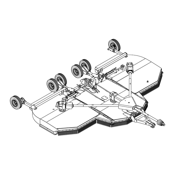
- Page 1 BATWING ® ROTARY CUTTER BW240X, BW240XQ...
- Page 2 TO THE OWNER: Read this manual before operating your Woods equipment. The information presented will prepare you to do a better and safer job. Keep this manual handy for ready reference. Require all operators to read this manual carefully and become acquainted with all adjustment and operating procedures before attempting to operate.
-
Page 3: Table Of Contents
TABLE OF CONTENTS INTRODUCTION ..........2 SPECIFICATIONS. -
Page 4: Introduction
SPECIFICATIONS BW240X / BW240XQ Cutting Height (Varies with tire selection) ..........2" - 15"... -
Page 5: Safety Video Order Form
Safety Video Order Form BE SAFE! BE ALERT! BE ALIVE! BE TRAINED Before Operating Mowers! Safety Training Does Make a Difference. ASSOCIATION OF EQUIPMENT MANUFACTURERS Free Mower Safety Video Fill out and return the order form and we will send you a FREE VHS or DVD video outlining Industrial and Agricultural Mower Safety Practices. - Page 6 DVD Format - DVD01052 Safety Video Name: ________________________________________ Phone: __________________ Address: _____________________________________ _____________________________________ _____________________________________ Mower/Cutter Model: ______________________ Serial #: ________________________ Send to: ATTENTION: DEALER SERVICES WOODS EQUIPMENT COMPANY PO BOX 1000 OREGON IL 61061-1000 6 Safety Safety Video Order Form (Rev. 2/6/2006)
-
Page 7: Safety Rules
SAFETY RULES ATTENTION! BECOME ALERT! YOUR SAFETY IS INVOLVED! TACT A PHYSICIAN IMMEDIAT ELY IF FL UID Safety is a primary concern in the design and ENTERS SKIN OR EYES. DO NOT DELAY. manufacture of our products. Unfortunately, our Never allow children or untrained persons to efforts to provide safe equipment can be wiped out by an operator’s single careless act. - Page 8 SAFETY RULES ATTENTION! BECOME ALERT! YOUR SAFETY IS INVOLVED! TRANSPORTATION (Safety Rules continued from previous page) Make sure driveline guard tether chains are Power unit must be equipped with ROPS or attached to the tractor and equipment as shown in ROPS cab and seat belt.
- Page 9 SAFETY RULES ATTENTION! BECOME ALERT! YOUR SAFETY IS INVOLVED! Watch for hidden hazards on the terrain during (Safety Rules continued from previous page) operation. Full chain or rubber shielding must be installed when operating in populated areas or other areas ...
- Page 10 SAFETY RULES ATTENTION! BECOME ALERT! YOUR SAFETY IS INVOLVED! Never perform service or maintenance with (Safety Rules continued from previous page) engine running. Never go underneath equipment (lowered to the Do not disconnect hydraulic lines until machine ground or raised) unless it is properly blocked and secured.
-
Page 11: Safety Decals
DO NOT OPERATE - PUT SHIELD ON decals causing them to peel or come off. Replacement safety decals can be ordered free 17 - PN 1004114 from your Woods dealer. To locate your nearest DANG NGER dealer, check the Dealer Locator at If shaft connection is visible, shield www.WoodsEquipment.com, or in the United States... - Page 12 SAFETY & INSTRUCTIONAL DECALS ATTENTION! BECOME ALERT! YOUR SAFETY IS INVOLVED! Replace Immediately If Damaged! 7 - PN 15503 WARNING DANGER DO NOT EXCEED PTO SPEED OF 5 - PN 15922 1000 RPM PTO speeds higher than 1000 RPM can cause equipment failure and personal injury.
- Page 13 SAFETY & INSTRUCTIONAL DECALS ATTENTION! BECOME ALERT! YOUR SAFETY IS INVOLVED! Replace Immediately If Damaged! 12 - PN 1004991 WARNING TRANSPORT LOCK AND CYLINDER REQUIREMENTS RAISED CUTTER CAN DROP AND CRUSH Cutte ers must be equipped with transport lock. SINGLE-ACTING FULL EXTENSION stan All tr...
-
Page 14: Operation
OPERATION The designed and tested safety of this machine sturdy, rough-soled work shoes and protective depends on it being operated within the limitations as equipment for eyes, hair, hands, hearing, and head; explained in this manual. Be familiar with and follow all and respirator or filter mask where appropriate. - Page 15 Hydraulic Connection Cutting Height Adjustment NOTICE 1. Inspect hydraulic hoses to ensure they are in good condition. ■ Avoid ground contact with blades. Striking ground with blades produces one of the most dam- 2. Clean the fittings before connecting them to the aging shock loads a cutter can encounter.
- Page 16 cutter drive system. Increase throttle to recommended PTO operating RPM. Be sure operator is familiar with all controls and can stop tractor and cutter quickly in an emergency. The operator should give complete, undivided attention to operating tractor and cutter. CUTTER OPERATION When beginning operation of the cutter, make sure that all persons are in a safe location.
- Page 17 Use extreme care and reduce ground speed on Always attach safety chain to tractor drawbar slopes and rough terrain. when transporting unit. Watch for hidden hazards on the terrain during Never exceed 20 mph (32.2 km/h) during trans- operation.
- Page 18 Center Section Lock-Up PRE-OPERATION CHECK LIST (OWNER'S RESPONSIBILITY) ___ Review and follow all safety rules and safety decal instructions on page 7 through page 13. ___ Check that all safety decals are installed and in good condition. Replace if damaged. ___ Check that equipment is properly and securely attached to tractor.
-
Page 19: Owner Service 19
OWNER SERVICE The information in this section is written for operators BLOCKING METHOD who possess basic mechanical skills. If you need help, To minimize the potential hazards of working under- your dealer has trained service technicians available. neath the cutter, follow these procedures: For your protection, read and follow the safety informa- ARNING tion in this manual. - Page 20 1. Driveline U-joint 10 Hours 2. Telescoping shaft 10 Hours 3. Carrier bearing block 40 Hours 4. CV body assembly 10 hours (10 pumps minimum) 5. Driveline shield 10 Hours 6. Splined yoke 10 Hours 7. Gearbox (above lower Daily line on dipstick) 8.
- Page 21 Seasonal Lubrication lock clip (12, keyhole plate (11), and shims (9 & 10). Carefully drive blade pin (7) out of crossbar. In addition to the daily recommended lubrication, a 4. Rotate crossbar and repeat for opposite blade. more extensive application is recommended season- ally.
- Page 22 Blade Sharpening SLIP CLUTCH ADJUSTMENT (FIGURE 7) The slip clutch is designed to slip so that the gearbox NOTICE and driveline are protected if the cutter strikes an ■ When sharpening blades, grind the same obstruction. amount on each blade to maintain balance. A new slip clutch or one that has been in storage over Replace blades in pairs.
- Page 23 Sand down scratches and the edges of areas of increase in air pressure and result in a tire explosion. missing paint and coat with Woods spray paint of Welding can structurally weaken or deform the wheel. matching color (purchase from your Woods dealer).
-
Page 24: Troubleshooting
TROUBLESHOOTING PROBLEM POSSIBLE CAUSE SOLUTION Does not cut Dull blades Sharpen blades. Worn or broken blades Replace blades. (Replace in pairs only.) Incorrect PTO speed Set at rated PTO speed. Ground speed too fast Reduce ground speed. Drive not functioning (blades do Check drive shaft connection. -
Page 25: Dealer Service 25
DEALER SERVICE The information in this section is written for dealer ser- Seal Replacement (Figure 12) vice personnel. The repair described here requires Recommended sealant gearbox repair special skills and tools. If your shop is not properly ® Permatex Aviation 3D Form-A-Gasket or equivalent. equipped or your mechanics are not properly trained in this type of repair, you may be time and money ahead Leakage can occur at the vertical or horizontal gaskets... - Page 26 Vertical Shaft Seal Replacement (Figure 13) 5. Remove six cap screws (23) and top cover (22) from housing. Remove gear (1) from inside 1. Disconnect and remove the rear driveline from the housing. gearbox. 6. Remove oil seal (19) from front of housing (to be 2.
- Page 27 correct diameter. Be sure not to damage the seal 0.012". Check rotational torque by hand. The lip. torque should be less than 2.2 lbs-inch. 16. Check that the gear backlash is between 0.006" 8. Press in housing so that seal is recessed. Press and 0.016".
- Page 28 SPLITTER GEARBOX REPAIR Assembly (Figure 14) 1. Clean housing, pay specific attention to areas Removal from Cutter where gaskets are installed. 2. Wash housing and all components thoroughly. 1. Disconnect remove drivelines from gearbox. 3. Select a clean work area to assemble gearbox. 2.
- Page 29 Gearbox Inspection 4. Install breather (24) in top cover. 1. Check gearbox for leaks by: plugging all holes Gearbox Installation except one, applying 4 psi of compressed air, and NOTE: Gearbox is heavy: do not attempt to move it immersing gearbox in water. Verify gearbox does without mechanical assistance.
- Page 30 CROSSBAR REMOVAL 1. It is necessary to gain access to bottom side of cutter for crossbar removal. See Blocking Method page 19. NOTE: You will need to use either the puller screw (Item 6, Figure 16) or a small hydraulic jack to remove the crossbar.
- Page 31 CROSSBAR INSTALLATION 1. Using emery cloth (220 or finer), remove surface ® rust, Loctite and foreign material from hub, splined gearbox vertical shaft, and crossbar assembly. 2. Slide crossbar assembly (8) onto splined shaft. Install washer (68) and nut (69) and align a slot with hole in splined shaft.
- Page 32 4. Place universal cross in vise as shown in Figure 22 SERVICE TIRES SAFELY and tap on yoke to remove cup. Repeat Step 3 for Used Aircraft Tires (Figure 23) final removal. Drive remaining cup out with a drift and hammer. WARNING Do not attempt to mount a tire unless you have the proper equipment and experience to perform the job.
-
Page 33: Assembly Instructions
(12), carriage bolts (59) and lock nuts (32). Clamps Assembly of this cutter is the responsibility of the are used at the both front and at the rear of the WOODS dealer. It should be delivered to the owner deck. completely assembled, lubricated and adjusted for nor- 4. - Page 34 3. Tighten nuts until there is approximately 1 inches 6. Install bushing (24), elbow, (23) and hose (22) to the base end of cylinder (3). thread exposed past nuts. Further adjustment will be need once cutter is attached to NOTE: Make sure a breather fitting is installed in tractor drawbar.
- Page 35 Install Spring Wheel Arms Install Tongue 1. Slide right spring wheel arm assembly (14) over 1. Attach tongue (22) to center section using two center wheel yoke tube and secure into position tongue pivot pins (31). Secure pivot pins to mast using four cap screw (28) and flanged lock nut plates using carriage bolts (67) and lock nuts (53).
- Page 36 Install 3-Joint Drive (540 RPM Only) 4. Secure with bolt and nut supplied with drive. 5. Secure driveline carrier bearing to H-frame with Before installing cutter input driveline to gearbox, check cap screw (54), washer (51) and a flanged lock nut the tag wired to the driveline and the tag wired to the (53).
- Page 37 Install CV Drive (Optional) 4. Repeat procedure of opposite wing. Before installing cutter input driveline to gearbox, check the tag wired to the driveline and the tag wired to the input shaft of gearbox. Ensure the tag rpm speeds match the rpm speed decal on front of cutter. After con- firming all speeds match, remove and discard tags and then complete driveline assembly.
- Page 38 5. Hydraulic cylinder 18. 1" x 4.58" Clevis pin 19. 1" x 5.08" Clevis pin 20. Wing transport lock 23. 1/4 NPT x 1/4 NPT Elbow, restricted 24. 1/2 NPT x 1/4 NPT Reducer bushing 25. 1/4 NPT x 1/4 NPT x 264" Hose 29.
- Page 39 Install Wing Wheel Yoke Adjustment Link Install Wing Driveline 1. Remove knob on top of clutch shield (3) and raise CAUTION shield. Use a suitable lifting device of sufficient capac- 2. Slide clutch of driveline (4) over wing gearbox shaft ity.
- Page 40 OPTIONAL EQUIPMENT Install Tandem Wheel Assembly (Wing) 1. Attach wing wheel yoke (2) to the wing using pivot Install Tandem Wheel Assembly (Center) pins (31). See Figure 33 for pin and hardware 1. Slide spring wheel arm assembly (1) over right side installation.
- Page 41 INSTALL CHAIN OR BELT SHIELDING condition. It is possible for objects to ricochet and escape, traveling as much as 300 feet (92 m). ANGER Install chain and rubber shields with hardware as Full chain shielding must be installed when shown.
- Page 42 4-Link 6-Link 1. Front wing chain plate, inner 4. Rear wing chain plate 14. 1/2 NC x 1-1/2 Carriage bolt 2. Front wing chain plate, center 13. 5/16 Chain - 4-link 15. 1/2 NC Flange lock nut 3. Front wing chain plate, outer 12.
- Page 43 1. Front right wing belt shield plate, outer 5. Rear right wing belt shield plate, inner 2. Front wing belt shield plate, inner 6. Link .25 x 1.00 x 27.00 3. Front wing belt shield plate, center 7. Rubber belt, .25 x 8.50 x 27.25 4.
-
Page 44: Dealer Check List
DEALER CHECK LISTS PRE-DELIVERY CHECK LIST ___ Show customer how to determine the turning lim- its of the CV PTO driveline. (DEALER’S RESPONSIBILITY) ___ Show customer the safe, proper procedures to be Inspect the equipment thoroughly after assembly to used when mounting, dismounting, and storing ensure it is set up properly before delivering it to the equipment. - Page 45 PARTS INDEX BATWING ® Rotary Cutter BW240X, BW240XQ MAIN FRAME ASSEMBLY (FRONT SECTION) ............46-47 (REAR SECTION) ............48-49 WING ASSEMBLY ......................50-51 GEARBOX ASSEMBLY WING & CENTER ............52-53 SPLITTER ................. 54 DRIVE ASSEMBLY CENTER DECK ..............55 FRONT - 3-JOINT (EQUAL ANGLE) ......... 56 REAR - 3-JOINT (EQUAL ANGLE)........
- Page 46 MAIN FRAME ASSEMBLY (FRONT SECTION) (Rev. 9/1/2016) 46 Parts MAN0725 (10/3/2008)
- Page 47 MAIN FRAME ASSEMBLY (FRONT SECTION) R E F PART DESCRIPTION R EF PART DESCRIPTION 300451 * 5/8 NC x 1-1/4 HHCS GR5 8825KT 1 Blade kit, CCW 57817 5/8 SAE Hardened flat washer ----- 1 Gearbox (see page 52) 902 2* 5/8 NC x 2 HHCS GR5 1027297 1 Driveline complete, 1340, 1.75-20 12.6 10635 5/8 x 1-3/4 x 14 GA Cup washer...
- Page 48 MAIN FRAME ASSEMBLY (REAR SECTION) 48 Parts MAN0725 (10/3/2008)
- Page 49 MAIN FRAME ASSEMBLY (REAR SECTION) R EF PART DESCRIPTION R E F PART DESCRIPTION 11893 1 1/2 x 1/4 Pipe reducer bushing 1027070 1 Center wheel yoke 1024122 1 NC x 13 HHCS GR5 57050 1 Access hole cover 34279 * 1 NC Lock nut 10475 1 Hydraulic cylinder 3-1/2 (see page 70) 11920 1 x 1-7/8 x 1/4 Washer...
- Page 50 WING ASSEMBLY Right Wing Shown Rev. (9/1/2016) 50 Parts MAN0725 (10/3/2008)
- Page 51 WING ASSEMBLY R E F PART DESCRIPTION R EF PART DESCRIPTION 8825KT 1 Blade kit, CCW (Right wing) - or - 34279 * 1 NC Lock nut 8820KT 1 Blade kit, CW (Left wing) 11920 1 x 1-7/8 x 1/4 Washer ----- 1 Gearbox (see page 52) 15087 1 NC x 9 HHCS GR5...
- Page 52 WING & CENTER GEARBOX ASSEMBLY 52 Parts MAN0725 (10/3/2008)
- Page 53 WING & CENTER GEARBOX ASSEMBLY 540 RPM 1000 RPM Left Right Left Right DESCRIPTION Wing Center Wing Wing Center Wing 1029696 58806 1029695 1029696 1029697 1029695 Complete gearbox 1025865 57316 1025865 1025865 57358 1025865 Gear crown NS Gearbox housing 57319 57319 57319 57319...
- Page 54 SPLITTER GEARBOX ASSEMBLY PART PART DESCRIPTION 540 RPM 1000 RPM 1029698 1029699 Complete splitter gearbox 21542 21542 24 10 mm Lock washer 307201 307201 24 M10-1.5 x 30 HHCS 1019613 1019613 Input cap 1019575 1019575 Input shaft 1019589 1019589 Input oil seal 1019587 1019587 Bearing assembly (cup and cone)
- Page 55 CENTER DECK DRIVE ASSEMBLY PART DESCRIPTION PART DESCRIPTION 1027297 Complete center drive assembly 57434 Thrust plate 1004961 Yoke, 1-3/4, 20 spline 57439 Belleville spring plate Cross & bearing kit 57259 M10 x 1.5P x 55 mm Cap screw 8.8 40576 Inboard yoke 57260 M10 x 1.5P Hex lock nut...
- Page 56 FRONT 3-JOINT DRIVE ASSEMBLY (EQUAL ANGLE) 540 ONLY PART DESCRIPTION REF PART DESCRIPTION 40728 Inner shield 57282 Complete 540 RPM (6 spline) 40766 Bearing ring SC25 40563 Yoke 1-3/8 - 6 spline (540 RPM) 40777 Anti-rotation chain 40566 Cross & bearing 40778 Screw 40751...
- Page 57 REAR 3-JOINT DRIVE ASSEMBLY (EQUAL ANGLE) PART DESCRIPTION PART DESCRIPTION 1004932 Complete rear drive assembly 40777 Anti-rotation chain 1004957 Yoke, 1-3/4, 20 spline 40767 Support bearing 40566 Cross and bearing 18864 Decal, danger rotating driveline 1003471 Inboard yoke 33347 Decal, danger guard missing 1004958 Inner profile 1004960...
- Page 58 TYPE A - 540 RPM FRONT CV DRIVE REF PART DESCRIPTION REF PART DESCRIPTION 1021103 Complete CV drive (540 RPM) 1021315 CV shield inner (540 RPM) 19851 Slide lock repair kit 33347 † Decal, danger guard missing 58774 Yoke QD CV 1.375 - 6 (540 RPM) (see page 13) 58759 CV U-Joint repair kit Cat 6 55E...
- Page 59 TYPE B - 540 RPM FRONT CV DRIVE REF PART DESCRIPTION REF PART DESCRIPTION 1021103 Complete CV drive (540 RPM) 1021315 CV shield inner (540 RPM) 19851 Slide lock repair kit 33347 † Decal, danger guard missing 1033103 Yoke QD CV 1.375 - 6 (540 RPM) (see page 13) 1033107 CV U-Joint repair kit Cat 6 55E...
- Page 60 TYPE A - 1000 RPM FRONT CV DRIVE 1000 RPM 1-3/8 21-Splined 1000 RPM 1-3/4 20-Splined REF PART DESCRIPTION REF PART DESCRIPTION 1021104 Complete CV drive assembly 1021105 Complete CV drive assembly 19851 Slide lock repair kit 19837 Slide lock repair kit 58770 Yoke QD CV 1.375 - 21 58758...
- Page 61 TYPE B - 1000 RPM FRONT CV DRIVE 1000 RPM 1-3/8 21-Splined 1000 RPM 1-3/4 20-Splined REF PART DESCRIPTION REF PART DESCRIPTION 1021104 Complete CV drive assembly 1021105 Complete CV drive assembly 19851 Slide lock repair kit 19837 Slide lock repair kit 1033104 Yoke QD CV 1.375 - 21 1033105...
- Page 62 WING DRIVE ASSEMBLY R E F PART DESCRIPTION R E F PART DESCRIPTION 1027296 Complete wing drive assembly 40779 1 Grease fitting 1019111 1 Yoke 1-3/4 20 special 44677 1 Inboard yoke S5 38352 2 Cross and bearing kit 2400 1019114 1 Clutch (includes 18 thru 24, 27,28) 90317352 1 Inboard yoke S4 1027217 1 Flange Yoke...
- Page 63 5-BOLT WHEEL & TIRE ASSEMBLY PART DESCRIPTION PART DESCRIPTION 1017050 1 Heavy hub assembly 16 1039976F 25 x 8 - 14 Severe duty ag tire, (includes items 1 through 15) rim & hardware, foam filled - 5 bolt 1017034 1 Heavy wheel hub with cups 1017030 29 x 9 x 15 Aircraft tire, (includes items 6,7,14)
- Page 64 RUBBER SHIELDING - CENTER SECTION (STANDARD) R EF PART DESCRIPTION 1027164 1 Front center belt shield plate 1027166 1 Front right belt shield plate 1027167 1 Front left belt shield plate 1027176 4 Bent link .25 x 1.61 x 12.00 1027284 2 Rubber shield .25 x 8.50 x 44.74 1027289 2 Rubber shield .25 x 8.88 x 32.50 6697 * 3/8 NC x 1 Carriage bolt GR5...
- Page 65 RUBBER SHIELDING - WING (STANDARD) R E F PART DESCRIPTION R EF PART DESCRIPTION 1027168 1 Front right wing belt shield plate, outer 1027286 1 Rubber shield .25 x 8.50 x 43.50 - or - 1027287 1 Rubber shield .25 x 8.50 x 36.05 1027169 1 Front left wing belt shield plate, outer 1027288 1 Rubber shield .25 x 8.88 x 54.50 1027171 1 Front wing belt shield plate, inner...
- Page 66 CHAIN SHIELDING - CENTER SECTION (OPTIONAL) SINGLE ROW DOUBLE ROW R E F PART DESCRIPTION R E F PART DESCRIPTION 1027131 1 Front center chain plate 1029881 1 Front center chain plate 1027132 1 Front right chain plate 1029882 1 Front right chain plate 1027133 1 Front left chain plate 1029883 1 Front left chain plate 1027141 2 Rear chain plate...
- Page 67 CHAIN SHIELDING - WING (OPTIONAL) SINGLE ROW DOUBLE ROW R E F PART DESCRIPTION R EF PART DESCRIPTION 1027134 1 Front wing chain plate, inner 1029885 1 Front wing chain plate, inner 1027140 1 Front wing chain plate, center 1029884 1 Front wing chain plate, center 1027136 1 Front right wing chain plate, outer - or - 1029886 1 Front right wing chain plate, outer - or - 1027137 1 Front left wing chain plate, outer...
- Page 68 TANDEM AXLE WHEEL YOKE (OPTIONAL) R E F PART DESCRIPTION R E F PART DESCRIPTION 1024109 2 Wheel yoke arm, spring 11920 * Washer, 1 x 1-7/8 x 1/4 1027080 1 Wheel yoke, spring right 19710 2 Spring/cmp 3.25 .69. 9.52200 (for right wing) -or- 1023170 2 Lower spring arm, tandem 1027081 1 Wheel yoke, spring left...
- Page 69 LIGHT KIT ASSEMBLY PART DESCRIPTION PART DESCRIPTION 1036885 1 LED Light kit, complete 78059 Clamp, .50 dia steel cushion 1036887 1 Wire harness, 16 foot, main 78162 * Screw, #10 NC x 7/16 self-tapping 1040277 1 AG Enhancer module 10378 * 1/4 NC x 1 HHCS, GR5 1040279 1 Wire harness, rear, 2 pieces 70065 *...
- Page 70 HYDRAULIC CYLINDERS * NOTE CYLINDER, 52234, HAS M16 TIE ROD NUTS (24MM ACROSS FLAT) USING KIT 23540 3-1/2 x 8 3-1/2 x 16 PART PART DESCRIPTION 10475 52234 Complete cylinder 23540 23540 Seal repair kit (includes items 2A - 2G) †...
- Page 71 HYDRAULIC CYLINDERS * NOTE CYLINDER, 597276, HAS M14 TIE ROD NUTS (21MM ACROSS FLAT) USING KIT 600251 3.5X1.25ø ROD PART DESCRIPTION COMPLETE CYLINDER 600251 SEAL KIT (INCLUDES ITEMS 2A-2F) † CAP O-RING † PISTON SEAL † ROD O-RING † CAP SEAL †...
- Page 72 HYDRAULIC CYLINDER STROKE CONTROL KIT PART DESCRIPTION 24098 Stroke control set for 1-1/4" cylinder rod (contains items 2 - 5) – – – – 1-1/2" Segment – – – – 1-1/4" Segment – – – – 1" Segment – – – – 3/4"...
- Page 73 WINCH KIT (OPTIONAL) Winch Kit Operation REF PART DESCRIPTION 1. Move cutter so wing is on the up slope of a ditch 1019456 Winch kit, complete to aid in wing lift with the winch. 52478 Idler bracket 2. Unwind cable and remove roller (2). 6696 Chain idler casting Clevis pin, 1/2 x 2...
-
Page 74: Bolt Torque Chart
BOLT TORQUE CHART Always tighten hardware to these values unless a different torque value or tightening procedure is listed for a specific application. Fasteners must always be replaced with the same grade as specified in the manual parts list. Always use the proper tool for tightening hardware: SAE for SAE hardware and Metric for metric hardware. Make sure fastener threads are clean and you start thread engagement properly. - Page 75 BOLT SIZE CHART NOTE: Chart shows bolt thread sizes and corresponding head (wrench) sizes for standard SAE and metric bolts. SAE Bolt Thread Sizes 5/16 Metric Bolt Thread Sizes 10MM 12MM 14MM 16MM 18MM ABBREVIATIONS AG...............Agriculture MPa ............Mega Pascal ASABE ....American Society of Agricultural & N ..............
-
Page 76: Index
INDEX ADJUSTMENTS Replacement Parts OPERATION Cutting Height Slip Clutch Connecting Cutter to Tractor ASSEMBLY Cutting Height Adjustment CV Driveline Turning Limits Dealer Set-Up Instructions Hydraulic Connection Fill Gearboxes Interference Check Optional Equipment Cutter Operation Mowing Tips DEALER CHECK LIST Shredding Check Lists Pre-Operation Check List (Owner’s Responsibility) Delivery (Dealer’s Responsibility) - Page 77 The limited warranty covers any defects in the material and/or workmanship. Following the proper, recommended installation by an authorized Woods Dealer and normal use of a Woods mounting and backhoe or loader, if a tractor incurs damage resulting from the attachment, Woods will cover the existing tractor warranty in the event the manufacturer voids its tractor warranty because of the attachment.
- Page 78 Woods logo are trademarks of Woods Equipment Company. All other trademarks, trade names, or service marks not owned by Woods Equipment Company that appear in this manual are the property of their respective companies or mark holders. Specifications subject to change without notice.
Need help?
Do you have a question about the BW240X and is the answer not in the manual?
Questions and answers