Table of Contents
Advertisement
Quick Links
Advertisement
Table of Contents

Related Manuals for Innova DS200


Summary of Contents for Innova DS200
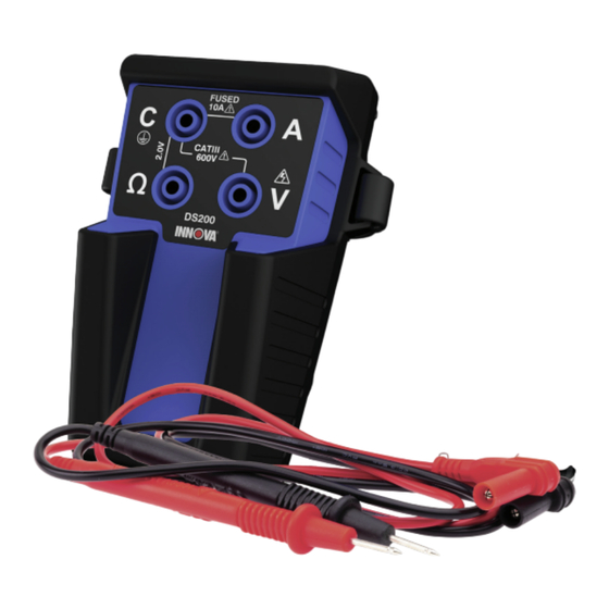
- Page 1 DS200 Channel Graphing Multimeter...
-
Page 2: Package Contents
INTRODUCTION The DS200 Channel Graphing Multimeter is an automotive industry compact 2 channel Bluetooth graphing multimeter connected to a smart device application that allows for both the initial information to be read and received, but also is opening the gateway into the future of data intelligence and interpretation. -
Page 3: Safety Information
Safety Information SAFETY INFORMATION WARNING: Denotes a potentially hazardous situation that may result in injury or death CAUTION: Denotes a potentially hazardous situation that may result in damage to the meter NOTE: Denotes a situation that may result in degraded or incorrect measurement §... - Page 4 Introduction TABLE 2 TERMINALS Terminal Description Common terminal for all measurements Input terminal for measuring currents to 10A RMS (AC and DC) Input terminal for measuring voltages to 600V RMS (AC and DC) Input terminal for measuring resistance, diode drop and voltages up to 1.2V...
-
Page 5: Measuring Voltage
Make sure the probe tips are fully in contact with the circuit before assuming the circuit is safe. Two of the DS200 Multimeter’s input terminals are capable of making basic voltage measurements: The V terminal can measure up to 600V RMS and is intended for traditional AC and DC voltage measurements. - Page 6 Basic Measurement Instructions Measuring Current with the Internal Current Shunt MEASURING CURRENT WITH THE INTERNAL CURRENT SHUNT WARNING: Exercise care when connecting in series with a circuit, especially those containing motor(s). Sudden disconnects may create higher than expected voltages due to inductive kick. WARNING: Perform a Fuse Check before measuring currents with the internal current shunt.
- Page 7 Basic Measurement Instructions Measuring Current with an External Current Shunt MEASURING CURRENT WITH AN EXTERNAL CURRENT SHUNT NOTE: This function may not be compatible with all scan tools. Please verify its compatibility before using it. WARNING: This measurement mode is capable of measuring currents of many orders of magnitude larger than is typically possible with a handheld meter.
-
Page 8: Measuring Resistance
Basic Measurement Instructions Measuring Resistance MEASURING RESISTANCE NOTE: Do not measure resistance on a live circuit. Doing so will result in incorrect readings and may engage the internal protection circuitry. Should this occur, wait 5 minutes before taking further measurements. §... -
Page 9: Diode Testing
Basic Measurement Instructions Diode Testing DIODE TESTING NOTE: Do not use the diode test functionality while connected to a live circuit. Doing so will result in incorrect readings and may engage the internal protection circuitry. Should this occur, wait 5 minutes before taking further measurements. §... - Page 10 Basic Measurement Instructions Using a BNC Adaptor USING A BNC ADAPTOR NOTE: This function may not be compatible with all scan tools. Please verify its compatibility before using it. The 4 terminals are arranged with 0.75” spacing to allow for use of a standard BNC adapter. Measurements using the A or Ω terminals can be used with the C terminal as usual.
-
Page 11: Two Channel Measurements
MEASURING SMALL RESISTANCES / CALIBRATING A CURRENT SHUNT The DS200 Multimeter can be used to measure small resistances in a live circuit. The meter simultaneously measures the current and the corresponding voltage with the precision voltage channel (Ω), and then finds the slope to calculate resistance. -
Page 12: Power Factor
Two Channel Measurements Power Factor POWER FACTOR Power Factor compares apparent power and actual power and is a measure of how effectively a load uses available power. This measurement requires voltage and current measurements. Current measurement can be done with either internal or external current shunt mode. -
Page 13: Maintenance
Maintenance Opening Up Your DS200 Multimeter OPENING UP YOUR DS200 MULTIMETER WARNING: To avoid electric shock, disconnect test leads from the meter before opening the meter. Disconnect all test leads. Unscrew both retaining screws from the bottom of the case with a Phillips head screwdriver. - Page 14 Maintenance Closing your Innova Multimeter CLOSING YOUR INNOVA MULTIMETER WARNING: Risk of electrical shock. Do not operate the meter while partially disassembled. Place the PCB in the bottom enclosure half. Use the “J” shaped fin for alignment with the corresponding cut-out in the PCB.
-
Page 15: Battery Replacement
Observe the battery polarity indication on the circuit board. Insert 2 new AA 1.5V batteries as shown on the circuit board. If you have inserted the batteries with the correct polarity, the Innova Multimeter’s LED will blink slowly several times before turning off. -
Page 16: Fuse Replacement
Perform a resistance measurement with the C and Ω terminals connected. If the resistance measured is greater than 0.5Ω, replace the fuse* * The resistance mode on the Innova Multimeter is not accurate below 1Ω. The actual resistance of the fuse should be 20mΩ. -
Page 17: Replacing The Sd Card
Replacing the SD Card REPLACING THE SD CARD NOTE: This function may not be compatible with all scan tools. Please verify its compatibility before using it. WARNING: To avoid electric shock, disconnect all leads from the meter. NOTE: Only use FAT32 formatted SD cards up to 32 gigabytes. Larger SD cards or cards formatted differently cannot be written to memory. Open the meter per the directions above. - Page 18 Resetting Your Innova Multimeter RESETTING YOUR INNOVA MULTIMETER WARNING: To avoid electric shock, disconnect all leads from the meter. Open the meter per the directions above. Press and hold the button shown for 5 seconds. Close the meter per the directions above.
-
Page 19: General Specifications
Accuracy is specified for 1 year after calibration within 18 to 28C. Accuracies listed are for single-channel measurements only. Multi- channel measurements may degrade accuracy. For extended specifications visit www.Innova.com. All AC ranges are RMS assuming a pure sinusoid (crest factor √ ). Derate ranges linearly with increasing crest factor. - Page 20 General Specifications Voltage, Terminal V: Current, Terminal A Accuracy DC Range AC Range Resolution Noise Floor Accuracy (%+count) DC Range AC Range Resolution Noise Floor (%+counts) 600 V 275 µV 9 mV 0.5 + 20 10 A 3.8 µA 120 µA 0.5 + 50 600 V 430 V...
- Page 21 General Specifications Voltage, Auxiliary Terminal: Accuracy Terminal Surge Protection Input Impedance DC Range AC Range Resolution Noise Floor (%+count) >100MΩ <200pF 1000 mV 700 mV 300 nV 10 µV 0.5 + 20 800V >100MΩ <200pF Ω 680 mV 475 mV 150 nV 5 µV 0.5 + 20...
- Page 22 This device may not cause harmful interference. This device must accept any interference received, including interference that may cause undesired operation. Changes and Modifications not expressly approved by Innova IEC can void your authority to operate this equipment under Federal Communications Commission’s rules.
- Page 23 Innova Electronics Corp. 17352 Von Karman Ave. Irvine, CA 92614 MRP# 93-1180 Rev. A Made In Taiwan Copyright © 2023 IEC. All Rights Reserved.
Need help?
Do you have a question about the DS200 and is the answer not in the manual?
Questions and answers