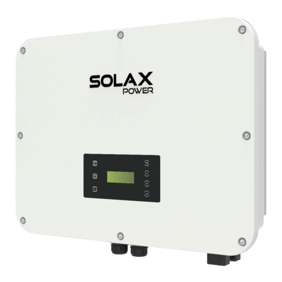
SolaX Power X3-ULTRA User Manual
Hide thumbs
Also See for X3-ULTRA:
- User manual (184 pages) ,
- Installation manual (91 pages) ,
- User manual (199 pages)
Summary of Contents for SolaX Power X3-ULTRA
- Page 1 X3-ULTRA 15 kW / 19.9 kW / 20 kW / 25 kW / 30 kW User Manual Version 2.0 www.solaxpower.com eManual in the QR code or at http:// kb.solaxpower.com/...
- Page 3 No part of this manual may be reproduced, transmitted, transcribed, stored in a retrieval system, or translated into any language or computer language, in any form or by any means without the prior written permission of SolaX Power Technology (Zhejiang) Co., Ltd. Trademarks and other symbol or design (brand name, logo) that distinguishes the products or services offered by SolaX has been trademark protected.
- Page 4 About This Manual Scope of Validity This manual is an integral part of X3-ULTRA series inverter. It describes the installation, electrical connection, commissioning, maintenance and troubleshooting of the product. Please read it carefully before operating. This manual is valid for the following inverter models: •...
- Page 5 Conventions The symbols that may be found in this manual are defined as follows. Symbol Description Indicates a hazardous situation which, if not avoided, DANGER will result in death or serious injury. Indicates a hazardous situation which, if not avoided, WARNING could result in death or serious injury.
-
Page 6: Table Of Contents
Table of Contents Safety ......................1 1.1 General Safety ........................1 1.2 Safety Instructions of PV, Inverter and Grid ...............1 1.2.1 Safety Instructions of PV ..................2 1.2.2 Safety Instructions of Inverter ................2 1.2.3 Safety Instructions of Utility Grid ..............3 Product Overview ..................4 2.1 System Description ......................4 2.2 Appearance .........................4 2.3 Supported Power Grid .....................5... - Page 7 Unpacking and Inspection ..............29 6.1 Unpacking ..........................29 6.2 Scope of Delivery.......................30 Mechanical Installation ................32 7.1 Dimensions for mounting ....................33 7.2 Installation procedures.....................34 Electrical Connection ................37 8.1 Terminals of Inverter ......................37 8.2 PE Connection ........................38 8.3 AC Connection ........................41 8.4 PV Connection ........................45 8.5 Battery Power Cable Connection .................49 8.6 COM 1 Communication Connection ................56 8.6.1 Pin Assignment of COM 1 Teriminal ...............56...
- Page 8 10.8 About .............................108 Operation on SolaX Cloud App .............110 11.1 Introduction of SolaX Cloud App ..................110 11.2 Downloading and installing App ...................110 11.2.1 Downloading and installing App ..............110 11.3 Operation Guide on SolaXCloud Web ................111 Troubleshooting and Maintenance ............112 12.1 Power off ..........................112 12.2 Troubleshooting .........................112 12.3 Maintenance ........................121 12.3.1 Maintenance routines ..................121...
-
Page 9: Safety
Safety General Safety The series inverter has been meticulously designed and thoroughly tested to comply with the relevant state and international safety standards. Nevertheless, like all electrical and electronic equipment, safety precautions must be observed and followed during the installation of the inverter to minimize the risk of personal injury and ensure a safe installation. -
Page 10: Safety Instructions Of Pv
Safety 1.2.1 Safety Instructions of PV DANGER! Potential risk of lethal electrical shock associated with the photovoltaic (PV) system • Exposure to sunlight can result in the generation of high DC voltage by PV modules, which can lead to electric shock causing severe injuries or even death. •... -
Page 11: Safety Instructions Of Utility Grid
Safety WARNING! • During operation, avoid touching any parts of the inverter other than the DC switch and LCD panel. • Never connect or disconnect the AC and DC connector while the inverter is running. • Prior to conducting any maintenance, turn off the AC and DC power and disconnect them from the inverter. -
Page 12: Product Overview
Product Overview System Description The X3-ULTRA series is the energy storage inverter that supports grid connection of photovoltaic system. It greatly meets the requirements of solar-powered roofs and supports various intelligent solutions such as load management, wireless metering, dual battery terminals, microgrids, etc., to achieve efficient and economical energy utilization. -
Page 13: Supported Power Grid
Product Overview Supported Power Grid There are different ways of wiring for different grid systems. TT / TN-S / TN-C-S are shown as below: 400 V 400 V 400 V L1 L2 L3 Inverter 1.L-N: 230 V; L-L: 400 V 2.L-N: 220 V; L-L: 380 V Figure 2-2 Supported power grid-TT 400 V 400 V... -
Page 14: Symbols On The Label And Inverter
Product Overview Symbols on the Label and Inverter Table 2-2 Description of symbols Symbol Description CE mark. The inverter complies with the requirements of the applicable CE guidelines. TUV certified. UKCA mark. The inverter complies with the requirements of the applicable UKCA guidelines. -
Page 15: Working Principle
BAT 1 BAT1+ BAT 1 Circuit BAT1- Filter AC SPD BAT2 BAT2+ BAT 2 Circuit BAT2- Filter Figure 2-5 Circuit Diagram for X3-ULTRA series inverter NOTICE! • MPPT 3 is available for 15 KP, 25 kW and 30 kW inverter.


Need help?
Do you have a question about the X3-ULTRA and is the answer not in the manual?
Questions and answers