
Related Manuals for INNO A870 OTDR


Summary of Contents for INNO A870 OTDR
- Page 1 OTDR User Manual Please read this Manual carefully before operation Please keep this Manual along with the device Ver V1.00...
-
Page 2: Table Of Contents
Content VIEW 5 Pro Preface Chapter 1 Overview Introduction ..................................Basic functions..................................Standard configuration................................. Power supply..................................Dimensions and weight ............................... Environmental conditions ..............................Chapter 2 Installation Safety reminder and precautionary measures........................Safety warnings for operation............................. Transportation and storage..............................Appearance overview................................Charging method.................................. - Page 3 4.18 Return key....................................4.19 Main menu key ..................................Chapter 5 SOLA (Purchase) 5.1 Overview....................................5.2 SOLA operation..................................Settings ....................................5.4 Save/open....................................5.5 Management................................... 5.7 Save as....................................Chapter 6 Light Source 6.1 Overview....................................6.2 Visual light source operation............................... 6.3 Stable light source operation............................... Chapter 7 File Management 7.1 Overview....................................
-
Page 4: Preface
VIEW 5 Pro Preface Safety Symbols In order to prevent personal injury and loss due to the misoperation of the instrument, INNO Instrument uses the following safety signs to indicate relevant safety information. Before using the instrument, be sure to clearly understand the meaning of these signs. Some or all of the signs may not be found on the instrument. In addition, safety signs of the device may not be marked in the illustrations of this manual. Safety Signs used in the Manual Sign Description This sign indicates that this is a very dangerous operation, and improper operation will lead to Hazard serious injury and even death. This sign indicates that this is a relatively dangerous operation, and improper operation will Warning lead to serious injury and even death. This sign indicates that this is a relatively dangerous operation, or has a certain harm and im- Caution proper operation due to carelessness will lead to mild or serious injury and loss. Safety Signs used in the Manual and Machine: The following safety signs are marked in the device, near the operation position, or in the manual to provide relevant safety information and prompt the user to operate with care. Before using the instrument, be sure that you have clearly understood the meaning of these signs and take necessary precautionary measures. Sign Description This sign indicates a forbidden operation. This circle with a slash is labeled on the operation position or near it. This sign means that you must be careful when performing a certain operation. This circle sign is labeled on the operation position or near it. This sign indicates a warning and caution. Relevant content appears inside the triangle or near This sign indicates an explanation. Relevant content is listed in the box These signs indicate that the labeled components should be recycled. - Page 5 Laser Safety Labels Electrical Safety In order to reduce damage to instrument and injury even death of human body, the following warnings are given: • Do not use if the instrument or the external charger was damaged or ruptured • Only the external power adapter provided by our company can be used. For other external power adapters, we cannot guarantee their performance and safety • Do not use the power adapter outdoors or in humid places • e sure that the external input voltage is within the allowable range Precautions Caution Replace internal memory battery: This instrument uses a lithium battery as the power supply. If it exceeds the maximum service life and needs to be replaced, please contact specialized personnel for replacement. External memory: This device uses USB and SD card memory as external memory to save data INNO Instrument (China) Inc. is not responsible for data loss...
-
Page 6: Chapter 1 Overview
A870 optical time domain reflectometer (OTDR) shortens the time for installation, debugging and fiber spacing maintenance through adopting high performance hardware and convenient software. This chapter will describe the features and basic operations of the A870 OTDR test unit. 1.2 Basic function The main function of A870 is for fiber fault diagnosis, especially aiming at FTTH applications. -
Page 7: Standard Configuration
Light Source LThe light source function of A870 provides two types of light sources, i.e.1310/1500nm, and is equipped with multiple signal modes to meet various demands in actual application. 1.3 Standard Configuration • Color TFT LCD • AC adapter/charger, power cord •... -
Page 8: Chapter 2 Installation
VIEW 5 Pro Chapter 2 Installation 2.1 Safety reminder and precautionary measures It is very important to keep in mind that A870 is designed for fiber testing, not for any other purpose. OTDR is a high precision instrument and should be carried with great care. Therefore, please always observe the following safety rules and general specifications when using and carrying the A870. -
Page 9: Appearance Overview
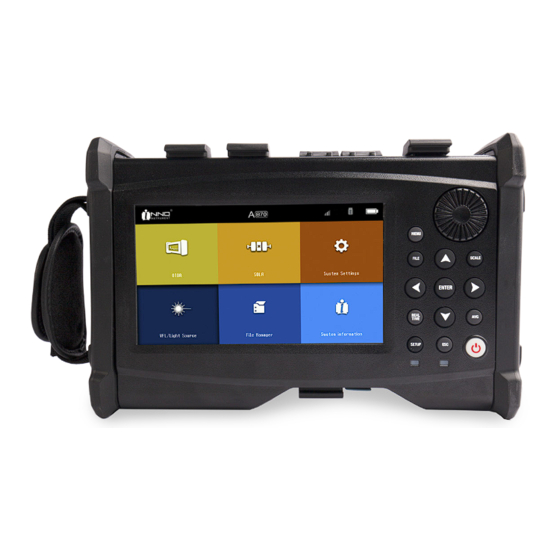
2.4 Appearance overview SMF port DC power port USB port VFL port Rotary knob Menu key OK key ON/OFF key Front Panel Description of keys Power Supply Turn on and off the device REALTIME OTDR Interface: start and stop real-time measurement Average measurement Back MENU Main menu ENTER Confirm Rotary knob OTDR interface: position the cursor precisely Left key Universal mode: move the cursor to left side in text box OTDR interface: horizontally shrink part of the curve to display a larger scope of the curve Right key Universal mode: move the cursor to right side in text box Direction keys: OTDR interface: horizontally amplify part of the curve for detailed observation Up key Up / Down / Left / Right Universal mode: move the cursor to higher level option in the pop-up menu OTDR interface: vertically amplify part of the curve to display a larger scope of the curve Down key... -
Page 10: Charging Method
VIEW 5 Pro The upper connect panel Port description DC power connector Connect the adapter Test port A870 testing interface is suitable for OTDR module function and light source module function of A870 device VFL port Visual light source port USB port Connect USB storage device Back panel 2.5 Charging method Remaining battery capacity can be checked according to the battery status when A870 is powered on. -
Page 11: Test Port
2.6 Test port The measurement port of A870 is located on the upper panel of the host. There will be 1 or 2 measurement ports depending on the type of A870. The measurement port connected to optical fiber depends on the testing application and measured wavelength. - Page 12 VIEW 5 Pro Connect VFL The 2.5mm universal connection adapter is configured to the visual light source (VFL) and it can be connected with multiple optical fiber connectors. Note : Visual light source (VFL) is optional and may not be installed on some devices. Steps for connecting the visual light source: 1.
-
Page 13: Chapter 3 Basic Operation
Chapter 3 Basic Operation 3.1 Power on/off Power on: Press the power key, the name of the device will appear on A870 screen, and then the boot screen of INNO Instrument will appear. Later the following main menu screen will appear. Power off: Press and hold the power key until the screen and indicator light turn off: Note: In any situation, you can press the power key continuously for more than 10 seconds for forced shutdown. -
Page 14: File Copy
VIEW 5 Pro 3.4 File copy As shown in the following figure, plug in the external storage device, view the path of the external storage device in "file management", and then execute operations of "copy", "paste", "delete", "rename", "send to USB", "new folder", "remove device"... -
Page 15: Chapter 4 Otdr Test
Chapter 4 OTDR Test 1. Move waveform key 12. Curve information 2. Partial amplification key 13. Start / stop key 3. "1:1" waveform reset key 14. Save key 4. Shortcut key for waveform horizontal amplification 15. OTDR setup key 5. Shortcut key for waveform horizontal shrink 16. Run report key 6. Coarse / fine adjustment key 17. Save as key 7. Full screen display key 18. Next curve key 8. Wavelength selection 19. Main menu key 9. OTDR 20. -
Page 16: Partial Amplification Key
VIEW 5 Pro 4.2 Partial amplification key Click the "Partial amplification" key in the figure, and then click the screen up, down, left and right to drag the selected area. The area will be amplified and displayed, and the amplified part will be marked in the "Curve waveform display small interface". -
Page 17: Waveform Horizontal Shrink Key
Figure 2 4.5 Waveform horizontal shrink key Click the "Waveform horizontal shrink" key in the figure to shrink the waveform. (Figure 1) is the effect before shrinking and (Figure 2) is the effect after shrinking. Horizontal shrink key Figure 1 Figure 2... -
Page 18: Coarse/Fine Adjustment Key
VIEW 5 Pro 4.6 Coarse / fine adjustment key Click the "Coarse/fine adjustment" key in the figure; when the double arrows are separated, the rotary knob adjustment cursor will move rapidly, as shown in the following figure: Cursor adjustment key When the double arrows are separated, the rotary knob adjustment cursor will move rapidly. As shown in the figure: 4.7 Full screen display key Click the "Full screen display"... -
Page 19: Measurement Setting
Figure 2 4.8 Measurement setting As shown in the figure, the "wavelength", "distance range", "pulse width" and "average time" can be set in the "measurement setting" interface. Wavelength selection Setting of measurement parameters The first is the wavelength, and the back check box is used to select the measurement wavelength. One, or both must be selected. -
Page 20: Otdr Key
VIEW 5 Pro 4.9 OTDR key As shown in the figure, enter the OTDR measurement setting interface by clicking the "OTDR" key. 4.10 Event As shown in the figure, enter the event interface by clicking the "Event" key. The information of event points includes "Type", "Number", "Location", "Loss", "Reflectivity", "Attenuation" and "Accumulation". -
Page 21: Measurement
Note : Types of event Event type Event icon Brief description Start point of cross segment Start point of fiber (generally the first event point) End point of cross segment End point of fiber (generally the last event point) Short fiber Used in measuring short fiber It indicates that no fiber end is found at the sampling end, and the Continuous fiber sampling points are insufficient End of analysis Impulse light intensity is inadequate, so the analysis stops halfway Non-reflection event Events such as "loss" Reflection event Reflection event Gain event Gain phenomenon appears, generally regarded as pseudo gain Emission level Show the emitted light intensity Fiber span Fiber span without any event Combination of reflection events Multiple reflection events appear together Echo Echo phenomenon appears Reflection event (possible echo) Possible echo phenomenon Macrobending event Attenuation due to fiber bending 4.11 Measurement As shown in the figure, enter the measurement interface by clicking the "Measurement"... - Page 22 VIEW 5 Pro 3. The selected item in the marker line frame is the currently selected marker line and can be moved. The marker line information is updated synchronously while moving. Attenuation The attenuation measured between two points refers to the Rayleigh backscattering attenuation given by the distance function between 2 selected points (always labeled as dB/km to comply with the optical fiber industry standard).
-
Page 23: Curve Information
Optical return loss (ORL) Optical return loss (ORL) The ORL must be calculated using single mode OTDR. ORL calculation provides: 1) ORL between marker lines "A" and "B"; 2) Total ORL between the start point and end point of the span; ORL: optical return loss of link, refers to the total effect of multiple reflection events and scattering events in the whole optical fiber system. -
Page 24: Save Key
VIEW 5 Pro 4.14 Save key In the "Save/open" interface, you can save and read the waveform from measurement. Enter the "Save/open" interface by clicking the "Save" key as shown in the following figure. Save the file As shown in the figure, enter the "Save file" interface by clicking the "Save file" key. There are functions of "Save curve", "Save to USB flash disk", "Auto name", "Identification"... - Page 25 Clear curve As shown in the figure, the curve can be cleared by clicking the "Clear curve" key. (Figure 1) is before clicking "Clear curve", and (Figure 2) is after clicking "Clear curve". Figure 1 Figure 2 Save to USB flash disk Operating steps: 1) Insert USB flash disk 2) Click "Save to USB flash disk"...
-
Page 26: Otdr Setup Key
VIEW 5 Pro Open file As shown in the figure, click "Open file" in the figure. You can read the saved data and display the waveform by selecting a file and clicking "Open" or directly clicking the file. You can also click "Open from USB flash disk" to read the file directly from the USB flash disk. - Page 27 Common settings "Common settings" is used to set "Loss testing method", "Attenuation testing method", "Application", "Display option" and "Default file save path", as shown in the following figure. Introduction to the measuring methods: LSA measuring method: Four-point event measuring method "LSA": this event measuring method is calculated by the least square approximation (LSA) method.
- Page 28 VIEW 5 Pro 1. Display cursor distance 4. Only display the current curve 2. Automatically jump to event list after measurement 5. Display section event 3. Display file name Sampling settings "Sampling settings" includes "Sampling settings" and "Fiber settings", which are used to set sampling parameters and fiber parameters. 1. "Sampling settings": includes "Sampling time", "Sampling rate" and "Unit conversion" settings. A870 has two types of sampling rate settings, i.e.
- Page 29 Analysis settings "Analysis settings" is used to set the parameter of analysis waveform. 1)Splice loss threshold (dB) is used to detect the splice loss threshold of small non-reflection event in curve analysis. 2)Reflection loss threshold (dB) is used to detect the reflectivity threshold of small reflection event in curve analysis. 3)Terminal loss threshold (dB) is used to detect the fiber terminal threshold of important event loss in curve analysis, which will affect signal transmission.
-
Page 30: Save As
4.16 Save as Click "Save as", the prompt box (Figure 1) pops up. The file name is the default name and can be renamed; The file formats include PDF, SOR and INNO; The file is saved directly in the default path. -
Page 31: Main Menu Key
4.19 Main menu key If you need to return to the main menu interface from different function modules, click the "Main menu" key in the figure to return to the main menu interface rapidly, and then operate other modules;... -
Page 32: Chapter 5 Sola (Purchase)
VIEW 5 Pro Chapter 5 SOLA (Purchase) 5.1 Overview SOLA is an application based on the OTDR, designed to simplify the OTDR test process without the need for configuring parameters or analyzing and parsing multiple complex OTDR curves. It uses the advanced algorithm, dynamically defines the test parameters, and determines the most suitable curve collection times according to the network under test. - Page 33 Save SOLA Save as a SOLA file to the default path. Save to USB flash disk Save the file to the path of USB. Click "Save" to save the file. Click "Esc" to return to the "Save file" interface Auto name Modify the name of the saved file.
-
Page 34: Management
VIEW 5 Pro Clear SOLA After clicking "Clear", the file name is cleared, and the link waveform displayed on the interface is also cleared. Open file Open the default path of the file, select the previously saved SOLA file, or open it from USB. Select "Open" to open the selected file;... - Page 35 Prompt: You can edit by yourself; Clear: Clear all edited contents; Link definition Set fiber "Link definition", and you can manually select levels of splitting ratio and adjust related measuring parameters. Index of refraction (IOR): the index of refraction of the curve displayed (also known as group coefficient). The distance of the curve will change if this parameter is modified.
-
Page 36: Save As
VIEW 5 Pro Element pass You can modify the relevant threshold to judge the "Pass/fail" status of node elements; For example: When you want to modify the maximum splice loss (wavelength 1310nm), directly click the value at the intersection of the row and column, and then you will see a pop-up box for value input (a prompt will appear when the value entered exceeds the relevant range.) When you select "apply to all wavelengths", the list of values becomes one, and the parameters set will be applied to all wavelengths. -
Page 37: Chapter 6 Light Source
Chapter 6 Light Source 6.1 Overview The light source of A870 includes visual light source and light source. The visual light source provides a visualization method for fiber fault location, and emits red light visible to human eyes. It can directly perform the fault (breakpoint) location in the dead zone of fiber test, and can also be used in multi-core cable for fiber core comparison. - Page 38 VIEW 5 Pro 4) Close the light source: click the "Close" key on the right side Warning : Do not directly look at A870 light source or the fiber end connected to the light source. Otherwise, it may cause damage to the eyes.
-
Page 39: Chapter 7 File Management
Click the date, and the files can be sorted by date. File type : Click the file type, and the files can be displayed by type. The formats of displayed file types include SOR, BMP, JPG, SOLA, HTML, TXT, GDM, PDF, INNO and BIN file formats. -
Page 40: Operation Button" Function
VIEW 5 Pro 7.4 "Operation button" function Carry out operations on the selected file. The specific operation functions are as follows: "Copy", "paste", "delete", "rename", "send to USB", "new folder" and "remove device". Copy / Paste Click "Copy" after checking the file, the selected file will be copied. Check the check box behind "File type" to select all files. - Page 41 Rename "Rename" is used to rename the folder and file and file format. Operating steps : 1) Click "File type" to select the file type to be renamed; 2) Click and access to the root directory (SD card or USB directory); 3) Select the folder or file, and click "Rename"...
- Page 42 VIEW 5 Pro Remove device Steps to remove USB device: 1) Click "Remove device" 2) The icon turns gray (removal is completed)
-
Page 43: Chapter 8 System Settings
Chapter 8 System Settings 8.1 Overview The function of system settings provided by A870 allows the user to modify system parameters according to their needs. 8.2 System settings Click "System settings" on main interface of A870 to enter the "System settings" interface as shown in Figure 8-1. 8.3 Function of system settings There are functions of "Standby and brightness", "Time", "Language", "Network"... - Page 44 VIEW 5 Pro Time As shown in the figure, the "Time" function can be used to set the time displayed on the device. Language As shown in the figure, the "Language" function can be used to set the display language of the device. Import configuration file You need to put the file into USB and click "Import", and the configuration file will be imported into the instrument.
-
Page 45: Network
8.4 Network WIFI function As shown in Figure 1, the "WiFi" function can be used to connect the instrument to a local area network with wireless function to realize wireless internet access. (Figure 1) Operating steps : 1) Set WIFI to "ON"; 2) Select the WIFI name to be connected;... -
Page 46: System Maintenance
VIEW 5 Pro Figure3 8.5 System maintenance There are two functions in "System maintenance", i.e. "Software upgrade" and "Factory reset", as shown in the figure. 1) "Software upgrade" can be used to upgrade and downgrade the software. Operating steps : ①... -
Page 47: Chapter 9 System Information
Chapter 9 System Information 9.1 System information As shown in the figure, the "About Us" interface displays the information of the product and manufacturer. -
Page 48: Attachment
VIEW 5 Pro Attachment 1. Structure requirement 1) Display screen: 7inch (800 x 480) 2) Indicator light (2 pieces) Indicator light State Function Normally on Battery full Charge light Flashing 2Hz Adapter power supply Flashing 1Hz Battery charge (Red) Remove the adapter, and use battery power supply Normally on Starting up Power light Flashing Low battery (Green) 3) Keys (11) Names of buttons Quantity POWER... -
Page 49: Operating Environment Requirement
4. Operating environment requirement 1)Temperature requirement: Operating temperature : 0℃~+50℃ Storage temperature : -20℃~+60℃ 2)Humidity requirement : (general standard) Operating humidity : 0%~45%, non-condensation; Storage humidity: 0%~95%, non-condensation; 5. Performance requirement Module Technical index Value Note Dynamic range 1310/1550 nm (35/33 dB) Event dead zone 0.8m Attenuation dead zone 3.1m... -
Page 50: Glossary
VIEW 5 Pro Glossary This glossary gives explanations on the terms related to optical fiber and OTDR technology and device Cladding: Insulating materials coated on the fiber cores. Wavelength division multiplexing (WDM): Transmit several signals in optical waveguide with different wavelengths at the same time. Material dispersion: The dispersion related to non-monochromatic light source caused by material refractive index or the correlation between light speed and wavelength in this material. - Page 51 Cable pipeline: The pipeline or conduit in which optical cables are laid or pulled. Cable bending radius: Cable bending radius refers to the stress load that the cable suffered when laying. Free bending refers to a small and allowable bending radius, as it is under no-load condition. Cable assembly: The cable installed with the connector on one end or both ends.
- Page 52 The End * Products models and specifications are subject to change without prior notice.
- Page 53 Homepage Copyright ⓒ 2021 INNO Instrument Inc. All rights reserved. www.innoinstrument.com E-22F, 30, Songdomirae-ro, Yeonsu-gu, Incheon 21990, Republic of Korea Please visit us on Facebook tel 82-32-837-5600 fax 82-32-837-5601 www.facebook.com/innoinstrument...
Need help?
Do you have a question about the A870 OTDR and is the answer not in the manual?
Questions and answers