Advertisement
Quick Links
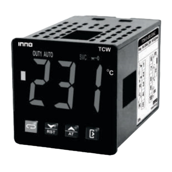
TCW-S1-UR2-230AC
Operating Manual
Introduction
A proportional–integral–derivative controller (PID controller or three
term controller) is a control loop feedback mechanism widely used in
industrial control systems and a variety of other applications requiring
continuously modulated control. A PID controller continuously
calculates an error value as the difference between a desired
setpoint (SV) and a measured process variable (PV) and applies a
correction based on proportional, integral, and derivative terms
(denoted P, I, and D respectively) which give the controller its name.
Caution for your safety
WIRING: The probe and its corresponding wires should never be
installed in a conduit next to control or power supply lines. The
electrical wiring should be done as shown in the diagram. The
power supply circuit should be connected to a protection switch.
The terminals admit wires of upto 2.5sq mm.
WARNING: Improper wiring may cause irreparable damage and
personal injury. Kindly ensure that wiring is done by qualified
personnel only.
Maintenance: Cleaning: Clean the surface of the controller with a
soft moist cloth. Do not use abrasive detergents, petrol, alcohol or
solvents.
Notice: The information in this document is subject to change in
order to improve reliability , design or function without prior notice
and does not represent a commitment on the part of the company.
In no event will the company be liable for direct, indirect, special,
incidental or consequential damage arising out of the use or
inability to use the product or documentation, even if advised of
the possibility of such damages. No part of this manual may be
reproduced or transmitted in any form or by any means without
the prior written permission of the company.
Controller:Controller should be installed in a place
protected by vibration, water and corrosive gasses and
where ambient temperature does not exceed the values
specified in the technical data.
Probe :To give a correct reading, the probe must be installed
in a place protected from thermal influences, which may
affect the temperature to be controlled.
Dimensions
48mm
TCW
48mm
Panel Cutout
45.5mm
45.5mm
Product Mounting
Installation : Fixing and dimensions of panel models:
To fix the unit, slide the fastener 1 through the guides 2 as per the
position shown in the figure. Move the fastener in the direction of the
arrow, pressing tab 3 it permits to move the fastener in the opposite
direction of the arrow.
2
1
3
48mm
PANEL
Side Lock
GASKET
CONTROLLER
Connection Diagram
L
RTD
-
N
NO
+
C
-
SSR
NC
+
Index
TM
Sr.
Description
Para.
No.
User Interface
Technical Specification
Input types & Input range
Working
Initial display when Power is ON
Parameter setting mode
Control set point.
1
Level1 Parameter
Sets the type of input sensor .
2
Sets input correction.
3
4
Sets the lower limit of PV input.
5
Sets the upper limit of PV input.
Set service time.
6
7
Factory reset parameter.
Level2 Parameter
Set control action for relay / SSR.
8
9
Runs auto tuning.
10
Sets cycle time for PID action.
Sets proportional band.
11
Sets integration time.
12
Sets differential time.
13
Sets the
hysterisis.
14
Sets Control output.
15
Lock keypad.
16
LED Indications
Error Messages
User Interface
3
2
TCW
6
7
8
9
10
11
12
Sr.
Description
No.
1
Process Value
RUN mode : Displays current measured value.
SETTING mode : Displays parameter.
Turns ON while control output is ON.
2
Turns ON when auto tunning is in progress.
3
4
Turns ON when service time elapsed.
Turns ON when keypad is locked.
5
Turns ON when the process value is > 5 C than set
6
point.
Turns ON when the process value is within the 5 C
7
range of the set point.
Turns ON when the process value is < 5 C than set
8
point.
9
Next key :
Used to enters parameters level, moves to next
parameters.
Press & hold this key atleast 1 seconds to enter
in set point mode.
Press & hold this key atleast 4 seconds to enter
in Level1.
Press & hold this key atleast 8 seconds to enter
in Level2.
Down / Reset Key :
10
Used in Program mode to decrement parameter
value.
Used to Reset SVC time.
Up / AT Key :
11
Used in Program mode to increment parameter
value.
Touch & hold this key for 2 seconds to start or stop
auto-tuning.
Exit Key :
12
Press this key to save the setting value and to exit
the programing mode.
Technical Specification
Housing
: Polycarbonate Plastic
Dimensions
: Frontal : 48 X 48mm, Depth : 78mm
Panel Cutout
: 45.5 X 45.5mm
Mounting
: Flush panel mounting with fasteners
Protection
: IP65 Front
Connections
: Terminal connectors.
< 2.5sq mm terminal only.
Display
: 3 X 20mm 7 segment White display,
7 Iconic LEDs for Indication
Data storage
: Non-volatile flash memory
Operating temp. : 0°C to 60°C (non-condensing)
Operating humidity : 20% to 85% (non-condensing)
Storage temp
: -25°C to 60°C (non-condensing)
Power input
: 230 Vac ±15 % , 50-60Hz Standard.
85 to 265 VAC/DC on request.
Control output
: Relay : 10A, 230V AC or
SSR (field selectable) : 10V DC, 30mA
Input Type
: RTD : Pt100
Thermocouple : J, K
O
O
Resolution
: 0.1 C / 1 C for RTD (Pt100) input
O
1 C for Thermocouple (J, K) input
O
Display Accuracy: RTD : 0.1% of F.S +/- 1 C
Thermocouple : 0.3% of F.S
(20 min of settling time for TC)
Sampling Period : 1 second
Input types & Input range
Decimal
Input Type
Display
Input Range ( C)
Point
J
1
-50 to 750 C
Thermocouple
K
1
-50 to 999 C
Pt
1
-99 to 400 C
RTD
100
0.1
-9.9 to 99.9 C
Working
1. Auto tuning
The Auto-tuning function automatically computes and sets the
proportional band (P), Integral time (I), Derivative time (D) as
per process characteristics.
While Auto-tune is in progress "AUTO" led will turn ON.
After Auto-tuning is complete the "AUTO" led will turn OFF.
PID-time proportional
with auto reset & rate
If auto -tuning is not complete after 3-4 cycles, it is suspected to
fail. In this case, check the wiring & parameters such as the
control action, input type etc.
Carry out the auto-tuning again, if there is a change in setpoint
or process parameters.
Note : In Auto Tunning running time, user can not change
the parameter value.
2. ON/OFF control action (For reverse mode)
The relay is 'ON' up to the set temperature and cuts"OFF"
above the set temperature . As the temperature of the system
drops ,the relay is switched 'ON' at a temperature slightly
lower than the set point .
HYSTERESIS:
The difference between the temperature at which relay
switches 'OFF' is the hysteresis or dead band.
4
5
1
Pro-key (On Request)
User can Upload parameters settings from one controller
and download them to multiple controllers.
This will make on site parameter setting easy.
Initial Display when Power is ON
When power is supplied, whole display part will be flash for
6 sec and then enters in to RUN mode.
1. Whole display Part
Parameter Setting Mode
O
SP Setting
1
Function: To set control set point.
O
Parameter
Press & hold
key for 1 seconds.
O
Display will show
. User can change
DOWN keys. Holding the key, will change the value at a faster
rate. Press
key to store the desired value & move on to
the next parameter. Set value also can be stored by pressing
Key
LEVEL1 Parameter
Press & hold
key for 4 seconds to enter into Level1
parameter setting(
will flash).
When release the key,
will flash.
Press UP/DOWN keys to modify the set value and to go to the
next parameter by pressing
key.
Press the
key to save the set value and to come out of
parameter setting after changing the set value.
2
Function: Sets the type of input sensor .
Parameter
While changing the sensor type
parameters of level1 will reset accordingly.
For type of input sensor & range please refer "Input types &
Input range" table.
3
Function: Sets input correction.
Parameter
In time it may be possible that the display may be offset by a
degree or so.
To compensate for this error, user may need to add or minus the
degrees required to achieve the correct temperature.
Example : The temperature on the display is 28 C, whereas the
O
actual temperature is 30 C. User will have to set the "
O
parameter to 2 C, which means that once out of the
programming mode, the temperature on display will be 30 C
O
O
(28 C+ 2 C).
4
Function: Sets the lower limit of PV input.
Parameter
Sets the minimum limit for set point adjustment. It can be set
from minimum specified range of selected sensor to HSV-1
value.
Once set at a particular value, this will not allow the set point
to go below this value.
When changing the setting value and SV < LSV, SV is reset
as LSV.
O
O
O
O
O
5
Function: Sets the upper limit of PV input.
Parameter
Sets the maximum limit for set point adjustment. It can be
set from LSV+1 value to maximum specified range of
selected sensor.
Once set at a particular value, this will not allow the set point
to go above this value.
When changing the setting value and SV > HSV, SV is reset
as HSV.
6
Function : To set service time.
Parameter
Service Time notify the machine user to carry out the machine
maintenance setted at predefined time or to indicate that, the
machine has worked for certain days.
Example: If user set Service time to 10 days, then after 10
days of continuous service of machine, the SVC icon on
controller will lit to indicate that service time has been elapsed
or its time to service the machine
7
Function : To restore default settings of
the controller.
Parameter
When Set to Yes all parameter are programmed to factory
values.
Useful to debug setting related problems.
Press & hold
parameter setting(
will flash.
Press UP/DOWN keys to modify the set value and to go to the
next parameter by pressing
Press the
key to save the set value and to come out of
parameter setting after changing the set value.
8
Function: Sets control action for
relay/SSR.
Parameter
This parameter used to set required control action for
relay/SSR.
= No action
= Reverse
= Forward
= PID
9
Function: Runs auto tunning.
2. Second Screen
Parameter
This parameter used to set YES/NO to start and stop Auto-
tuning.
When Setting as
Completing
is automatically Set.
During auto-tuning, the AUTO indicator continuously ON.
This parameter will be prompted only if selected control
action is PID in control parameters.
value using UP/
10
Function: Sets cycle time for PID action.
Parameter
Min
Max
Fac.
Cycle time also known as duty cycle, the total length of time for
the controller to complete one ON/OFF cycle.
O
0 C
Example : With a 20 second cycle time, an on time of 10
seconds and an OFF time of 10 seconds represents a 50
percent power output. The controller will cycle ON and OFF
while within the proportional band.
11
Function: Sets proportional band.
Parameter
Sets the proportional band of PID parameter.
Term P is proportional to the current value of the SV-PV
,
,
,
error .
Example : If the (SV-PV) error is large and positive, the
control output will be proportionately large and positive and
vice versa if error is negative.
For J type sensor
Min
Max
Fac.
12
Function: Sets integration time.
Parameter
Sets the integration time of PID parameter.
Term I accounts for past values of the SV-PV error and
integrates them over time to produce the I term.
Example : If there is a residual SV-PV error after the
application of proportional control, the integral term seeks to
O
eliminate the residual error by adding a control effect due to the
"
historic cumulative value of the error.
Setting "0" will turn OFF integration.
O
Min
Max
Fac.
O
O
O
-20 C
20 C
0 C
13
Function: Sets differential time.
Parameter
Sets the differential time of PID parameter.
Term D is a best estimate of the future trend of the SV-PV error,
based on its current rate of change. It is sometimes called
"anticipatory control", as it is effectively seeking to reduce the
effect of the SV-PV error by exerting a control influence
generated by the rate of error change. The more rapid the
change, the greater the controlling or dampening effect.
Setting "0" will turn OFF differential.
For J type sensor
Min
Max
Fac.
O
-1
O
-50 C
-50 C
For J type sensor
Min
Max
Fac.
O
O
750 C
750 C
+1
Min
Max
Fac.
999
Day
Min
Max
Fac.
LEVEL2 Parameter
key for 8 seconds to enter into Level2
will flash). When release the key,
key.
Min
Max
Fac.
, the unit starts auto-tuning. After
Min
Max
Fac.
Min
Max
Fac.
1 sec 60 sec 3 sec
Min
Max
Fac.
O
O
O
0.1 C
99.9 C
10.0 C
Min
Max
Fac.
0
999
120
sec
sec
sec
Min
Max
Fac.
0
999
30
sec
sec
sec
Advertisement

Related Manuals for INNO TCW-S1-UR2-230AC


Summary of Contents for INNO TCW-S1-UR2-230AC
- Page 1 Index Function: Sets the upper limit of PV input. Working TCW-S1-UR2-230AC Parameter Description Para. 1. Auto tuning Operating Manual The Auto-tuning function automatically computes and sets the User Interface Sets the maximum limit for set point adjustment. It can be...
-
Page 3: Sensor Type
2 C, then when the system reaches 100 C, the company. INNO AUTOMATION, reserves the right to make and Claimed Accuracy : Functions of Pro-key and the keys to be used for are as given below: the heater relay will go OFF. -
Page 4: Set Mode
4. RS 485 COMMUNICATION: Connection Diagram ( for TCW-S2-UAMR2) Technical Specification TCW-S2-UAMR2 1. Connect the TCW-S2 to PC/Laptop with the help of Housing : Polycarbonate Plastic suitable Converter (RS-485 to USB). Operating Manual Dimensions : Frontal : 48 X 48mm, Depth : 78mm 2. - Page 5 Disclaimer: This manual & its contents remain the sole property of Parameter Parameter INNO Automation . India and shall not be reproduced or distributed without authorization. Although great care has been taken in the This parameter is used to set required control action for Sets the integration time of PID parameter.
Need help?
Do you have a question about the TCW-S1-UR2-230AC and is the answer not in the manual?
Questions and answers