
Related Manuals for INNO 5G SMART


Summary of Contents for INNO 5G SMART
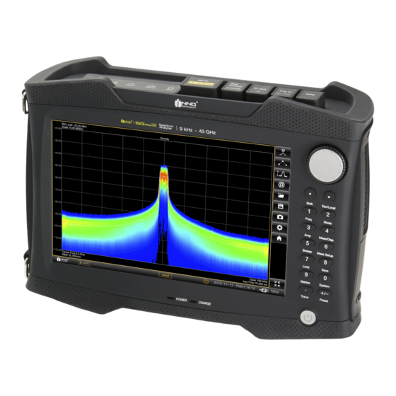
- Page 1 R1.4 5G SMART / 5G PRO Handheld Spectrum Analyzer USER GUIDE 5G SMART : 9 kHz to 15 GHz 5G PRO : 9 kHz to 43 GHz INNO INSTRUMENT INC.
-
Page 2: Table Of Contents
File Manager ............................22 Updating Firmware ..........................22 Instrument Functions ..........................23 Changing Center Frequency and Span ....................23 Change Reference Level ......................... 23 Changing Sweep MODE .......................... 24 Changing Bandwidth ..........................24 R1.3 5G SMART & 5G PRO SPECTRUM ANAYZER USER GUIDE... - Page 3 Setting Start and Stop Frequency ......................43 Setting Reference Level .......................... 44 Setting Attenuation ..........................44 Using Preamplifier ..........................44 Changing Sweep Time ..........................45 Setting Resolution Bandwidths ......................45 Setting Detector ............................. 46 R1.3 5G SMART & 5G PRO SPECTRUM ANAYZER USER GUIDE...
- Page 4 Measuring LTE-A TDD Frame Analysis ....................64 Measuring LTE-A TDD Time Alignment Error ..................64 Measuring LTE-A TDD Data Allocation Map ................... 65 Configuring LTE-A TDD Channel Scanner ....................65 R1.3 5G SMART & 5G PRO SPECTRUM ANAYZER USER GUIDE...
- Page 5 Measuring LTE-A FDD Data Channel ...................... 81 Measuring LTE-A FDD Control Channel ....................82 Measuring LTE-A FDD Frame Analysis ....................82 Measuring LTE-A FDD Data Allocation Map ................... 83 Configuring LTE-A FDD Channel Scanner ....................83 R1.3 5G SMART & 5G PRO SPECTRUM ANAYZER USER GUIDE...
- Page 6 Measuring 5GNR Multi Beam ......................... 98 Measuring 5GNR Single Beam ........................ 98 Upgrading Software License ........................100 Checking a License Information ......................100 Importing Software License ........................100 INNO Warranty Terms and Conditions ..................... 101 R1.3 5G SMART & 5G PRO SPECTRUM ANAYZER USER GUIDE...
-
Page 7: Safety Instruction For Rechargeable Lithium-Ion Battery
Keep the batteries clean and dry. If the terminals become soiled, clean them with a dry, clean cloth. Charge the batteries prior to using them. Only use the appropriate INNO Instrument charger provided with the instrument to charge the batteries. If the batteries are improperly charged, there is a risk of explosion, which can cause serious personal injury. - Page 8 For warranty service or repair, this product must be returned to a service facility designated by INNO Instrument. For more information, see “INNO Warranty Terms and Conditions.”...
-
Page 9: Getting Started
Slide babery cover to open posicon located on the babery compartment. Open the cover. Insert the provided babery into the Spectrum Analyzer. Close the cover and slide cover to close posicon. R1.3 5G SMART & 5G PRO SPECTRUM ANAYZER USER GUIDE... -
Page 10: Using Ac Adapter
Risk of instrument damage. To avoid instrument damage, Ÿ Only use the power supply (INNO Instrument, ADP-65JH BBFC) included in the package. Ÿ Make sure that the AC supply voltage is compatible to the voltage specified on the power supply unit. -
Page 11: Instrument Overview
Risk of damage To avoid damage to the coupling capacitor, input attenuator or the mixer, the DC input voltage must never exceed the value specified in the data sheet. R1.3 5G SMART & 5G PRO SPECTRUM ANAYZER USER GUIDE... -
Page 12: Touchscreen Display
Ÿ Do not apply excessive force to the screen. Touch it gently. Ÿ Do not scratch the screen surface, e.g. with a fingernail. Do not rub it strongly, for example with a dust cloth. R1.3 5G SMART & 5G PRO SPECTRUM ANAYZER USER GUIDE... -
Page 13: Measurement Information Window
& length. Ÿ Tab on the trace window to select a key or item. Ÿ Touch screen does not support multi-touch gestures with two fingers operation. R1.3 5G SMART & 5G PRO SPECTRUM ANAYZER USER GUIDE... -
Page 14: Home Screen
HOME SCREEN All measurement available in the Spectrum Analyzer are displayed on the screen. Tab to select and run measurement. SHORTCUTS Quickly access using the shortcuts. R1.3 5G SMART & 5G PRO SPECTRUM ANAYZER USER GUIDE... -
Page 15: Changing Mode
Supported mode: − Spectrum Analyzer − Realcme Spectrum Analyzer − LTE FDD Analyzer − LTE TDD Analyzer − 5GR Analyzer R1.3 5G SMART & 5G PRO SPECTRUM ANAYZER USER GUIDE... -
Page 16: On-Screen Keyboard
Navigation keys A cursor key to increase or decrease value or move right or left. Confirmed the value Ÿ All the values will be confirmed by selecting the unit. R1.3 5G SMART & 5G PRO SPECTRUM ANAYZER USER GUIDE... -
Page 17: Function Keys
− Occupied bandwidth (OBW) − Spectrum emission mask (Spectrum Emission Mask) − Multicarrier adjacent channel power (ACP) Measure Setup This key provides detailed setup menu available in the selected measurements. R1.3 5G SMART & 5G PRO SPECTRUM ANAYZER USER GUIDE... -
Page 18: Status Bar
Shows the results by measurement item in the selected mode. Realcme Spectrum Analyzer measurement results support dual-display: − Realcme Spectrogram (Top Spectrum + Bobom Spectrogram) − Persistent Spectrogram (top Spectrogram + bobom Persistent Spectrum) R1.3 5G SMART & 5G PRO SPECTRUM ANAYZER USER GUIDE... - Page 19 In dual-display mode, the measurement highlighted in the yellow box indicates the active window, and all settings are displayed relative to the active window. R1.3 5G SMART & 5G PRO SPECTRUM ANAYZER USER GUIDE...
-
Page 20: Instrument Settings
USING GPS RECEIVER Spectrum analyzer can locate exact posicon by providing the GPS antenna to the GPS connector. The "Instrument Setup" provides all seengs necessary to configure the GPS. R1.3 5G SMART & 5G PRO SPECTRUM ANAYZER USER GUIDE... -
Page 21: Configuring Power On Setting
Outdoor display changes the color seeng to high contrast black and white display mode enhances screen readability under the direct sun-light. Night display provides screen readability under the dark environment minimize dazzling. R1.3 5G SMART & 5G PRO SPECTRUM ANAYZER USER GUIDE... -
Page 22: Configuring Date And Time
Spectrum analyzer has an internal clock that can apply a date and cmestamp. In the "Setup" dialog box, you can set both date and cme. And you can also set the data formats. CONFIGURING NETWORK Spectrum analyzer provides Remote Interface to control the instrument remotely. R1.3 5G SMART & 5G PRO SPECTRUM ANAYZER USER GUIDE... -
Page 23: File Manager
Select Upgrade. A dialog box appears displaying the update progress in % and instruccng you to complete the firmware update by restarcng the instrument. Restart the instrument to complete the updates. R1.3 5G SMART & 5G PRO SPECTRUM ANAYZER USER GUIDE... -
Page 24: Instrument Functions
) or Frequency Informacon box to adjust the center frequency and Span (X-scale) of the spectrum measurement. CHANGE REFERENCE LEVEL Tab Amplitude key ( ) or press Amplitude Informacon box to adjust the amplitude (Y-scale) of the spectrum measurement. R1.3 5G SMART & 5G PRO SPECTRUM ANAYZER USER GUIDE... -
Page 25: Changing Sweep Mode
) or press Sweep Informacon box to adjust the sweep mode of the spectrum measurement. CHANGING BANDWIDTH Tab Bandwidth key ( ) or press Bandwidth Informacon box to adjust the RBW, VBW of the spectrum measurement. R1.3 5G SMART & 5G PRO SPECTRUM ANAYZER USER GUIDE... -
Page 26: Set Up Triggering
) or press Trigger Informacon box to set up triggering. Trigger menu does not appear in normal operacon mode. It can be controlled in zero span. The spectrum analyzer provides the following Trigger modes. R1.3 5G SMART & 5G PRO SPECTRUM ANAYZER USER GUIDE... -
Page 27: Adding Trace
) or press Trace Informacon box to add traces of the spectrum measurement. How to accvate trace(s): Select Trace (from T1 to T6). Select Trace Property (Clear Write, Max Hold, Min Hold, View (Capture), Average). Turn Trace On. R1.3 5G SMART & 5G PRO SPECTRUM ANAYZER USER GUIDE... - Page 28 The view trace mode freezes the current trace and aborts the measurement. Using the view trace mode is an effeccve way to evaluate the trace, for example with markers. R1.3 5G SMART & 5G PRO SPECTRUM ANAYZER USER GUIDE...
-
Page 29: Adding Marker
If you delete marker 1 (M1), all delta markers that are relative to that marker are also deleted. Peak Search: Tab Marker Shortcut – Peak Search ( Select Marker Property or R1.3 5G SMART & 5G PRO SPECTRUM ANAYZER USER GUIDE... -
Page 30: Moving Marker
With the frequency counter, however, you can get a more accurate result of the horizontal marker posicon. R1.3 5G SMART & 5G PRO SPECTRUM ANAYZER USER GUIDE... -
Page 31: Configuring Measurement
Available measurements may differ from the different modes. Available measurements that show specifics for each operacng mode or measurement are provided in the corresponding seccons of this guide. R1.3 5G SMART & 5G PRO SPECTRUM ANAYZER USER GUIDE... -
Page 32: Spectrum Analyzer Mode
Screen layouts that show specifics for each operacng mode or measurement are provided in the corresponding seccons of this guide. R1.3 5G SMART & 5G PRO SPECTRUM ANAYZER USER GUIDE... -
Page 33: Setting Frequency And Span
The horizontal axis becomes the time axis. The display always starts at 0 s and stops after the currently set sweep time. R1.3 5G SMART & 5G PRO SPECTRUM ANAYZER USER GUIDE... -
Page 34: Setting Reference Level
If you want to measure signals with low powers, you can turn it on. Tab the Amplitude key. Turn On and Off the "Preamp". R1.3 5G SMART & 5G PRO SPECTRUM ANAYZER USER GUIDE... -
Page 35: Setting Resolution Bandwidths
Select the "Auto VBW" sodkey again to couple the video bandwidth to the RBW. The spectrum analyzer has video bandwidths from 1 Hz to 5 MHz in a 1-3-10 sequence. R1.3 5G SMART & 5G PRO SPECTRUM ANAYZER USER GUIDE... -
Page 36: Setting Detector
Noise measurements also provide stable results if you apply the RMS detector in combinacon with a high sweep cme. R1.3 5G SMART & 5G PRO SPECTRUM ANAYZER USER GUIDE... -
Page 37: Gated Sweep Mode
Gated Sweep mode is only available on instrument with Gated Sweep option installed. Gate View On (Change to Time-domain to set Gate- Gate On (Change to Frequency-domain with the Gate delay and length) Gated sweep seengs) R1.3 5G SMART & 5G PRO SPECTRUM ANAYZER USER GUIDE... -
Page 38: Configuring Measurement
It determines the total power of the channel by integracng the results on the trace. The following parameters need to be configured to perform channel power measurement using Measure Setup key ( Channel Bandwidth to be measured. R1.3 5G SMART & 5G PRO SPECTRUM ANAYZER USER GUIDE... -
Page 39: Measuring Occupied Bandwidth
Therefore, the spectrum analyzer provides predefined spectrum emission masks for various telecommunicacons standards. R1.3 5G SMART & 5G PRO SPECTRUM ANAYZER USER GUIDE... -
Page 40: Measuring Adjacent Channel Power (Acp)
The following parameters need to be configured to perform channel power measurement using Measure Setup key ( Main Channel Bandwidth to be measured. Adjacent Channel Bandwidth to be measured. Alternate Channel Bandwidth to be measured. R1.3 5G SMART & 5G PRO SPECTRUM ANAYZER USER GUIDE... - Page 41 The channel bandwidth must be smaller than the frequency span (span > channel bandwidth) R1.3 5G SMART & 5G PRO SPECTRUM ANAYZER USER GUIDE...
-
Page 42: Realtime Spectrum Analyzer Mode
Realcme Spectrum Analyzer. Screen layouts that show specifics for each operacng mode or measurement are provided in the corresponding seccons of this guide. R1.3 5G SMART & 5G PRO SPECTRUM ANAYZER USER GUIDE... -
Page 43: Function Keys
This key provides detailed setup menu available in the selected measurements. All Settings This key provides all settings window. Available items in function key can be different per different mode of operations. R1.3 5G SMART & 5G PRO SPECTRUM ANAYZER USER GUIDE... -
Page 44: Setting Frequency And Span
If you have entered a stop frequency that is outside the maximum frequency range of the instrument, then the realtime spectrum analyzer sets the stop frequency to the possible maximum. R1.3 5G SMART & 5G PRO SPECTRUM ANAYZER USER GUIDE... -
Page 45: Setting Reference Level
If you want to measure signals with low powers, you can turn it on. Tab the Amplitude key. Turn On and Off the "Preamp". R1.3 5G SMART & 5G PRO SPECTRUM ANAYZER USER GUIDE... -
Page 46: Changing Sweep Time
Gausian Blackmann-Harris Kaiser Flabop The windowing function is coupled to the resolution bandwidth, therefore the available RBW settings are differ by the selected FFT window type. R1.3 5G SMART & 5G PRO SPECTRUM ANAYZER USER GUIDE... -
Page 47: Setting Detector
Nega4ve Peak: The min peak detector displays sine signals with the correct level and suppresses noise. Therefore it is useful to find sine signals in the vicinity of noise. R1.3 5G SMART & 5G PRO SPECTRUM ANAYZER USER GUIDE... -
Page 48: Adding Marker
(click and drag). When Marker is enabled, Marker Table will be displayed on the bobom of the measure result with the corresponding frequency and amplitude informacon. Realcme Spectrum Analyzer supports 6 markers, five of which can be used as either markers or delta markers. R1.3 5G SMART & 5G PRO SPECTRUM ANAYZER USER GUIDE... -
Page 49: Moving Marker
This involves with the several variables in the calculacon of the noise power density, including the trace pixel values, the resolucon bandwidth, the detector, and the level display mode (absolute or relacve). R1.3 5G SMART & 5G PRO SPECTRUM ANAYZER USER GUIDE... -
Page 50: Configuring Measurement
In Density view, high density is represented by the color at the top of the color bar and low density by the color at the bobom of the color bar. R1.3 5G SMART & 5G PRO SPECTRUM ANAYZER USER GUIDE... -
Page 51: Using Realtime Spectrogram
Y-axis represents amplitude and the Z-axis represents number of hits. This view therefore displays three-dimensional data on a two-dimensional display, using color to represent the third dimension. R1.3 5G SMART & 5G PRO SPECTRUM ANAYZER USER GUIDE... -
Page 52: Using Persistent Spectrogram
The persistent spectrogram is a combinacon of spectrogram which is an easy way to monitor the changes of a signal's frequency and amplitude over cme and persistent density include how frequent a certain level and frequency combinacon has occurred during the measurement R1.3 5G SMART & 5G PRO SPECTRUM ANAYZER USER GUIDE... -
Page 53: Lte-A Tdd Analyzer Mode
LTE-A TDD analyzer. Screen layouts that show specifics for each operacng mode or measurement are provided in the corresponding seccons of this guide. R1.3 5G SMART & 5G PRO SPECTRUM ANAYZER USER GUIDE... -
Page 54: Setting Center Frequency And Span
Tab the Amplitude key. Select the "Ref Level" sodkey. Enter the reference level in an open field. R1.3 5G SMART & 5G PRO SPECTRUM ANAYZER USER GUIDE... -
Page 55: Setting Attenuation
Select the detector from the submenu. If the "Auto Detector" seleccon is accve, the seleccon of the trace detector is always “Normal.” The LTE-A TDD analyzer provides several types of detectors. R1.3 5G SMART & 5G PRO SPECTRUM ANAYZER USER GUIDE... -
Page 56: Adding Trace
ADDING TRACE Tab Trace key ( ) or press Trace Informacon box to add traces of the LTE-A TDD spectrum measurement. How to accvate trace(s): Select Trace (from T1 to T6). R1.3 5G SMART & 5G PRO SPECTRUM ANAYZER USER GUIDE... - Page 57 The trace shows the minimum power levels that have been measured at each pixel. To overwrite a min hold trace, change a parameter in a way that the results cannot be compared any more (e.g. R1.3 5G SMART & 5G PRO SPECTRUM ANAYZER USER GUIDE...
-
Page 58: Adding Marker
If you delete marker 1 (M1), all delta markers that are relative to that marker are also deleted. MOVING MARKER Tab and drag on the marker bar or icon to change the marker posicon in the trace window. R1.3 5G SMART & 5G PRO SPECTRUM ANAYZER USER GUIDE... -
Page 59: Marker Function
(absolute or relacve). CONFIGURING LTE-A TDD CHANNEL POWER Measure Setup key ( ) provides all available configuracons (required seengs) of the LTE-A TDD channel power measurements R1.3 5G SMART & 5G PRO SPECTRUM ANAYZER USER GUIDE... -
Page 60: Measuring Lte-A Tdd Channel Power
It determines the total power of the channel by integracng the results on the trace. CONFIGURING LTE-A TDD OCCUPIED BANDWIDTH Measure Setup key ( ) provides all available configuracons (required seengs) of the LTE-A TDD occupied bandwidth measurements R1.3 5G SMART & 5G PRO SPECTRUM ANAYZER USER GUIDE... -
Page 61: Measuring Lte-A Tdd Occupied Bandwidth
10 % to 99.9 %. CONFIGURING LTE-A TDD POWER VS TIME Measure Setup key ( ) provides all available configuracons (required seengs) of the LTE-A TDD Power vs Time measurements R1.3 5G SMART & 5G PRO SPECTRUM ANAYZER USER GUIDE... -
Page 62: Measuring Lte-A Tdd Frame
The Frame measurement provide a power of the frame and subframes with the relevant parameters such as Cell ID, IQ Origin Offset and Time Offset. MEASURING LTE-A TDD SLOT The Slot measurement provide a slot power, DwPTS Avg Power and DwPTS Time. R1.3 5G SMART & 5G PRO SPECTRUM ANAYZER USER GUIDE... -
Page 63: Configuring Lte-A Tdd Modulation Analysis
The Constellacon measurement displays the posicon of the demodulated signal on the IQ plot. 5G Pro and Smart measures and displays QPSK, 16 QAM, 64 QAM and 256 QAM. Measurement results include RSRP and EVM. R1.3 5G SMART & 5G PRO SPECTRUM ANAYZER USER GUIDE... -
Page 64: Measuring Lte-A Tdd Data Channel
The Control Channel measurement displays the constellacon of the selected Control Channel with the relevant parameters such as M-Type(Modulacon type) and PBCH EVM(RMS and Peak). It also measures Freq Offset and IQ offset in a received signal. R1.3 5G SMART & 5G PRO SPECTRUM ANAYZER USER GUIDE... -
Page 65: Measuring Lte-A Tdd Frame Analysis
MEASURING LTE-A TDD TIME ALIGNMENT ERROR The Time Alignment Error measures and displays the cme delay between two signals by analyzing two or more signals flowing into each antenna in TX Diversity system. R1.3 5G SMART & 5G PRO SPECTRUM ANAYZER USER GUIDE... -
Page 66: Measuring Lte-A Tdd Data Allocation Map
The Data Allocacon Map measure displays data allocacon in frames. CONFIGURING LTE-A TDD CHANNEL SCANNER Measure Setup key ( ) provides all available configuracons (required seengs) of the LTE-A TDD Channel Scanner measurements R1.3 5G SMART & 5G PRO SPECTRUM ANAYZER USER GUIDE... -
Page 67: Measuring Lte-A Tdd Channel Scanner
The Channel Scanner sequencally analyzes and displays the mulc-channel signal coming through the antenna. CONFIGURING LTE-A TDD ID SCANNER Measure Setup key ( ) provides all available configuracons (required seengs) of the LTE-A TDD ID Scanner measurements R1.3 5G SMART & 5G PRO SPECTRUM ANAYZER USER GUIDE... -
Page 68: Measuring Lte-A Tdd Id Scanner
IDs, RSRP, RSRQ, RS-SINR, RSSI, P-SS and S-SS. CONFIGURING LTE-A TDD CONTROL CHANNEL Measure Setup key ( ) provides all available configuracons (required seengs) of the LTE-A TDD Control Channel measurements R1.3 5G SMART & 5G PRO SPECTRUM ANAYZER USER GUIDE... -
Page 69: Measuring Lte-A Tdd Control Channel
The Control Channel provide analysis results of all control channels over cme. CONFIGURING LTE-A TDD DATAGRAM Measure Setup key ( ) provides all available configuracons (required seengs) of the LTE-A TDD Datagram measurements R1.3 5G SMART & 5G PRO SPECTRUM ANAYZER USER GUIDE... -
Page 70: Measuring Lte-A Tdd Datagram
The Datagram displays a spectrum of changes in signal power over cme. CONFIGURING LTE-A TDD CARRIER AGGREGATION Measure Setup key ( ) provides all available configuracons (required seengs) of the LTE-A TDD Carrier Aggregacon measurements R1.3 5G SMART & 5G PRO SPECTRUM ANAYZER USER GUIDE... -
Page 71: Measuring Lte-A Tdd Carrier Aggregation
MEASURING LTE-A TDD CARRIER AGGREGATION The Carrier Aggregacon displays the measurement results of mulcple LTE carriers used to provide high data rates. R1.3 5G SMART & 5G PRO SPECTRUM ANAYZER USER GUIDE... -
Page 72: Lte-A Fdd Analyzer Mode
LTE-A FDD analyzer. Screen layouts that show specifics for each operacng mode or measurement are provided in the corresponding seccons of this guide. R1.3 5G SMART & 5G PRO SPECTRUM ANAYZER USER GUIDE... -
Page 73: Setting Center Frequency And Span
Tab the Amplitude key. Select the "Ref Level" sodkey. Enter the reference level in an open field. R1.3 5G SMART & 5G PRO SPECTRUM ANAYZER USER GUIDE... -
Page 74: Setting Attenuation
Select the detector from the submenu. If the "Auto Detector" seleccon is accve, the seleccon of the trace detector is always “Normal.” The LTE-A FDD analyzer provides several types of detectors. R1.3 5G SMART & 5G PRO SPECTRUM ANAYZER USER GUIDE... -
Page 75: Adding Trace
ADDING TRACE Tab Trace key ( ) or press Trace Informacon box to add traces of the LTE-A FDD spectrum measurement. How to accvate trace(s): Select Trace (from T1 to T6). R1.3 5G SMART & 5G PRO SPECTRUM ANAYZER USER GUIDE... - Page 76 The trace shows the minimum power levels that have been measured at each pixel. To overwrite a min hold trace, change a parameter in a way that the results cannot be compared any more (e.g. R1.3 5G SMART & 5G PRO SPECTRUM ANAYZER USER GUIDE...
-
Page 77: Adding Marker
Deactivating markers If you delete marker 1 (M1), all delta markers that are relative to that marker are also deleted. R1.3 5G SMART & 5G PRO SPECTRUM ANAYZER USER GUIDE... -
Page 78: Moving Marker
(absolute or relacve). CONFIGURING LTE-A FDD CHANNEL POWER Measure Setup key ( ) provides all available configuracons (required seengs) of the LTE-A FDD channel power measurements R1.3 5G SMART & 5G PRO SPECTRUM ANAYZER USER GUIDE... -
Page 79: Measuring Lte-A Fdd Channel Power
It determines the total power of the channel by integracng the results on the trace. CONFIGURING LTE-A FDD OCCUPIED BANDWIDTH Measure Setup key ( ) provides all available configuracons (required seengs) of the LTE-A FDD occupied bandwidth measurements R1.3 5G SMART & 5G PRO SPECTRUM ANAYZER USER GUIDE... -
Page 80: Measuring Lte-A Fdd Occupied Bandwidth
If you need another percentage for the occupied bandwidth, you can set values from 10 % to 99.9 %. CONFIGURING LTE-A FDD FRAME Measure Setup key ( ) provides all available configuracons (required seengs) of the LTE-A FDD Power vs Time measurements R1.3 5G SMART & 5G PRO SPECTRUM ANAYZER USER GUIDE... -
Page 81: Measuring Lte-A Fdd Frame
Cell ID, IQ Origin Offset, Time Offset and etc. CONFIGURING LTE-A FDD MODULATION ANALYSIS Measure Setup key ( ) provides all available configuracons (required seengs) of the LTE-A FDD Modulacon Analysis measurements R1.3 5G SMART & 5G PRO SPECTRUM ANAYZER USER GUIDE... -
Page 82: Measuring Lte-A Fdd Constellation
The Data Channel measurement displays the constellacon of the selected Resource Block with the relevant parameters such as M-Type(Modulacon type), RB Power and EVM(RMS and Peak). It also measures IQ offset in a received signal. R1.3 5G SMART & 5G PRO SPECTRUM ANAYZER USER GUIDE... -
Page 83: Measuring Lte-A Fdd Control Channel
Frame Avg Power, OFDM Symbol Power, Data EVM(RMS and Peak) and EVM(RMS and Peak). It also measures Freq Offset and IQ Origin Offset in a received signal. R1.3 5G SMART & 5G PRO SPECTRUM ANAYZER USER GUIDE... -
Page 84: Measuring Lte-A Fdd Data Allocation Map
The Data Allocacon Map measure displays data allocacon in frames. CONFIGURING LTE-A FDD CHANNEL SCANNER Measure Setup key ( ) provides all available configuracons (required seengs) of the LTE-A FDD Channel Scanner measurements R1.3 5G SMART & 5G PRO SPECTRUM ANAYZER USER GUIDE... -
Page 85: Measuring Lte-A Fdd Channel Scanner
The Channel Scanner sequencally analyzes and displays the mulc-channel signal coming through the antenna. CONFIGURING LTE-A FDD ID SCANNER Measure Setup key ( ) provides all available configuracons (required seengs) of the LTE-A FDD ID Scanner measurements R1.3 5G SMART & 5G PRO SPECTRUM ANAYZER USER GUIDE... -
Page 86: Measuring Lte-A Fdd Id Scanner
IDs, RSRP, RSRQ, RS-SINR, RSSI, P-SS and S-SS. CONFIGURING LTE-A FDD CONTROL CHANNEL Measure Setup key ( ) provides all available configuracons (required seengs) of the LTE-A FDD Control Channel measurements R1.3 5G SMART & 5G PRO SPECTRUM ANAYZER USER GUIDE... -
Page 87: Measuring Lte-A Fdd Control Channel
The Control Channel provide analysis results of all control channels over cme. CONFIGURING LTE-A FDD DATAGRAM Measure Setup key ( ) provides all available configuracons (required seengs) of the LTE-A FDD Datagram measurements R1.3 5G SMART & 5G PRO SPECTRUM ANAYZER USER GUIDE... -
Page 88: Measuring Lte-A Fdd Datagram
The Datagram displays a spectrum of changes in signal power over cme. CONFIGURING LTE-A FDD CARRIER AGGREGATION Measure Setup key ( ) provides all available configuracons (required seengs) of the LTE-A FDD Carrier Aggregacon measurements R1.3 5G SMART & 5G PRO SPECTRUM ANAYZER USER GUIDE... -
Page 89: Measuring Lte-A Fdd Carrier Aggregation
MEASURING LTE-A FDD CARRIER AGGREGATION The Carrier Aggregacon displays the measurement results of mulcple LTE carriers used to provide high data rates. R1.3 5G SMART & 5G PRO SPECTRUM ANAYZER USER GUIDE... -
Page 90: 5Gnr Signal Analyzer Mode
5GNR signal analyzer. Screen layouts that show specifics for each operacng mode or measurement are provided in the corresponding seccons of this guide. R1.3 5G SMART & 5G PRO SPECTRUM ANAYZER USER GUIDE... -
Page 91: Setting Center Frequency And Span
61.44 MHz 40 MHz 61.44 MHz 50 MHz 61.44 MHz 60 MHz 122.88 MHz 70 MHz 122.88 MHz 80 MHz 122.88 MHz 90 MHz 122.88 MHz 100 MHz 122.88 MHz R1.3 5G SMART & 5G PRO SPECTRUM ANAYZER USER GUIDE... -
Page 92: Setting Reference Level
5GNR signal analyzer, the preamplifier is turned off. If you want to measure signals with low powers, you can turn it on. Tab the Amplitude key. Turn On and Off the "Preamp". R1.3 5G SMART & 5G PRO SPECTRUM ANAYZER USER GUIDE... -
Page 93: Setting Detector
Noise measurements also provide stable results if you apply the Average detector in combinacon with a high sweep cme. R1.3 5G SMART & 5G PRO SPECTRUM ANAYZER USER GUIDE... -
Page 94: Adding Trace
The 5GNR signal analyzer provides the following trace modes. Clear/Write: In its default state, the 5GNR signal analyzer overwrites the trace ader each sweep. You can apply all detectors in this mode. Average: R1.3 5G SMART & 5G PRO SPECTRUM ANAYZER USER GUIDE... -
Page 95: Adding Marker
(click and drag). When Marker is enabled, Marker Table will be displayed on the bobom of the measure result with the corresponding frequency and amplitude informacon. 5GNR signal analyzer supports 6 markers, five of which can be used as either markers or delta markers. R1.3 5G SMART & 5G PRO SPECTRUM ANAYZER USER GUIDE... -
Page 96: Moving Marker
(absolute or relacve). CONFIGURING 5GNR CHANNEL POWER Measure Setup key ( ) provides all available configuracons (required seengs) of the 5GNR channel power measurements R1.3 5G SMART & 5G PRO SPECTRUM ANAYZER USER GUIDE... -
Page 97: Measuring 5Gnr Channel Power
It determines the total power of the channel by integracng the results on the trace. CONFIGURING 5GNR OCCUPIED BANDWIDTH Measure Setup key ( ) provides all available configuracons (required seengs) of the 5GNR occupied bandwidth measurements R1.3 5G SMART & 5G PRO SPECTRUM ANAYZER USER GUIDE... -
Page 98: Measuring 5Gnr Occupied Bandwidth
If you need another percentage for the occupied bandwidth, you can set values from 10 % to 99.9 %. CONFIGURING 5GNR DEMODULATION MEASUREMENT Measure Setup key ( ) provides all available configuracons (required seengs) of the 5GNR demodulacon measurements. R1.3 5G SMART & 5G PRO SPECTRUM ANAYZER USER GUIDE... -
Page 99: Measuring 5Gnr Multi Beam
The single beam measurement provides beam specific parameters such as EVM RMS and Peak. All 8 beams can be measured and you can navigate using page indicator on the bobom of the measurement result window. R1.3 5G SMART & 5G PRO SPECTRUM ANAYZER USER GUIDE... - Page 100 R1.3 5G SMART & 5G PRO SPECTRUM ANAYZER USER GUIDE...
-
Page 101: Upgrading Software License
Email the file to INNO. IMPORTING SOFTWARE LICENSE Ader receiving a new license file from INNO, place the file on the USB flash drive in the top (root) level, not in any directory. Plug USB flash drive contains the new license file to the instrument. -
Page 102: Inno Warranty Terms And Conditions
EXCLUDED from this transac<on and shall not apply. The purchaser agrees that his sole and exclusive remedy against INNO Instrument Inc. shall be for the repair or replacement of defec<ve parts as provided hereinabove. The purchaser agrees that NO OTHER REMEDY (including, but not limited to, incidental or consequen<al damages for lost profits, lost sales, injury to person or property, or... - Page 103 The purchaser acknowledges that no oral-statements purpor<ng to be warran<es, representa<ons, or guarantees of any product from INNO Instrument Inc. have been made by INNO Instrument Inc. or its dealer which in any way expands, alters or modifies the terms of the warranty set out herein. Any such statements do not cons<tute warran<es, shall not be relied on by the purchaser, and are not part of the contract of sale.
- Page 104 End of contents R1.3 5G SMART & 5G PRO SPECTRUM ANAYZER USER GUIDE...
- Page 105 82 32 837 5601 R1.3 5G SMART & 5G PRO SPECTRUM ANAYZER USER GUIDE 5G SMART / 5G PRO Spectrum Analyzer User Guide Rev. 1.3 Visit us at www.innoinstrument.com Product specifica/ons and descrip/ons in this document subject to change without no/ce...
Need help?
Do you have a question about the 5G SMART and is the answer not in the manual?
Questions and answers