Table of Contents
Advertisement
Quick Links
INSTALLATION
INSTRUCTIONS
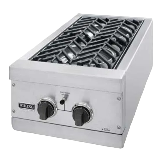
VGSB T-SERIES OUTDOOR 15" WIDE DOUBLE SIDE BURNERS
& VGRT 24" WIDE OUTDOOR RANGETOP
Retain for Future Reference
IMPORTANT: PLEASE READ AND FOLLOW
1. Before beginning, please read these instructions completely and carefully.
2. Do not remove permanently affixed labels, warnings, or plates from product. This may void the warranty
3. Please observe all local and national codes and ordinances.
4. The installer should leave these instructions with the consumer who should retain for local inspector's use and for
future reference
Installation must conform with local codes or in the absence of codes, the National Fuel Gas Code, ANSI Z223.1.
In Canada: Installation must be in accordance with the current CAN/CGA-B149.1, Natural Gas Installation Code or
CAN/CGA-B149.2, Propane Installation Code and/or local codes.
FOR YOUR SAFETY
If you smell gas:
1. Shut off gas to the appliance.
2. Extinguish any open flame.
3. Open lid.
4. If odor continues, immediately call your gas supplier or your
fire department.
FOR YOUR SAFETY
1. Do not store or use gasoline or other flammable vapors
and liquids in the vicinity of this or any other appliance.
2. Any LP cylinder not connected for use shall not be stored
in the vicinity of this or any other appliance.
WARNING
If not installed, operated and maintained in
accordance with the manufacturer's instructions, this
product could expose you to substances in fuel or
fuel combustion which can cause death or serious
illness and which are known to cause cancer, birth
defects or other reproductive harm.
For example, benzene is a chemical which is
part of the gas supplied to the cooking
product. It is consumed in the flame during
combustion. However, exposure to a small
amount of benzene is possible if a gas leak
occurs. Formaldehyde and soot are by-
products of incomplete combustion. Properly
adjusted burners with a bluish rather than
yellow flame minimize incomplete combustion.
1
Advertisement
Table of Contents

Related Manuals for Viking VGRT242T


Summary of Contents for Viking VGRT242T
- Page 1 INSTALLATION INSTRUCTIONS VGSB T-SERIES OUTDOOR 15” WIDE DOUBLE SIDE BURNERS & VGRT 24” WIDE OUTDOOR RANGETOP Retain for Future Reference IMPORTANT: PLEASE READ AND FOLLOW 1. Before beginning, please read these instructions completely and carefully. 2. Do not remove permanently affixed labels, warnings, or plates from product. This may void the warranty 3.
-
Page 2: Basic Specifications
BASIC SPECIFICATIONS Description Overall Width Overall Depth Overall Height Cutout Width Cutout Depth Cutout Height Requirements Side Burner Rating Approximate Shipping Wt. GENERAL INFORMATION WARNING: This outdoor gas side burner is not intended to be installed in or on recreational vehicles and/or boats. -
Page 3: Natural Fixed Piping Connection
Check with your local gas utility company or with local codes for instructions on installing gas supply lines. Be sure to check on type and size of run and how deep to bury the lines. If the gas line is too small, the grill will not function properly. -
Page 4: Lp/Propane Fixed Piping Connection
Check with your local gas utility company or with local codes for instructions on installing gas supply lines. Be sure to check on type and size of run and how deep to bury the lines. If the gas line is too small, the grill will not function properly. -
Page 5: Lp/Propane Tank Connection
LP/Propane tank main valve “OFF” after each use and during transport of the tank or unit. First connect the regulator to the grill unit by screwing the 3/8” flare coupling ot the 3/8” flare adaptor. Connect to the tank valve by screwing the Type 1, QCC-1 connector to the LP/Propane tank. -
Page 6: Leak Testing
Do not attempt to repair the cylinder valve if it should become damaged. The cylinder must be replaced. 8. If you are unable to stop a leak, shut off the gas supply at the cylinder valve. Remove the cylinder from the grill. Call an authorized gas appliance service technician or LP/Propane gas dealer. - Page 7 INSTALLATION PROCEDURES FOR BUILT-IN INSTALLATION 1. A minimum of 6” (15.2 cm) from the sides must be maintained from the side burners above the cooking surface to adjacent vertical combustible construction. The unit is not to be located under overhead unprotected combustible construction. 2.
-
Page 8: Front View
Front View VGSB152T Front View VGRT244T Min. 6” (15.2 cm) combustible surfaces Min. 6” (15.2 cm) combustible surfaces 15 5/16” (38.9 cm) 26 1/4” (66.7 cm) - Page 9 Built-In Clearance Dimensions Side View...
-
Page 10: Ventilation For Built-In Installations
VENTILATION FOR BUILT-IN INSTALLATIONS No more than 5.00 inches above the floor of the installation. 1. At least one ventilation opening shall be provided on the exposed exterior side of the enclosure located within 5 inches (127 mm) of the top of the enclosure and unobstructed. The opening(s) shall have a total free area of not less than 1 in /lb (14.2 cm /kg) of stored fuel capacity. -
Page 11: Burner Adjustment
2. If the flame is noisy and lifting away from the burner, turn the air shutter clockwise to reduce the amount of air to the burner. Once adjusted, turn the burner off, tighten the set screw on the air shutter, replace the valve panel for the grill burners and the grate support, burner bowls, and grates for the side burners. -
Page 12: Performance Checklist
Only authorized replacement parts may be used in performing service on the side burners. Do not repair or replace any part of the outdoor grill unless specifically recommended in the manual. All other servicing should be referred to a qualified... - Page 13 VIKING RANGE CORPORATION 111 Front Street • Greenwood, Mississippi 38930 USA • (662) 455-1200 Specifications subject to change without notice. www.vikingrange.com F20056I (071907J)
Need help?
Do you have a question about the VGRT242T and is the answer not in the manual?
Questions and answers