Table of Contents
Advertisement
Quick Links
Technical Support and E-Warranty Certificate www.vevor.com/support
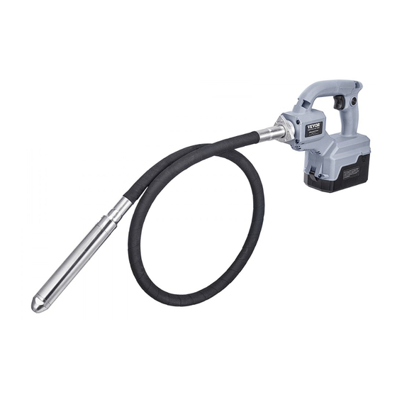
Cordless Concrete Vibrator
USER MANUAL
MODEL: FTC5220
We continue to be committed to provide you tools with competitive price.
"Save Half", "Half Price" or any other similar expressions used by us only represents an
estimate of savings you might benefit from buying certain tools with us compared to the
major top brands and doses not necessarily mean to cover all categories of tools offered by
us. You are kindly reminded to verify carefully when you are placing an order with us if you
are actually saving half in comparison with the top major brands.
Advertisement
Table of Contents

Subscribe to Our Youtube Channel
Related Manuals for VEVOR FTC5220


Summary of Contents for VEVOR FTC5220
- Page 1 Technical Support and E-Warranty Certificate www.vevor.com/support Cordless Concrete Vibrator USER MANUAL MODEL: FTC5220 We continue to be committed to provide you tools with competitive price. "Save Half", "Half Price" or any other similar expressions used by us only represents an...
- Page 2 CustomerService@vevor.com This is the original instruction, please read all manual instructions carefully before operating. VEVOR reserves a clear interpretation of our user manual. The appearance of the product shall be subject to the product you received. Please forgive us that we won't inform you again if there are any technology or software updates on our product.
-
Page 3: Important Safeguards
IMPORTANT SAFEGUARDS Warning - To reduce the risk of injury, users must read instructions manual carefully. This symbol, placed before a safety comment, indicates a kind of precaution, warning, or danger. Ignoring this warning may lead to an accident. To reduce the risk of injury, fire, or electrocution, please always follow the recommendation shown below. - Page 4 Model: FTC5220 DC Brushless Permanent Magnet Synchronous Motor: Motor Power(Max): 800W Rated voltage Vibrations Mode: Normal mode Power mode Vibrations per 12000 15500 minute(VPM) WORKING CAPACITY IN FULL 70min 35min CHARGER(*1): Net weight(*2): 1.92kg Vibration head Ø28 mm ø35 mm...
- Page 5 5.Do not set the Vibrator down and switch it on. The vibrating head may whip around out of control and cause an accident. 6.Be careful not to allow water, wet concrete, or the like to get into the Vibrator. Do not let the Vibrator fall into wet concrete. 7.Insert the vibrating head carefully between iron/steel frames or reinforcing rods not to come in contact with them.
- Page 6 nails, coins, etc. (3)Do not expose the battery cartridge to water or rain. A battery short can cause a large current flow, overheating, possible burns, and even a breakdown. 6.Do not store and use the Vibrator and battery cartridge in locations where the temperature may reach or exceed 50 °C (122 °F).
-
Page 7: Battery Installation
Battery Installation 1.Open the battery case while pressing the buttons on the sides of the battery case. 2.Insert a battery cartridge in place aligning its tongue with the groove on the Vibrator. 3.Close the battery case securely. 1.Battery case 2.Buttons Battery Uninstallation 1.Open the battery case while pressing the buttons on the sides of the battery case. - Page 8 Press the check button on the battery cartridge to indicate the remaining battery capacity. The indicator lamps light up for a few seconds. 1. Indicator lamps 2. Check button Indicator lamps Remaining capacity Lighted Blinking 75% to 100% 50% to 25% to 0% to Charge the battery.
- Page 9 The Vibrator is equipped with a Vibrator/battery protection system. This system automatically cuts off power to the motor to extend Vibrator and battery life. The Vibrator will automatically stop during operation if the Vibrator or battery is placed under one of the following conditions: Overload protection When the Vibrator or battery is operated in a manner that causes it to draw an abnormally high current, the Vibrator stops automatically.
-
Page 10: Electronic Function
fully, then release it 1.Switch trigger 2. Lock button Electronic function The Vibrator is equipped with the following electronic function for easy operation. Constant speed control Possible to perform a stable operation, because the speed (frequency) of vibrations is kept constant even under the loaded condition Mode selector The speed (frequency) of vibrations can be changed in two levels using the mode selector. - Page 11 1. Normal mode indicator 2. Power mode indicator 3. Mode button Mode Vibrations (Indication Application per minute number) For formwork and surface vibrating operations; Commonly used in precast con- crete 12000 /min construction, small pours that require a minimal amount of vibration, patching and repairing work with precise operation.
- Page 12 1.Flexible shaft 2.Hose coupling Hold the drive shaft in the Vibrator still using the wrench provided. Then hand thread the Flexible shaft connector of the flexible shaft onto the solid drive shaft in the Vibrator. 1.Drive shaft 2.Flexible shaft connector 3.Flexible shaft Fasten the Flexible shaft connector of the Drive shaft up tightly using a pair of wrenches.
- Page 13 1. Hose Gland 2. Hose Coupling 3. Male thread Knock each of the three corners of the triangular Hose Gland with a hammer a few times in random order to secure assembly. Note : If the Hose Gland does not reach or fit securely onto the male thread of the Motor, pull the Hose coupling further towards the Vibrator while hand-turning the flexible shaft so the shaft top well fits into the shaft slot in the vibration head and becomes fully engaged.
-
Page 14: Operation
1. Shoulder strap 2. Hook 3. Hanging hole CAUTION: Be sure to attach the hooks of the shoulder strap to the Vibrator securely. If the hooks are attached incompletely, they may come off and cause injury. CAUTION: Be sure to use the shoulder strap dedicated to this Vibrator. Using other shoulder strap may cause an injury. - Page 15 NOTICE: Do not use the Vibrator to move concrete in the formwork. The mortar will just move away and the coarse aggregate will remain, causing segregation. Effective leveling and removal of air bubbles Removal of the air bubbles is complete after you have worked the Vibrator throughout each effective range, the concrete stops shrinking, and the mortar has risen evenly to the surface, giving off a light appearance.
- Page 16 NOTE: Vibrating Vibratorong in a single place causes concrete segregation. NOTE: When the coarse aggregate segregates when placing concrete, shovel out the coarse aggregate and put it where there is plenty of mortar. Then use the Vibrator on it. Don't leave coarse aggregate in the segregated condition. - 15 -...
-
Page 17: Maintenance
MAINTENANCE CAUTION: Always be sure that the Vibrator is switched off and the battery cartridge is removed before attempting to perform inspection or maintenance. NOTICE: Never use gasoline, benzene, thinner, alcohol, or the like. Discoloration, deformation, or cracks may result. NOTICE: Avoid cleaning the Vibrator in water. -
Page 18: Diagram / Parts List
Diagram / Parts List - 17 -... - Page 19 Item Cord Parts Description / Model QTY Unit Re-mark FOT-L1-01 TAPPING SCREW(ST5.0x20) FOT-L1-02 HOSE SCREW HOLDER FOT-L1-03 BALL BEARING(629VV) FOT-L1-04 DRIVE SHAFT FOT-L1-05 FOT-L1-06 ROTOR ASS'Y FOT-L1-07 BALL BEARING(606VV) FOT-L1-08 STATOR FOT-L1-09 LINE FILTER FOT-L1-10 TAPPING SCREW(ST2.0×6) FOT-L1-11 SWITCH CIRCUIT COMPLETE FOT-L1-12 SWITCH LABEL FOT-L1-13...
- Page 20 Technical Support and E-Warranty Certificate www.vevor.com/support...
Need help?
Do you have a question about the FTC5220 and is the answer not in the manual?
Questions and answers