Table of Contents
Advertisement
Quick Links
Advertisement
Table of Contents

Related Manuals for Neousys Technology POC-465AWP Series


Summary of Contents for Neousys Technology POC-465AWP Series
- Page 1 Neousys Technology Inc. POC-465AWP Series User Manual Revision 1.0...
-
Page 2: Table Of Contents
Bottom View ...................... 14 1.2.5 Wall Mount Bracket Dimensions (Optional) ............15 System Overview Unpacking the System ..................... 16 POC-465AWP Series Front Panel ................17 2.2.1 M12 A-coded Isolated COM Port ..............18 2.2.2 M12 A-coded DC-in Port ................... 19 2.2.3... - Page 3 Table of Contents Power On after Power Failure ................. 53 Ignition Power Control ..................... 54 Position New Boot Device ..................56 Watchdog Timer ....................... 57 OS Support and Driver Installation Operating System Compatibility ................58 Driver Installation ..................... 59 5.2.1 Install Drivers Automatically ................
-
Page 4: Legal Information
For questions in regards to hardware/ software compatibility, customers should contact Neousys Technology Inc. sales representative or technical support. To the extent permitted by applicable laws, Neousys Technology Inc. shall NOT be responsible for any interoperability or compatibility issues that may arise when (1) products, software, or options not certified and supported;... -
Page 5: Contact Information
Neousys Technology Inc. (Taipei, Taiwan) 15F, No.868-3, Zhongzheng Rd., Zhonghe Dist., New Taipei City, 23586, Taiwan Tel: +886-2-2223-6182 Fax: +886-2-2223-6183 Email, Website Americas Neousys Technology America Inc. 3384 Commercial Avenue, Northbrook, IL 60062, USA (Illinois, USA) Tel: +1-847-656-3298 Email, Website China Neousys Technology (China) Ltd. -
Page 6: Copyright Notice
This manual is intended to be used as an informative guide only and is subject to change without prior notice. It does not represent commitment from Neousys Technology Inc. Neousys Technology Inc. shall not be liable for any direct, indirect, special, incidental, or consequential damages arising from the use of the product or documentation, nor for any infringement on third party rights. -
Page 7: Safety Precautions
Safety Precautions Safety Precautions ⚫ Read these instructions carefully before you install, operate, or transport the system. ⚫ Install the system or DIN rail associated with, at a sturdy location ⚫ Install the power socket outlet near the system where it is easily accessible ⚫... -
Page 8: Service And Maintenance
Service and Maintenance/ ESD Precautions Service and Maintenance ⚫ ONLY qualified personnel should service the system ⚫ Shutdown the system, disconnect the power cord and all other connections before servicing the system ⚫ When replacing/ installing additional components (expansion card, memory module, etc.), insert them as gently as possible while assuring proper connector engagement ESD Precautions... -
Page 9: About This Manual
About This Manual About This Manual This manual introduces and demonstrates installation procedures of Neousys POC-465AWP series systems. Revision History Version Date Description Sep. 2023 Initial release... -
Page 10: Introduction
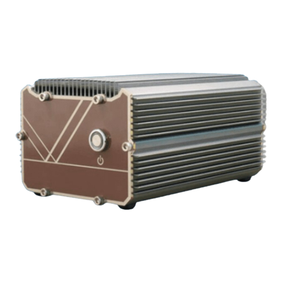
POC-465AWP Series Introduction POC-465AWP is a new segment of Neousys fanless computers featuring an IP66 rating based on Intel® Elkhart Lake Atom. The acronym AWP stands for affordability, waterproof, and protection. In short, the POC-465AWP is designed to solve your everyday environmental challenges. -
Page 11: Specification Of Poc-465Awp
POC-465AWP Series Specification of POC-465AWP System Core ® ® Intel Elkhart Lake Atom x6425E quad-core 2.0GHz/3.0GHz 12W Processor processor ® Graphics Integrated Intel UHD Graphics Memory Up to 32 GB DDR4-3200 SDRAM by one SODIMM socket Supports TPM 2.0 (fTPM/ dTPM) Panel I/O Interface ®... - Page 12 POC-465AWP Series * For wide temperature use condition, a wide temperature/industrial M.2 M key SATA SSD module is required. ** For full function use condition (mini-PCIe and M.2 are all adopted), the operating temperature may be constrained by mini-PCIe and M.2 modules. Please contact Neousys...
-
Page 13: Dimension
POC-465AWP Series Dimension 1.2.1 I/O Panel View 1.2.2 Side View... -
Page 14: Power Button Panel View
POC-465AWP Series 1.2.3 Power Button Panel View 1.2.4 Bottom View... -
Page 15: Wall Mount Bracket Dimensions (Optional)
POC-465AWP Series 1.2.5 Wall Mount Bracket Dimensions (Optional) The system comes with an optional wall mount bracket. -
Page 16: System Overview
POC-465AWP Series System Overview Upon receiving and unpacking your POC-465AWP series, please check immediately if the package contains all the items listed in the following table. If any item(s) are missing or damaged, please contact your local dealer or Neousys Technology. -
Page 17: Poc-465Awp Series Front Panel
POC-465AWP Series POC-465AWP Series Front Panel The IO panel of POC-465AWP features M12 connectors that include an isolated COM, DC input, VGA, Gigabit Ethernet, and USB2.0 ports. Connector Description M12 A-coded COM 1 is isolated RS-232 port with 15 kV ESD protection... -
Page 18: M12 A-Coded Isolated Com Port
POC-465AWP Series 2.2.1 M12 A-coded Isolated COM Port The system provides two isolated COM ports via an M12 A-coded connector for communicating with external devices. COM 1 port is a 3-wire RS-232 specifications and provide up to 115200 bps baud rate while COM2 port is RS-422/485 specifications. -
Page 19: M12 A-Coded Dc-In Port
POC-465AWP Series 2.2.2 M12 A-coded DC-in Port The system accepts a wide range of DC power input from 8V to 35V via a M12 A-coded connector. The M12 A-coded connectors offer COTS availability and ultra-rugged connection reliability when wiring DC power. -
Page 20: M12 X-Coded 2.5Gb Ethernet Port
POC-465AWP Series 2.2.3 M12 X-coded 2.5Gb Ethernet Port The system offers 2.5Gb Ethernet ports using Intel® I226-IT controller via an M12 X-coded, 8-pin connector. Connector Pin Definition Panel side Cable connector end Signal M12 panel M12 cable connector Wire color... -
Page 21: M12 A-Coded Vga Port
POC-465AWP Series 2.2.4 M12 A-coded VGA Port VGA connector is the most common video display connection. The VGA output supports up to 1920x1200@60Hz resolution. To support VGA display output and achieve best VGA output resolution in Windows, you need to install corresponding graphics drivers. - Page 22 POC-465AWP Series VGA Connector Pin Definition Panel side Cable connector end Signal M12 panel side M12 cable connector end Wire color GREEN BLUE P5V_VGA VGA_SDA HSYNC_CN VSYNC_CN VGA_SCL NOTE Please make sure your VGA cable includes SDA and SCL (DDC clock and data) signals for correct communication with monitor to get resolution/timing information.
-
Page 23: M12 A-Coded Usb 2.0 Port
POC-465AWP Series 2.2.5 M12 A-coded USB 2.0 Port The USB2.0 ports are implemented via native xHCI (eXtensible Host Controller Interface) and are backward compatible with USB 1.1 and USB 1.0 devices. UEFI USB support is also provided so you can use USB keyboard/ mouse in UEFI shell environment. -
Page 24: Poc-465Awp Power Button
POC-465AWP Series POC-465AWP Power Button The power button is a non-latched switch for ATX mode on/off operation. Press to turn on the system, PWR LED should light up and to turn off, you can either issue a shutdown command in the OS, or just press the power button. In case of system halts, you can press and hold the power button for 5 seconds to force-shutdown the system. -
Page 25: Poc-465Awp Series Internal I/O
POC-465AWP Series POC-465AWP Series Internal I/O The system’s internal I/O connectors consist of a M.2 2280 M key SATA interface slot, and a full size mini-PCIe slot coupled with a micro SIM soket. 2.4.1 M.2 2280 M Key Slot (SATA Signal Only) The system has an M.2 2280 slot (SATA signal only) for you to install an M.2 SATA... - Page 26 POC-465AWP Series M.2 2280 M Key Pin Definition Pin # Signal Pin # Signal +3V3 +3V3 DAS/DSS_N +3V3 +3V3 +3V3 +3V3 DEVSLP SATA-B+ SATA-B- SATA-A- SATA-A+ PERST N Mechanical Key SUSCLK PEDET +3V3 +3V3 +3V3...
-
Page 27: Mini-Pcie Slot With Micro Sim Socket
POC-465AWP Series 2.4.2 mini-PCIe Slot with micro SIM Socket The system has a mini-PCIe slot coupled with a micro SIM socket. The system provides a mini-PCIe socket (indicated in blue) that is in compliance with mini-PCIe specification rev. 1.2. This mini-PCIe socket is designed with SIM card (slot indicated in red) support. - Page 28 POC-465AWP Series mini-PCIe socket definition Signal (mPCIe) Pin # Signal (mPCIe) WAKE# +3.3Vaux +1.5V CLKREQ# UIM_PWR UIM_DATA REFCLK- UIM_CLK REFCLK+ UIM_RESET UIM_VPP Mechanical Key Reserved* (UIM_C8) Reserved* (UIM_C4) W_DISABLE# PERST# PERn0 3.3V PERp0 +1.5V SMB_CLK PETn0 SMB_DATA PETp0 USB_D- USB_D+ 3.3V...
-
Page 29: System Installation
POC-465AWP Series System Installation Before disassembling the system enclosure and installing components and modules, please make sure you have done the following: ⚫ It is recommended that only qualified service personnel should install and service this product to avoid injury or damage to the system. -
Page 30: Disassembling The System Enclosure
POC-465AWP Series Disassembling the System Enclosure To install necessary components such as memory module, M.2 modules or MezIO module, you need to disassemble the POC-465AWP system enclosure: To disassemble POC-465AWP, turn the system upside down and place it on a... - Page 31 POC-465AWP Series Gently open the bottom panel. Accessible user expansion slots after removing the bottom panel.
-
Page 32: Installing Internal Components
POC-465AWP Series Installing Internal Components 3.2.1 M.2 2280 M Key Module Installation There is one M.2 2280 M key module expansion slot for POC-465AWP system. Please follow the procedures below to install the memory module. Disassemble the system enclosure 2. The M.2 2280 M key slot can be located once the enclosure has been removed. - Page 33 POC-465AWP Series 3. To install the M.2 M key module, you must remove the heatsink first by removing the screws indicated. 4. Remove the M.2 module’s heatink.
- Page 34 POC-465AWP Series 5. Insert the M.2 M key module on a 45 degree angle. 6. Secure the module by fastening the screw.
- Page 35 POC-465AWP Series 7. Remove the protective film off the thernal pad and reinstall the M.2 module’s heatsink to complete the installation. NOTE Please make sure the O-ring is seated properly in the groove to ensure the system’s IP66 functionality. Reinstall the system...
-
Page 36: Mini-Pcie Module & Sim Card Installation
POC-465AWP Series 3.2.2 mini-PCIe Module & SIM Card Installation There is a mini-PCIe slot and micro SIM card socket for POC-465AWP system. Please follow the procedures below for installation. Disassemble the system enclosure. 2. The mini-PCIe slot and micro SIM card socket can be located once the enclosure... - Page 37 POC-465AWP Series 3. Before installing the mini-PCIe module, please install the SIM card first. To install a SIM card, slide the SIM bracket in the direction indicated and lift the bracket. Slide to unlock the bracket Lift the bracket 4. Place the SIM card into the socket, place the bracket over the SIM card, gently press and slide the bracket in the direction shown to secure the SIM card.
-
Page 38: Installing The System Enclosure
POC-465AWP Series Installing the System Enclosure With the system upside down, position on a secured flat surface, place the bottom panel onto the enclosure. NOTE Please make sure the O-ring is seated properly in the groove to ensure the system’s IP66 functionality. -
Page 39: Wall Mount Installation (Optional Accessory)
POC-465AWP Series Wall Mount Installation (Optional Accessory) The optional wall mount bracket allows the system to be mounted horizontally. Please refer to the following installation procedure to install the wall mount. To install the optional wall mount bracket, you need to remove the rubber stands (indicated in blue) at the bottom of the system. - Page 40 POC-465AWP Series Secure the two wall mount brackets (indicated in blue) to the bottom of the system enclosure using the M4 screws (indicated in red) provided. Dimension illustration of the installed wall mount bracket for your reference.
-
Page 41: Powering On The System
POC-465AWP Series Powering On the System There are five methods to power on the system ⚫ Pressing the power button ⚫ Sending a LAN packet via Ethernet (Wake-on-LAN) ⚫ Using the ignition signal input We will describe the processes and actions involved for the first four methods in this section and the ignition signal input method will be described in section 3.7. -
Page 42: Powering On Using Wake-On-Lan
POC-465AWP Series 3.5.2 Powering On Using Wake-on-LAN Wake-on-LAN (WOL) is a mechanism to wake up a computer system from a S3 (standby), S4 (Hibernate) or S5 (system off with standby power) state via issuing Subnet Directed Broadcasts (SDB) or a magic packet. The system implements the Wake-on-LAN function for the GbE port #1 shown below. - Page 43 POC-465AWP Series ⚫ Wake on Magic Packet The system can wake from S3 or S4 state when receiving a magic packet. The magic packet is a broadcast frame containing anywhere within its payload 6 bytes of all 255 (FF FF FF FF FF FF in hexadecimal), followed by sixteen repetitions of the target computer's 48-bit MAC address.
-
Page 44: Ignition Power Control
POC-465AWP Series Ignition Power Control The ignition power control module for in-vehicle applications is a MCU-based implementation that monitors the ignition signal and reacts to turn on/off the system according to predefined on/off delay. Its built-in algorithm supports other features such as ultra-low power standby, battery-low protection, system hard-off, etc. -
Page 45: Additional Features Of Ignition Power Control
POC-465AWP Series 3.6.2 Additional Features of Ignition Power Control In addition to the typical timing correlation, the ignition power control module offers additional features to provide additional reliability for in-vehicle applications. ⚫ Low battery detection The ignition power control module continuously monitors the voltage of DC input when the system is operational. -
Page 46: Wiring Ignition Signal
POC-465AWP Series 3.6.3 Wiring Ignition Signal To have ignition power control for in-vehicle usage, you need to supply IGN signal to the system. The IGN input is located on the Pin 2 of the M12 A-coded connector (shared with DC power input). For in-vehicle ignition control wiring, please do the following: Connect car Battery+ line (12V for sedan, 24V for bus/truck) to V+. -
Page 47: Configure Your Windows System
POC-465AWP Series 3.6.4 Configure your Windows system When applying ignition power control to your system, please make sure you’ve configured your Windows system to initiate a shutdown process when pressing the power button. By default, Windows 10 goes to sleep (S3) mode when power button is pressed. -
Page 48: Bios Settings
POC-465AWP Series BIOS Settings The system is shipped with factory-default BIOS settings optimized for best performance and compatibility. In this section, we’ll illustrate some BIOS settings you may need to set or change prior to operating system installation. Please always make sure you understand the effect of change before you proceed with any changes. -
Page 49: Com Port Configuration
POC-465AWP Series COM Port Configuration The system’s COM1 port supports RS-232. For RS-422/485 communication, the “RS-422/485 Termination” option determines whether to enable/ disable internal termination of RS-422/485 transceiver according to your wiring configuration (e.g. with or without external termination). To set COM1&2 operating mode: Press F2 when the system boots up to enter the BIOS setup utility. -
Page 50: Tpm Availability
POC-465AWP Series 4.1.1 TPM Availability Trusted Platform Module (TPM) is a hardware-based cryptoprocessor to secure hardware by integrating cryptographic keys into devices. The system is designed with on-board TPM 2.0 module. As TPM 2.0 requires 64-bit Windows 10 with UEFI boot mode, it is enabled in BIOS by default. -
Page 51: C-States
POC-465AWP Series C-States C-States is a power-saving technique implemented in modern Intel processors. It shuts down the clock signals and power for idle logic units inside the CPU to save the energy consumed. The trade-off, however, is a longer latency for CPU to wake up and be 100% operational. -
Page 52: Wake-On-Lan
POC-465AWP Series Wake-on-LAN Wake-on-LAN (WOL) is a mechanism which allows you to turn on your system via Ethernet connection. To utilize Wake-on-LAN function, you have to enable this option first in BIOS settings. Please refer to Powering on via Wake-on-LAN function. -
Page 53: Power On After Power Failure
POC-465AWP Series Power On after Power Failure This option defines the system’s behavior when DC power is supplied. Value Description S0 – Power On System is powered on when DC power is supplied. S5 – Power Off System is kept in off state when DC power is supplied. -
Page 54: Ignition Power Control
POC-465AWP Series Ignition Power Control The system feature ignition power control. It monitors the ignition signal and reacts to turn on/off the system according to predefined on/off delay. Its built-in algorithm supports other features such as smart off delay, low battery threshold, system hard-off, etc. - Page 55 POC-465AWP Series For example, highlight [Power On Delay] and press Enter to bring up time delay configuration options. You may also set the input battery voltage to correspond to the voltage supplied by your vehicle by highlighting [Battery Voltage], and press Enter to bring up the options [12v or 24v Battery].
-
Page 56: Position New Boot Device
POC-465AWP Series Position New Boot Device The “Add Boot Options” allow you to determine whether a newly added device (eg. USB flash disk) is to boot as the first device to boot or the last in the boot sequence. To set the newly-installed boot device as the first or last boot device: Press F2 when the system boots up to enter the BIOS setup utility. -
Page 57: Watchdog Timer
POC-465AWP Series Watchdog Timer The watchdog timer secures the boot process by means of a timer. Once the timer expires, a reset command is issued to initiate another booting process. There are two options in BIOS menu, “Automatically after POST” and “Manually after Entering OS”. -
Page 58: Os Support And Driver Installation
OS Support and Driver Installation Operating System Compatibility Due to Intel’s policy, POC-465AWP series only provide driver support for the following Windows operating systems. For Linux support, please use Linux kernel versions no later than 5.15. The following list contains the operating systems which have been tested in Neousys Technology Inc. -
Page 59: Driver Installation
POC-465AWP Series Driver Installation The system drivers are available online, please click on this link to download the drivers. 5.2.1 Install Drivers Automatically Neousys provides a driver package which contain function APIs for Watchdog Timer control function. You should install the driver package (WDT_DIO_Setup.exe) in prior to use these functions. -
Page 60: Appendix A Using Wdt & Dio
In this section, we’ll illustrate how to use the function library provided by Neousys to program the WDT functions. Currently, WDT driver library supports Windows 10 x64 and WOW64 platform. For other OS support, please contact Neousys Technology for further information. -
Page 61: Wdt And Dio Library Installation
POC-465AWP Series WDT and DIO Library Installation To setup WDT & DIO Library, please follow instructions below. 1. Execute WDT_DIO_Setup.2.3.1.9.exe. and the following dialog appears. 2. Click “Next >” and specify the directory of installing related files. The default directory is C:\Neousys\WDT_DIO. - Page 62 POC-465AWP Series 3. Once the installation has finished, a dialog will appear to prompt you to reboot the system. The WDT & DIO library will take effect after the system has rebooted. 4. When programming your WDT or DIO program, the related files are located in...
-
Page 63: Wdt Function Reference
POC-465AWP Series WDT Function Reference InitWDT Syntax BOOL InitWDT(void); Description: Initialize the WDT function. You should always invoke InitWDT() before set or start watchdog timer. Parameter None Return Value TRUE: Successfully initialized FALSE: Failed to initialize Usage BOOL bRet = InitWDT() -
Page 64: Startwdt
POC-465AWP Series StartWDT Syntax BOOL StartWDT(void); Description Starts WDT countdown. Once started, the WDT LED indicator will begin blinking. If ResetWDT() or StopWDT is not invoked before WDT countdowns to 0, the WDT expires and the system resets. Parameter None...
Need help?
Do you have a question about the POC-465AWP Series and is the answer not in the manual?
Questions and answers