Table of Contents
Advertisement
Quick Links
HARBOR BREEZE and logo design are
trademarks or registered trademarks of LF, LLC.
All rights reserved.
Purchase Date
Questions, problems, missing parts? Before returning to your retailer, call our customer
service department at
also contact us at partsplus@lowes.com.
SS22049
888-251-1003, 8 a.m. - 8 p.m., EST, Monday - Sunday. You could
1
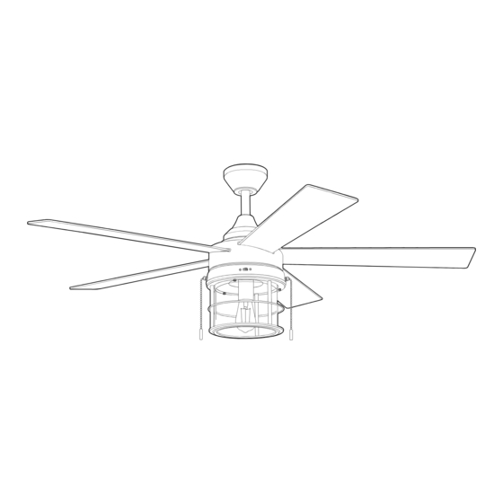
LANDON CEILING FAN
ATTACH YOUR RECEIPT HERE
ITEM #5127874
MODEL #LAN52SS5L
Español p. 19
ADJUNTE SU RECIBO AQUÍ
4007498
APPROVED FOR USE IN
WET LOCATIONS
Advertisement
Table of Contents

Related Manuals for Harbor Breeze LANDON LAN52SS5L


Summary of Contents for Harbor Breeze LANDON LAN52SS5L
- Page 1 ITEM #5127874 LANDON CEILING FAN MODEL #LAN52SS5L HARBOR BREEZE and logo design are trademarks or registered trademarks of LF, LLC. All rights reserved. Español p. 19 ATTACH YOUR RECEIPT HERE ADJUNTE SU RECIBO AQUÍ 4007498 APPROVED FOR USE IN Purchase Date...
-
Page 2: Table Of Contents
TABLE OF CONTENTS Safety Information ..........................2 Package Contents .........................5 Hardware Contents ........................6 Preparation ............................6 Initial Installation ..........................6 Wiring ............................10 Final Installation ..........................12 Operating Instructions .........................15 Care and Maintenance .........................16 Troubleshooting ...........................17 Limited Lifetime Warranty ......................18 Replacement Parts List .......................18 SAFETY INFORMATION CAUTION: Changes or modifications not approved by the party responsible for compliance could void the user's authority to operate the equipment. - Page 3 SAFETY INFORMATION READ AND SAVE THESE INSTRUCTIONS Please read and understand this entire manual before attempting to assemble, install or operate the product. • Do not discard fan carton or foam inserts. Should this fan need to be returned to the factory for repairs, it must be shipped in its original packaging to ensure proper protection against damage that might exceed the initial cause for return.
- Page 4 SAFETY INFORMATION WARNING To reduce the risk of fire or electrical shock, do not use the fan with any solid state speed control device or control fan speed with a full range dimmer switch. To reduce the risk of fire, electrical shock or personal injury, do not bend the blade arms when installing them, balancing the blades or cleaning the fan.
-
Page 5: Package Contents
PACKAGE CONTENTS PART DESCRIPTION QUANTITY PART DESCRIPTION QUANTITY Downrod Light Kit Fitter Canopy Pin (preassembled) Mounting Bracket Clip (preassembled) Motor Housing Bulb Motor Plate Screw Canopy Mounting Screw (preassembled) (preassembled) Switch Housing Canopy Cover Switch Housing Screw Yoke Cover (preassembled) Hanging Ball Cover Blade IMPORTANT: You must use the parts provided... -
Page 6: Hardware Contents
HARDWARE CONTENTS (shown actual size) Wire Rubber Blade Blade Connector Washer Screw Pull Chain Extension Qty. 4 Qty. 15 Qty. 15 + 1 extra + 1 extra Qty. 2 PREPARATION Before beginning assembly of product, make sure all parts are present. Place motor on carpet or on foam to avoid damage to finish. - Page 7 INITIAL INSTALLATION Determine mounting method to use. A. Standard mount B. Angle mount IMPORTANT: If using the angle mount, ensure the ceiling angle is not steeper than 17°. NOTE: Closemount option is not available for this fan. 20° max. *Helpful Hint: Downrod-style mounting is best suited for ceilings 8 ft.
- Page 8 INITIAL INSTALLATION Remove pin (J) and clip (K) from downrod (A). Partially loosen preassembled set screws and nut in motor housing yoke at top of motor housing (D). Set Screw Yoke 6. Insert downrod (A) through canopy (B), canopy cover (N) and yoke cover (O). NOTE: Canopy cover (N) must be turned with the smooth side toward the motor housing (D).
- Page 9 INITIAL INSTALLATION Depending on the length of downrod you use, you may need to cut the lead wires back to simplify the wiring. If you decide to cut back the lead 8 in. wires, it is suggested you do so in the following manner: Hanging Take the lead wires and make sure you have...
-
Page 10: Wiring
INITIAL INSTALLATION Install hanging ball of downrod (A) into opening of mounting bracket (C). Align one of the slots in hanging ball with tab in mounting bracket (C). DANGER: Failure to align one of the slots in the ball with the tab may result in serious injury or death. - Page 11 WIRING Choose wiring diagram (Fig. 1a, Fig. 1b or Fig. 1c) FAN AND LIGHT CONTROLLED BY PULL CHAINS FAN AND LIGHT CONTROLLED BY TWO WALL SWITCHES that fits your situation and make appropriate wiring connections as follows: [IMPORTANT: Use one of 120V POWER the wire connectors (CC) provided to make each FROM CEILING...
-
Page 12: Final Installation
WIRING Wrap electrical tape (not included) around each individual wire connector (CC) down to the wire. WARNING: Make sure no bare wire or wire strands are visible after making connections. Place GREEN and WHITE wire connections on the opposite side of the outlet box from the BLACK and BLUE wire connections. - Page 13 FINAL INSTALLATION DANGER: To reduce the risk of serious bodily injury, DO NOT use power tools to assemble the blades (H). If screws are overtightened, blades (H) may crack and break. Insert the blade (H) through the slot on the band of the motor housing (D).
- Page 14 FINAL INSTALLATION 4. Remove one switch housing screw (G) from posts on the underside of switch housing (F) and partially loosen the other two switch housing screws (G). White Black Connect WHITE wire from switch housing to WHITE wire from light kit fitter (I). Connect BLACK (or BLUE) wire from switch housing (F) to BLUE wire from light Black kit fitter (I).
-
Page 15: Operating Instructions
OPERATING INSTRUCTIONS The fan pull chain, located on the switch housing (F), has four positions to control fan speed. One pull is HIGH, two is MEDIUM, three is LOW and four turns the fan OFF. 2. The light pull chain, located to the left of the reverse switch, is used to turn the light ON or OFF. -
Page 16: Care And Maintenance
OPERATING INSTRUCTIONS 3A. In warmer weather, setting the reverse switch in the LEFT position will result in downward airflow creating a wind chill effect. 3B. In cooler weather, setting the reverse switch in the RIGHT position will result in upward airflow that can help move stagnant, hot air off the ceiling area. -
Page 17: Troubleshooting
TROUBLESHOOTING WARNING: Before beginning work, shut off the power supply to avoid electrical shock. PROBLEM POSSIBLE CAUSE CORRECTIVE ACTION Fan does not move. 1. Reverse switch not engaged. 1. Push switch firmly either left or right. 2. Power is off or fuse is blown. 2. -
Page 18: Limited Lifetime Warranty
LIMITED LIFETIME WARRANTY The distributor warrants this fan to be free from defects in workmanship and materials present at time of shipment from the factory for Lifetime limited from the date of purchase. This warranty applies only to the original purchaser. The distributor agrees to correct any defect at no charge or, at our option, replace the ceiling fan with a comparable or superior model.
Need help?
Do you have a question about the LANDON LAN52SS5L and is the answer not in the manual?
Questions and answers
what is the highest watt bulb I can use with fan #5127874 ?