Table of Contents
Advertisement
Available languages
Available languages
Harbor Breeze® is a registered trademark
of LF, LLC. All Rights Reserved.
ATTACH YOUR RECEIPT HERE
Serial Number
Questions, problems, missing parts? Before returning to your retailer, call our customer
service department at 1-800-643-0067, 8 a.m. - 6 p.m., EST, Monday - Thursday and
8 a.m. - 5 p.m., EST, Friday.
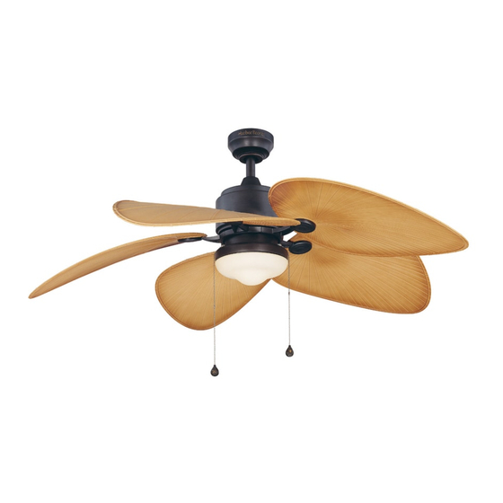
FREEPORT CEILING FAN
Purchase Date
ITEM #0068717
MODEL #LP8072LAZ
Español p. 22
Advertisement
Chapters
Table of Contents

Subscribe to Our Youtube Channel
Related Manuals for Harbor Breeze LP8072LAZ


Summary of Contents for Harbor Breeze LP8072LAZ
- Page 1 ITEM #0068717 FREEPORT CEILING FAN MODEL #LP8072LAZ Harbor Breeze® is a registered trademark of LF, LLC. All Rights Reserved. Español p. 22 ATTACH YOUR RECEIPT HERE Serial Number Purchase Date Questions, problems, missing parts? Before returning to your retailer, call our customer service department at 1-800-643-0067, 8 a.m.
-
Page 2: Table Of Contents
TABLE OF CONTENTS Safety Information ......................... Package Contents ......................... Hardware Contents ........................Preparation ........................... Assembly Instructions ........................Hanging Instructions ........................Wiring Instructions ........................Canopy Housing Installation ......................Blade Installation .......................... Light Kit Fitter Assembly Installation ..................... Pull Chain Operating Instructions ....................Blade Balancing Installation Instructions .................. -
Page 3: Safety Information
SAFETY INFORMATION Please read and understand this entire manual before attempting to assemble, operate or install the product. If you have any questions regarding the product, please call customer service at 1-800-643-0067, 8 a.m. - 6 p.m., EST, Monday - Thursday and 8 a.m. - 5 p.m., EST, Friday. •... - Page 4 SAFETY INFORMATION (Continued) WARNING This fan is to be used in dry or damp locations only. •The net weight of this fan is: 23.1 lbs. (10.5 kg).
-
Page 5: Package Contents
PACKAGE CONTENTS PART DESCRIPTION QUANTITY PART DESCRIPTION QUANTITY Motor Assembly Glass Hanger Bracket Blade Downrod/Hanger Ball Assembly Ceiling Canopy Canopy Screw Cover Motor Coupling Cover Light Kit Fitter Assembly Bulb Blade Holder Arm Socket Plate Assembly... -
Page 6: Hardware Contents
HARDWARE CONTENTS (shown actual size) Fiber Washer-Head Wire Washers Screws Screws Connectors Qty. 11 Fan Chain Light Kit Chain Qty. 4 Qty. 11 Qty. 11 Balance Coupler Coupler (not shown Qty. 1 Qty. 1 to size) Qty. 1 PREPARATION Before beginning assembly of product, make sure all parts are present. Compare parts with. package contents list and diagram above. -
Page 7: Assembly Instructions
ASSEMBLY INSTRUCTIONS 1. Remove the hanger ball portion from the downrod/hanger ball assembly (C) by loosen- ing the set screw in the hanger ball until the ball falls freely down the downrod. Remove the pin from the downrod, then remove the hanger ball. - Page 8 ASSEMBLY INSTRUCTIONS (Continued) 4. Route wires through motor coupling cover (F), canopy screw cover (E) and ceiling canopy (D). (Fig. 4) 5. Reinstall the hanger ball on the downrod/hanger ball assembly (C) by routing the three 54 in. wires through the hanger ball. Position the pin from the downrod/hanger ball assembly (C) through the two holes in the downrod and align the hanger ball so the pin is...
-
Page 9: Hanging Instructions
HANGING INSTRUCTIONS WARNING To avoid possible electrical shock, be sure electricity is turned off at the main fuse box before hanging. NOTE: If you are not sure if the outlet box is grounded, contact a licensed electrician for advice, as it must be grounded for safe opertion. WARNING The fan must be hung with at least 7 ft. -
Page 10: Wiring Instructions
WIRING INSTRUCTIONS WARNING To avoid possible electrical shock, be sure electricity is turned off at the main fuse box before hanging. NOTE: If you are not sure if the outlet box is grounded, contact a licensed electrician for advice, as it must be grounded for safe opertion. 1. -
Page 11: Canopy Housing Installation
CANOPY HOUSING INSTALLATION 1. Remove one of the two shoulder screws in the hanger bracket (B). Loosen the second shoulder screw without fully removing it. Assemble ceiling canopy (D) by rotating key slot over shoulder screw in hanger bracket (B). Tighten shoulder screw. -
Page 12: Light Kit Fitter Assembly Installation
BLADE INSTALLATION (Continued) 2. Position the blade (L) over the blade holder arm (I) with threaded posts showing. Make sure the bottom edge of the blade (L) is fully seated against the blade holder arm (I). Tighten washer-head screws (BB) with fiber washers (CC) to secure the blade (L) to the blade holder arm (I). - Page 13 LIGHT KIT FITTER ASSEMBLY INSTALLATION (Continued) 2. Securely attach the 9-pin connector from the motor assembly (A) to the wire harness socket within the light kit fitter assembly (G). (Fig. 2) 3. Securely attach the two single-pin down light connector from the light kit fitter assembly (G) to the socket plate assembly (J).
-
Page 14: Pull Chain Operating Instructions
LIGHT KIT FITTER ASSEMBLY INSTALLATION (Continued) 5. Install bulb (H). (Fig. 5) CAUTION Bulb is pressurized and may shatter. DO NOT TOUCH BULB WITH BARE HANDS. Fingerprints may result in shorter bulb life. Remove fingerprints with alcohol prior to use. To reduce the risk of fire, use 100-watt max. - Page 15 PULL CHAIN OPERATING INSTRUCTIONS (Continued) 2. Install the fan chain coupler (EE) and light kit chain coupler (FF). (Fig. 2) 3. Check the operation of the fan by gently pulling on the fan chain coupler (EE). (Fig. 3) Fan Pull Chain Operating Sequence Pull High Medium...
- Page 16 PULL CHAIN OPERATING INSTRUCTIONS (Continued) 5. Check the operation of the light by gently pulling on the light kit chain coupler (FF). (Fig. 5) Light Kit Pull Chain Operating Sequence Pull Pull...
-
Page 17: Blade Balancing Installation Instructions
BLADE BALANCING INSTALLATION INSTRUCTIONS WARNING The balancing clip must always be firmly pushed onto the blade till it touches the edge of the blade. Failure to do so could allow clip to fly off and cause personal injury. 1. Interchanging positions of adjacent blades (L) can redistribute the weight and result in a smoother operation. -
Page 18: Care And Maintenance
CARE AND MAINTENANCE •When cleaning, use only a soft brush or lint-free cloth to avoid scratching the finish. •Abrasive cleaning agents are not required and should be avoided to prevent damage to finish. WARNING Do not use water when cleaning your ceiling fan. It could damage the motor or the finish and create the possibility of electrical shock. - Page 19 TROUBLESHOOTING (Continued) PROBLEM POSSIBLE CAUSE CORRECTIVE ACTION 4. Wire connectors inside 4. Check to make sure wire connectors in Fan sounds housing rattling. switch housing are not rattling against noisy each other or against the interior wall of the switch housing. WARNING Make sure main power is turned off! 5.
-
Page 20: Warranty
WARRANTY The manufacturer warrants this fan to be free from defects in workmanship and material present at time of shipment from the factory for life (with limitations) from the date of purchase. This warranty applies only to the original purchaser. The manufacturer agrees to correct such defect at no change or at our option replace the ceiling fan with a comparable or superior model. -
Page 21: Replacement Parts List
REPLACEMENT PARTS LIST For replacement parts, call our customer service department at 1-800-643-0067, 8 a.m. - 6 p.m., EST, Monday - Thursday and 8 a.m. - 5 p.m., EST, Friday. PART DESCRIPTION PART # Motor Assembly AMA8072LAZ Hanger Bracket (with Screws) APGAC110RBL Hanger Ball/Downrod Assembly ADRACT1-45LAZ... - Page 22 ARTÍCULO #0068717 VENTILADOR DE TECHO FREEPORT MODELO #LP8072LAZ Harbor Breeze® es una marca registrada de LF, LLC. Todos los derechos reservados. Adjuntar su recibo AQUÍ Número de serie Fecha de Compra ¿Preguntas, problemas, piezas faltantes? Antes de volver a la tienda, llame a nuestro Departamento de Servicio al Cliente al 1-800-643-0067, de lunes a jueves de 8 a.m.
- Page 23 ÍNDICE Información de seguridad ......................Contenido del paquete ......................... Aditamentos ..........................Preparación ..........................Instrucciones de ensamblaje ......................Instrucciones para colgar ......................Instrucciones de cableado ......................Instalación de la carcasa de la base .................... Instalación de las aspas ....................... Instalación del ensamble del soporte del kit de iluminación ............Instrucciones de funcionamiento de la cadena del tirador ............
-
Page 24: Información De Seguridad
INFORMACIÓN DE SEGURIDAD Lea y comprenda completamente este manual antes de intentar ensamblar, usar o instalar el producto. Si tiene preguntas relacionadas con el producto, llame a nuestro Departamento de Servicio al Cliente al 1-800-643-0067, de lunes a jueves de 8 a.m. a 6 p.m. y los viernes de 8 a.m. - Page 25 INFORMACIÓN DE SEGURIDAD (Continuación) ADVERTENCIA Para reducir el riesgo de incendios, descargas eléctricas o lesiones personales, no doble los brazos de las aspas al instalarlas, al equilibrarlas o al limpiar el ventilador. No introduzca objetos extraños entre las aspas en movimiento. Instale en una caja de salida marcada como “ACCEPTABLE FOR FAN SUPPORT”...
-
Page 26: Contenido Del Paquete
CONTENIDO DEL PAQUETE PIEZA DESCRIPCIÓN CANTIDAD PIEZA DESCRIPCIÓN CANTIDAD Ensamble del motor Vidrio Abrazadera para colgar Aspa Ensamble de la bola para colgar/varilla Escudo del techo Cubierta para los tornillo de la base Cubierta para el acoplador del motor Ensamble del soporte del kit de iluminación Bombilla Brazo de soporte del aspa... -
Page 27: Aditamentos
ADITAMENTOS (Se muestra en tamaño real) Arandelas Tornillos con de fibra Conectores cabeza de Tornillos de cable arandela Cant. 11 Acoplador de Acoplador de Cant. 11 Cant. 4 Cant. 11 Kit de equilibrio la cadena la cadena (no se muestra del ventilador del kit de en tamaño real) -
Page 28: Instrucciones De Ensamblaje
INSTRUCCIONES DE ENSAMBLAJE 1. Retire la parte correspondiente a la bola para colgar del ensamble de la bola para colgar/varilla(C) aflojando el tornillo de fijación de la bola hasta que ésta salga libremente de la varilla. Retire el pasador de la varilla y luego retire la bola para colgar. - Page 29 INSTRUCCIONES DE ENSAMBLAJE (Continuación) 4. Pase los cables a través de la cubierta del acoplador del motor (F), la cubierta del tornillo de la base (E) y la base para techo (D). (Fig. 4) 5. Vuelva a instalar la bola para colgar en el ensamble de la bola para colgar/varilla (C) haciendo pasar los tres conductores de 1,37 m a través de la bola para colgar.
-
Page 30: Instrucciones Para Colgar
INSTRUCCIONES PARA COLGAR ADVERTENCIA Para evitar una posible descarga eléctrica,asegúrese de cortar la alimentación eléctrica de la caja de fusibles principal antes de colgar el ventilador. NOTA: Si no está seguro de si la caja de salida tiene conexión a tierra, pida consejo a un electricista certificado, ya que debe tener conexión a tierra para un funcionamiento seguro. -
Page 31: Instrucciones De Cableado
INSTRUCCIONES DE CABLEADO ADVERTENCIA Para evitar una posible descarga eléctrica,asegúrese de cortar la alimentación eléctrica de la caja de fusibles principal antes de colgar el ventilador. NOTA: Si no está seguro de si la caja de salida tiene conexión a tierra, pida consejo a un electricista certificado, ya que debe tener conexión a tierra para un funcionamiento seguro. -
Page 32: Instalación De La Carcasa De La Base
INSTALACIÓN DE LA CARCASA DE LA BASE 1. Retire uno de los dos tornillos de reborde de la abrazadera para colgar. Afloje el segundo tornillo de reborde sin retirarlo del todo. Ensamble la base de techo (D) girando el chavetero de la base (E) sobre el tornillo de reborde de la abrazadera para colgar (B). -
Page 33: Instalación Del Ensamble Del Soporte Del Kit De Iluminación
INSTALACIÓN DE LAS ASPAS (Continuación) 2. Coloque las aspas (L) sobre sus soportes (I) con los postes roscados que se muestran. Asegúrese de que el borde inferior del aspa (L) esté completamente asentado sobre el brazo del aspa. Ajuste los tornillos con cabeza (BB) junto con las arandelas de fibra (CC) para asegurar las aspas(L) a los brazos del aspa (I). - Page 34 INSTALACIÓN DEL ENSAMBLE DEL SOPORTE DEL KIT DE ILUMINACIÓN (Continuación) 2. Fije firmemente el conector de 9 clavijas del ensamble del motor (A) al portalámparas con arnés de cableado que se encuentra dentro del ensamble del soporte del kit de iluminación (G).
-
Page 35: Instrucciones De Funcionamiento De La Cadena Del Tirador
INSTALACIÓN DEL ENSAMBLE DEL SOPORTE DEL KIT DE ILUMINACIÓN (Continuación) 5. Instale la bombilla (H). (Fig. 5) PRECAUCIÓN La bombilla está presurizada y puede quebrarse. NO TOQUE LA BOMBILLA CON LAS MANOS DESPROTEGIDAS. Las huellas dactilares en la bombilla pueden reducir la vida útil de la misma. - Page 36 INSTRUCCIONES DE FUNCIONAMIENTO DE LA CADENA DEL TIRADOR (Continuación) 2. Instale el acoplador de la cadena del ventilador (EE) y el acoplador de la cadena del kit de iluminación (FF). (Fig. 2) 3. Verifique el funcionamiento del ventilador jalando suavemente del acoplador de la cadena del ventilador (EE).
- Page 37 INSTRUCCIONES DE FUNCIONAMIENTO DE LA CADENA DEL TIRADOR (Continuación) 5. Verifique el funcionamiento de la luz jalando suavemente del acoplados de la cadena del kit de iluminación (FF). (Fig. 5) Secuencia de funcionamiento de la cadenilla del kit de iluminación 1.ª...
-
Page 38: Instrucciones De Instalación De Aspa Equilibrada
INSTRUCCIONES DE INSTALACIÓN DE ASPA EQUILIBRADA ADVERTENCIA El sujetador de equilibrio siempre se debe empujar firmemente en el aspa hasta que toque el borde de ésta. Si no lo hace, el sujetador puede salir disparado y causar daños personales. 1. Intercambiar la posición de aspas adyacentes (L) puede redistribuir el peso y hacer que funcione más suavemente. -
Page 39: Cuidado Y Mantenimiento
CUIDADO Y MANTENIMIENTO •Use sólo una brocha suave o un paño sin pelusas para evitar rayar el acabado al limpiarlas. •Los agentes limpiadores abrasivos son innecesarios y deben evitarse para no dañar el acabado. ADVERTENCIA No use agua para limpiar el ventilador de techo. Puede dañar el motor o el acabado y crea la posibilidad de una descarga eléctrica. - Page 40 SOLUCIÓN DE PROBLEMAS (Continuación) PROBLEMA CAUSA POSIBLE ACCIÓN CORRECTIVA El ventilador 4. Los conectores de cable de la 4. Compruebe que los conectores de carcasa repiquetean. cable de la carcasa del interruptor no emite mucho repiqueteen unos contra otros o contra ruido las paredes interiores de la carcasa del (Continuación)
-
Page 41: Garantía
GARANTÍA El fabricante garantiza, de por vida, (con limitaciones) que este ventilador no presenta defectos ni de fabricación ni en los materiales presentes en el momento del transporte desde la fábrica a partir de la fecha de compra. Esta garantía es válida sólo para el comprador original. El fabricante acepta reparar dichos defectos sin cargo o, según nuestro criterio, reemplazar el ventilador de techo por un modelo comparable o superior. -
Page 42: Lista De Piezas De Repuesto
LISTA DE PIEZAS DE REPUESTO Para obtener piezas de repuesto, llame a nuestro Departamento de Servicio al Cliente al 1-800-643- 0067, de lunes a jueves de 8 a.m. a 6 p.m. y los viernes de 8 a.m. a 5 p.m., hora estándar del Este. PIEZA DESCRIPCIÓN PIEZA #...
Need help?
Do you have a question about the LP8072LAZ and is the answer not in the manual?
Questions and answers