Table of Contents
Advertisement
Quick Links
Cover
Renesas Solution Starter Kit
Motor Control Evaluation System
16
- Motor Control IC: RAJ306102 -
All information contained in these materials, including products and product specifications,
represents information on the product at the time of publication and is subject to change by
Renesas Electronics Corp. without notice. Please review the latest information published by
Renesas Electronics Corp. through various means, including the Renesas Electronics Corp.
website (http://www.renesas.com).
RAJ306102 RSSK User's Manual
Rev.1.00 Nov 2023
Advertisement
Table of Contents

Subscribe to Our Youtube Channel
Related Manuals for Renesas RAJ306102


Summary of Contents for Renesas RAJ306102
- Page 1 All information contained in these materials, including products and product specifications, represents information on the product at the time of publication and is subject to change by Renesas Electronics Corp. without notice. Please review the latest information published by Renesas Electronics Corp. through various means, including the Renesas Electronics Corp.
- Page 2 Renesas Electronics disclaims any and all liability for any damages or losses incurred by you or any third parties arising from the use of any Renesas Electronics product that is inconsistent with any Renesas Electronics data sheet, user’s manual or other Renesas Electronics document.
- Page 3 Products The following usage notes are applicable to all Microprocessing unit and Microcontroller unit products from Renesas. For detailed usage notes on the products covered by this document, refer to the relevant sections of the document as well as any technical updates that have been issued for the products.
- Page 4 For Your Safety Do not fail to read this manual before using the RAJ306012 Renesas Solution Starter Kit ( RTK0EML2J0S00020BJ ) (this product). • Follow the indications in this manual when using the product. • Keep this manual near the product so you can refer to it whenever necessary.
- Page 5 • Marks directing that the specified action is required. Example: Turn Off (Disconnect) Power Supply! General Instruction Instructs the user to turn off (disconnect) the The specified action is required. power supply to the product. © 2023 Renesas Electronics Corporation. All rights reserved.
- Page 6 • The product has no safety case. • Failure to observe the above could cause fire, electric shock, burns, or malfunction. • The product may not perform as expected if used for other than its intended purpose. © 2023 Renesas Electronics Corporation. All rights reserved.
- Page 7 Follow the procedure specified in the manual when powering the system on or off. • Failure to do so could cause overheating or malfunction. Caution – Static Electricity • Use the antistatic band. Failure to do so could cause malfunction or unstable motion. © 2023 Renesas Electronics Corporation. All rights reserved.
-
Page 8: Table Of Contents
CONTENTS CONTENTS ................................1 Chapter 1. Overview ............................. 1 Feature ..............................3 Chapter 2. Product Specifications ........................4 Outline ..............................4 Evaluation Board..........................5 2.2.1 Appearance..........................6 Block Diagram..........................7 2.2.2 2.2.3 Pin Assignment and Connection on Evaluation Board ..............8 2.2.3 Main Parts, Terminals, and Connectors .................. - Page 9 Program Write ............................ 49 5.1.1 studio ............................50 5.1.2 CS+ ............................51 5.1.3 Renesas Flash Programmer ...................... 52 Chapter 6. Renesas Motor Workbench ......................53 Chapter 7. Information ............................54 European Union Regulatory Notices ....................54 Revision History ..............................55 Index-2...
-
Page 10: Contents
[RTK0EML2J0S00020BJ] (now referred to as RAJ306102 RSSK) is an evaluation kit for the RAJ306102. The RAJ306102 is a motor control IC consisting of the RL78/G1F (R5F11BLEGFB) and a smart gate driver (RAA306012). The RAJ306102 evaluation board included in the evaluation kit enables motor control by inverter operation. - Page 11 The 0[Ω] resisters are used to change the connection, 1005[mm] or 1608[mm] size registers are available (solder shorts are available too) Note.1 USB cable for connecting with PC is necessary to use Renesas Motor Workbench or IDE. Abbreviations Abbreviations Full Name...
-
Page 12: Feature
RAJ306102 Sample programs download website: https://www.renesas.com/RTK0EML2J0S00020BJ Support Renesas Motor Workbench tool. Renesas Motor Workbench is a tool for monitoring and changing global variables in operation from a PC. For details of the features and instructions on using the tool, refer to Renesas website. R12UZ0130EJ0100 Rev.1.00... -
Page 13: Chapter 2. Product Specifications
MOSFET TPH12008NH (80[V], 24[A]) Sensor Hall sensor or sensorless ・ USB for E2 Lite (E2OB) ・ USB for Renesas Motor WorkBench (Now referred to as RMWB) ・ External MOSFET connector (CN_EXT_MOS) Note.1 ・ Hall sensor signal input connector (CN_HALL) Note.2 ・... -
Page 14: Evaluation Board
Wave viewer tool The latest tool can be received from Renesas website Note.1: The maximum VM rating of the RAJ306102 is 65[V], but due to the Low Voltage Directive (LVD), this kit supports a maximum VM of 48[V]. Note.2: The Evaluation Board has through holes for mounting the connector. When using this function, please mount the connector. -
Page 15: Appearance
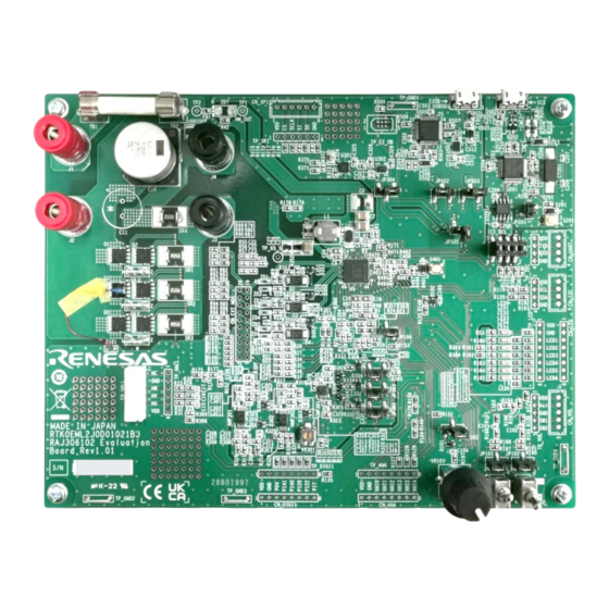
RAJ306102 RSSK User’s Manual Chapter 2. Product Specifications 2.2.1 Appearance Figure 2-1 Appearance R12UZ0130EJ0100 Rev.1.00 Page 6 of 55 Nov 1, 2023... -
Page 16: Block Diagram
RAJ306102 RSSK User’s Manual Chapter 2. Product Specifications 2.2.2 Block Diagram USB_5p0V Ferrite EX_LDO_5p0V Fuse Power Source External bead EX_LDO_SEL UVCC J1: Power 5.0[V] LDO ET_LDO_3p3V J4: GND E2OB AGND USB Connector 5p0V External (DC: 24[V]) (E2_LITE) (ICS) 3.3[V] LDO... -
Page 17: Pin Assignment And Connection On Evaluation Board
RAJ306102 RSSK User’s Manual Chapter 2. Product Specifications 2.2.3 Pin Assignment and Connection on Evaluation Board Table 2-3 Pin Assignments and Connection on Evaluation Board Pin No. RAJ306102 Connection on Evaluation Board Note P02/TxD1 ICS/CN_UART_2 LED1/CN_LED_3 LED2/CN_LED_4 P141 CN_DIGI1_4 P140... - Page 18 RAJ306102 RSSK User’s Manual Chapter 2. Product Specifications Pin No. RAJ306102 Connection on Evaluation Board Note AGND AGND FBLDO ─ VCC5V MVDD P25/ANI5/DA3O CN_ANA_7 P24/ANI4 CN_ANA_8/IV_COM P23/ANI3 VR101/CN_ANA_6/(CN_VOL_2) P22/ANI2 CN_ANA_5/IW_COM P21/ANI1 CN_ANA_4/VBRIDGE_VOL P20/ANI0 CN_ANA_3/IU_COM CN_DIGI1_3 P03/RxD1 ICS/CN_UART_3 ─ EPAD PGND R12UZ0130EJ0100 Rev.1.00...
-
Page 19: Main Parts, Terminals, And Connectors
RAJ306102 RSSK User’s Manual Chapter 2. Product Specifications 2.2.4 Main Parts, Terminals, and Connectors The Main Parts, Terminals, and Connectors on the Evaluation Board are in the layout as follows. USB (ICS) USB (E2OB) E2OB Fuse EX_LDO_SEL MOSFET RMWB (ICS) - Page 20 RAJ306102 RSSK User’s Manual Chapter 2. Product Specifications Universal area CN_SPI Spare circuit CN_UART CN_I2C CN_LED CN_EXT_MOS CN_VOL CN_DIGI1 CN_ANA Universal area Figure 2-4 Unmounted Connectors and Other Circuits Table 2-5 Unmounted Connectors and Other Circuits List Parts Name Item...
-
Page 21: Motor [Tg-55L-Ka 24V (Tsukasa Electric Co., Ltd)]
RAJ306102 RSSK User’s Manual Chapter 2. Product Specifications Motor [TG-55L-KA 24V (TSUKASA ELECTRIC CO., LTD)] Table 2-6 shows the specification of the attached motor. For the details of the motor specifications, refer to TSUKASA ELECTRIC website. Table 2-6 TG-55L-KA 24V Motor Specification... -
Page 22: Ferrite Core [E04Sr200932 (Seiwa Electric Mfg.)]
RAJ306102 RSSK User’s Manual Chapter 2. Product Specifications Ferrite Core [E04SR200932 (SEIWA ELECTRIC MFG.)] The RAJ306102 RSSK includes a ferrite core to comply with the EMC Directive. Please use the ferrite core with 2 turns as necessary. Figure 2-6 Ferrite Core R12UZ0130EJ0100 Rev.1.00... -
Page 23: Chapter 3. Usage
Chapter 3. Usage Chapter 3. Usage The RAJ306102 RSSK is available for evaluation with some kinds of motor control methods by using the Evaluation Board, and Motor attached in this evaluation kit. This evaluation kit includes the following can be evaluated for two different control methods with sample programs. -
Page 24: Factory Default Setting
Evaluation Board, and motors that make up the kit. Refer to Figure 3-2 Setting of RAJ306102 RSSK for Motor Evaluation for details on the evaluation method. To evaluate other motor control methods, it is necessary to change the wiring of the Evaluation Board and the... - Page 25 Setting of Need to change Sample program of Sample program of Sample program for Evaluation Board Evaluation Board (Default settings) Evaluation Board Figure 3-2 Setting of RAJ306102 RSSK for Motor Evaluation R12UZ0130EJ0100 Rev.1.00 Page 16 of 55 Nov 1, 2023...
-
Page 26: 120-Degree Conducting Control Using Hall Sensors
Table 3-1 shows the control specifications. For details of the specifics of the program, please refer to the Application Note “120-degree conducting control of permanent magnetic synchronous motor (Implementation) (R18AN0062EJ)” of RAJ306102. Table 3-1 Basic Specifications of 120-degree Conducting Control Using Hall Sensors Software... -
Page 27: Board Settings
RAJ306102 RSSK User’s Manual Chapter 3. Usage 3.2.2 Board Settings In the 120-degree conducting control using Hall sensors, the motor position is detected by the external Hall sensors and the Hall signals are input to the general-purpose comparators of the smart gate driver. -
Page 28: Operation Guide
Hall sensors control requires the connections of Hall signals.) c. Connect the power source and the Evaluation Board. (Do not supply power at this time.) The RAJ306102 RSSK includes a ferrite core to comply with the EMC Directive. Please use the ferrite core with 2 turns as necessary. - Page 29 RAJ306102 RSSK User’s Manual Chapter 3. Usage 3.2.3.2 Initial Setting Set the toggle switches (SW101, SW102) to Low and set the potentiometer (VR101) to center. (The state in which the knob mark is directly above the knob is called center. The potentiometer used on this board has a pivot point in the center position.)
- Page 30 RAJ306102 RSSK User’s Manual Chapter 3. Usage 3.2.3.3 Power Supply Supply DC 24[V] to Evaluation Board. The LED0 lights up when power is supplied. Power Source (Output: On) DC 24[V]/2[A] limit Evaluation Board LED0 LED1 LED2 LED3 LED4 LED5 LED6...
- Page 31 RAJ306102 RSSK User’s Manual Chapter 3. Usage 3.2.3.4 Motor Operation Set SW101 to High and turn the potentiometer (VR101). The motor rotates in the direction in which the potentiometer (VR101) is turned, according to the amount of turning. The LEDs lights up according to the control.
- Page 32 RAJ306102 RSSK User’s Manual Chapter 3. Usage 3.2.3.5 Stop Motor Operation To stop the motor, return the potentiometer (VR101) to the center and set SW101 to Low. Power Source (Output: On) DC 24[V]/2[A] limit Evaluation Board LED0 LED1 LED2 LED3...
- Page 33 RAJ306102 RSSK User’s Manual Chapter 3. Usage 3.2.3.6 Stop Power Supply Stop the power supply. Power Source (Output: Off) DC 24[V]/2[A] limit Evaluation Board LED0 LED1 LED2 LED3 LED4 LED5 LED6 High Figure 3-9 Stop Power Supply R12UZ0130EJ0100 Rev.1.00 Page 24 of 55...
-
Page 34: Sensorless 120-Degree Conducting Control
Table 3-2 show the control specifications. For details of the specifics of the program, please refer to the Application Note "120-degree conducting control of permanent magnetic synchronous motor (Implementation) (R18AN0062EJ)" of RAJ306102. Table 3-2 Basic Specifications of Sensorless 120-degree Conducting Control Software... -
Page 35: Board Settings
RAJ306102 RSSK User’s Manual Chapter 3. Usage 3.3.2 Board Settings In the sensorless 120-degree conducting control, the motor position is detected by zero-crossing of the inductive voltage (BEMF). The inductive voltage (BEMF) can be sensed by input the phase voltages to the differential amplifiers or BEMF sense amplifier of the smart gate driver. -
Page 36: Operation Guide
Hall signals.) c. Connect the power source and the Evaluation Board. (Do not supply power at this time.) The RAJ306102 RSSK includes a ferrite core to comply with the EMC Directive. Please use the ferrite core with 2 turns as necessary. - Page 37 RAJ306102 RSSK User’s Manual Chapter 3. Usage 3.3.3.2 Initial Setting Set the toggle switches (SW101, SW102) to Low and set the potentiometer (VR101) to center. (The state in which the knob mark is directly above the knob is called center. The potentiometer used on this board has a pivot point in the center position.)
- Page 38 RAJ306102 RSSK User’s Manual Chapter 3. Usage 3.3.3.3 Power Supply Supply DC 24[V] to Evaluation Board by connecting the power source. The LED0 lights up when power is supplied. Power Source (Output: On) DC 24[V]/2[A] limit Evaluation Board LED0 LED1...
-
Page 39: Motor Operation
RAJ306102 RSSK User’s Manual Chapter 3. Usage 3.3.3.4 Motor Operation Set SW101 to High and turn the potentiometer (VR101). The motor rotates in the direction in which the potentiometer (VR101) is turned, according to the amount of turning. The LEDs lights up according to the control. - Page 40 RAJ306102 RSSK User’s Manual Chapter 3. Usage 3.3.3.5 Stop Motor Operation To stop the motor, return the potentiometer (VR101) to the center and set SW101 to Low. Power Source (Output: On) DC 24[V]/2[A] limit Evaluation Board LED0 LED1 LED2 LED3...
- Page 41 RAJ306102 RSSK User’s Manual Chapter 3. Usage 3.3.3.6 Stop Power Supply Stop the power supply. Power Source (Output: Off) DC 24[V]/2[A] limit Evaluation Board LED0 LED1 LED2 LED3 LED4 LED5 LED6 High Figure 3-16 Stop Power Supply R12UZ0130EJ0100 Rev.1.00 Page 32 of 55...
-
Page 42: Chapter 4. Peripheral Circuits
4.3.4 Motor and supply the voltage according to the motor within the operating range of RAJ306102. In addition, a fuse is mounted between TB1 and TB2 of Evaluation Board. Replace the fuse capacity according to the motor drive current. When using external MOSFET board and shunt resistor mounted on the Evaluation Board, refer to 4.3.1.1 MOSFET and connect the external MOSFET board power... -
Page 43: Peripheral Circuit Power Supply (Vdd(3.3[V]) Or Vcc5V(5.0[V]))
(R4 / R5) of the external feedback resistors shown in Figure 4-2. These resistances on the Evaluation Board are R4 = 160[kΩ] and R5 = 91[kΩ], so the output voltage of the VDD pin is 3.310[V]. For details of VDD pin and VCC5V pin, refer to 5.1.2 in the "RAJ306102 User’s Manual: Hardware (R18UZ0082EJ)". -
Page 44: Motor Drive Circuit
RAJ306102 RSSK User’s Manual Chapter 4. Peripheral Circuits Motor Drive Circuit The Evaluation Board has MOSFETs, shunt resistors, and a thermistor for the MOSFET as a motor drive circuit. Also, it is possible to connect the external MOSFET board to CN_EXT_MOS (external MOSFET connector). - Page 45 RAJ306102 RSSK User’s Manual Chapter 4. Peripheral Circuits Table 4-2 External MOSFET Connector (CN_EXT_MOS) Pin Assignment Connector Terminal No. Terminal Function RAJ306102 Port CN_EXT_MOS P23/ANI3 (IW), WIN (DA3N) P25/ANI5 (DA3O) P23/ANI3 (IW), WIP (DA3P) P25/ANI5 (DA3O) P24/ANI4 (IV), VIN (DA2N)
-
Page 46: Half-Bridges
RAJ306102 RSSK User’s Manual Chapter 4. Peripheral Circuits 4.3.1 Half-Bridges The Evaluation Board has inverter control circuit consisting of six MOSFETs for motor control. The MCU controls the MOSFETs through the smart gate driver by using six timer output functions. In addition, the bus... - Page 47 RAJ306102 RSSK User’s Manual Chapter 4. Peripheral Circuits 4.3.1.1 MOSFET The Evaluation Board has MOSFETs for the motor drive. It is also possible to connect external MOSFET board to CN_EXT_MOS (external MOSFET connector). The default setting of Evaluation Board has a 0[Ω] resistors mounted on the MOSFET connection selection resistors (R79-R87), so the MOSFET mounted on the Evaluation Board is enabled.
- Page 48 The overcurrent detection signal OC# is High when the shunt current value is within the threshold range and Low when an overcurrent is detected. Therefore, as long as the MOSFETs and RAJ306102 are not broken, the Evaluation Board and the motor are protectable by monitoring the overcurrent detection signal OC# and forcing the timer output port into Low to make the MOSFET turn off.
-
Page 49: Sense Circuits
(Iin) flow to the shunt resistor (Rs) and the voltage input to the MCU (Vout) is expressed by EQ 4-1. For details of the shunt resistors and differential amplifier gain, refer to 5.1.6 in the "RAJ306102 User’s Manual: Hardware (R18UZ0082EJ)". VDD [ ���� ] Vout [ ����... - Page 50 RAJ306102 RSSK User’s Manual Chapter 4. Peripheral Circuits 4.3.2.2 Current Sense (External) The Evaluation Board has current sense circuits including shunt resistors to detect the U, V, and W phase currents. The current sense circuits the voltage drop resulting from the current flow to the shunt resistor, and the result is input to the MCU.
- Page 51 RAJ306102 RSSK User’s Manual Chapter 4. Peripheral Circuits The Evaluation Board has jumpers to input from the shunt resistors to the MCU directly by bypassing amplifiers. When using these inputs, change the jumper JP301, JP302, and JP303 on the Evaluation Board to the appropriate connections.
- Page 52 RAJ306102 RSSK User’s Manual Chapter 4. Peripheral Circuits 4.3.2.3 Hall Input The Evaluation Board has a Hall sensor signal input connector (CN_HALL) with 3.3[V] or 5[V] pull-up resistors. The Hall sensor of the attached motor can be connected to the Hall sensor signal input connector (CN_HALL).
-
Page 53: Spare Circuit
RAJ306102 RSSK User’s Manual Chapter 4. Peripheral Circuits 4.3.2.5 Phase Voltage Detection The Evaluation Board has a voltage divider circuit to input the phase voltages (U, V, and W phase) to the A/D converter input port of the MCU through the built-in differential amplifier of the smart gate driver. The relation between the phase voltages and detection voltage is expressed by EQ 4-4. -
Page 54: Motor
RAJ306102 RSSK User’s Manual Chapter 4. Peripheral Circuits 4.3.4 Motor The Evaluation Board and sample program are set according to the attached motor. When using a motor other than the attached motor, it may be necessary to change the setting parameters such as drive current settings and change the hardware. -
Page 55: User Interface
RAJ306102 RSSK User’s Manual Chapter 4. Peripheral Circuits User Interface 4.4.1 Potentiometer (VR101) & Toggle Switches (SW101, SW102) The Evaluation Board has a potentiometer (VR101) and toggle switches (SW101 and SW102). The potentiometer (VR101) is connected to P23/ANI3 and uses it to indicate the amount of rotation and direction of rotation. -
Page 56: Spi Connector
UART signals. The UART is also used for the connection circuit with the motor control development support tool Renesas Motor Workbench through ICS_SEL jumpers, so when using the CN_UART connector, change all ICS_SEL jumpers to open. The CN_UART connector is not used in the sample program. -
Page 57: General-Purpose Digital Input/Output Connectors
RAJ306102 RSSK User’s Manual Chapter 4. Peripheral Circuits 4.4.6 General-purpose Digital Input/Output Connectors The Evaluation Board has through holes for CN_DIGI1 connectors and test points (TP_DIGI1) to confirm the input/output signals of the MCU. The CN_DIGI1 connectors are not used in the sample program. -
Page 58: Chapter 5. Emulator Function
Evaluation Board with a USB micro-B cable for the firmware write. Use applications such as studio, CS+, or Renesas Flash Programmer to write firmware. The on-board emulator circuit connected to the PC is recognized as E2 Lite, please set the connection accordingly. Refer to the document of e studio, CS+, Renesas Flash Programmer in detail. -
Page 59: E 2 Studio
RAJ306102 RSSK User’s Manual Chapter 5. Emulator Function 5.1.1 studio 1. Supply power to the Evaluation Board, then connect to PC by USB cable. 2. Execute e studio, click “Build All” from “Project” tab of e studio. Note.1 3. Click “Debug” from “Run” tab of e studio to write firmware. - Page 60 RAJ306102 RSSK User’s Manual Chapter 5. Emulator Function 5.1.2 1. Supply power to Evaluation Board, then connect to PC by USB cable. 2. Execute CS+, click “Build & Download” from “Debug” tab of CS+ to write firmware. Note.1 Figure 5-4 Firmware Write Note.1: This document is confirmed using CS+ for CC V8.09.0.
-
Page 61: Renesas Flash Programmer
5.1.3 Renesas Flash Programmer 1. Supply power to Evaluation Board, then connect to PC by USB cable. 2. Execute Renesas Flash Programmer, then connect from menu “File” > “New Project…” in reference to Figure 5-5. Note.1 3. Select HEX file, then click “Start” in reference to Figure 5-6 to write firmware. -
Page 62: Chapter 6. Renesas Motor Workbench
Chapter 6. Renesas Motor Workbench The board is equipped with an evaluation version of the Renesas Motor Workbench (RMWB) and ICS host function. The sample program for this IC uses RMBK. Install RMWB on a Windows PC and connect the PC and Evaluation Board with a USB micro-B cable, monitor and change global variables from the PC, and display the graphs. -
Page 63: Chapter 7. Information
Address: Toyosu Foresia, 3-2-24, Toyosu, Koto-ku, Tokyo 135-0061, Japan ・Trademark and Type name Trademark: Renesas Product name: Renesas Solution Starter Kit Motor Control Evaluation System - Motor Control IC: RAJ306102 - Type name: RTK0EML2J0S00020BJ Environmental Compliance and Certifications: ・Waste Electrical and Electronic Equipment (WEEE) Directive 2012/19/EU R12UZ0130EJ0100 Rev.1.00... -
Page 64: Revision History
RAJ306102 RSSK User’s Manual Revision History Revision History Revision Date Description Object Page 1.00 Nov 1, 2023 · Initial release. · All R12UZ0130EJ0100 Rev.1.00 Page 55 of 55 Nov 1, 2023... - Page 65 Renesas Solution Starter Kit Motor Control Evaluation System - Motor Control IC: RAJ306102 - Publication Date: Rev.1.00 Nov 1, 2023 Published by: Renesas Electronics Corporation...
- Page 66 RAJ306102 R12UZ0130EJ0100...
Need help?
Do you have a question about the RAJ306102 and is the answer not in the manual?
Questions and answers