Table of Contents
Advertisement
Quick Links
RA2A1 Group
Evaluation Kit for RA2A1 Microcontroller Group
Renesas RA Family
RA2 Series
All information contained in these materials, including products and product specifications, represents
information on the product at the time of publication and is subject to change by Renesas Electronics
Corp. without notice. Please review the latest information published by Renesas Electronics Corp.
through various means, including the Renesas Electronics Corp. website (http://www.renesas.com).
www.renesas.com
EK-RA2A1 v1
User's Manual
Rev.1.00 Oct 2019
Advertisement
Table of Contents

Related Manuals for Renesas RA2A1 Series


Summary of Contents for Renesas RA2A1 Series
- Page 1 All information contained in these materials, including products and product specifications, represents information on the product at the time of publication and is subject to change by Renesas Electronics Corp. without notice. Please review the latest information published by Renesas Electronics Corp.
- Page 2 Renesas Electronics disclaims any and all liability for any damages or losses incurred by you or any third parties arising from the use of any Renesas Electronics product that is inconsistent with any Renesas Electronics data sheet, user’s manual or other Renesas Electronics document.
- Page 3 Renesas or its affiliates shall in no event be liable for any loss of profit, loss of data, loss of contract, loss of business, damage to reputation or goodwill, any economic loss, any reprogramming or recall costs (whether the foregoing losses are direct or indirect) nor shall Renesas or its affiliates be liable for any other direct or indirect special, incidental or consequential damages arising out of or in relation to the use of this EK-RA2A1, even if Renesas or its affiliates have been advised of the possibility of such damages.
-
Page 4: Table Of Contents
User’s Manual Renesas RA Microcontrollers EK-RA2A1 v1 Contents Kit Overview ..........................3 Assumptions and Advisory Notes ......................6 Kit Contents ..........................6 Ordering Information ........................ 6 Hardware Details ........................7 Jumpers Settings ............................. 7 4.1.1 Copper Jumpers ............................ 7 4.1.2 Default Board Configuration ........................ - Page 5 Renesas RA Microcontrollers EK-RA2A1 v1 – User's Manual Additional Features..........................22 5.6.1 Analog Reference Voltages ......................... 22 5.6.2 On-Board Clock Crystals ........................22 5.6.3 User Potentiometer ..........................23 5.6.4 Boot Configuration ..........................24 5.6.5 Miscellaneous Signals ......................... 24 5.6.5.1 AVCC0/AVSS0 and AVCC1/AVSS1 ....................24 5.6.5.2 VCL ..............................
-
Page 6: Kit Overview
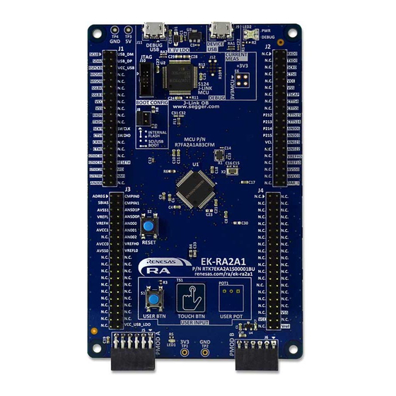
Renesas RA Microcontrollers EK-RA2A1 v1 – User's Manual 1. Kit Overview The EK-RA2A1 v1 enables developers to get started with initial firmware development. • Renesas RA2A1 Microcontroller Group R7FA2A1AB3CFM 64-pin LQFP package 48 MHz Arm ® ®... - Page 7 Renesas RA Microcontrollers EK-RA2A1 v1 – User's Manual Figure 1. EK-RA2A1 v1 Top Side R20UT4580EU0100 Rev.1.00 Page 4 of 29 Oct.02.19...
- Page 8 Renesas RA Microcontrollers EK-RA2A1 v1 – User's Manual Figure 2. EK-RA2A1 v1 Bottom Side R20UT4580EU0100 Rev.1.00 Page 5 of 29 Oct.02.19...
-
Page 9: Assumptions And Advisory Notes
Renesas RA Microcontrollers EK-RA2A1 v1 – User's Manual 1.1 Assumptions and Advisory Notes 1. It is assumed that the user has a basic understanding of microcontrollers and embedded systems hardware 2. It is recommended that the user refers to the EK-RA2A1 - Quick Start Guide to become acquainted with the kit and the Quick Start example the EK-RA2A1 comes preprogrammed with. -
Page 10: Hardware Details
Renesas RA Microcontrollers EK-RA2A1 v1 – User's Manual 4. Hardware Details 4.1 Jumpers Settings 4.1.1 Copper Jumpers Copper jumpers are of two types, designated trace-cut and solder-bridge. A trace-cut jumper is provided with a narrow copper trace connecting its pads. The silk screen overlay printing around a trace-cut jumper is a solid box. - Page 11 Renesas RA Microcontrollers EK-RA2A1 v1 – User's Manual Location Circuit Group Default Function Open/Closed Capacitive Touch Closed Enable/Disable Capacitive Touch Button Button (connects P001 on MCU to Capacitive Touch Button) Open Connects P001 on MCU to J2-20 EXT VCL and VCL CAP Open...
-
Page 12: Hardware Layout
Renesas RA Microcontrollers EK-RA2A1 v1 – User's Manual 5. Hardware Layout 5.1 System Block Diagram USB FS Host 12 M and J-Link Config USB FS 32 K 3.3V LDO S124 Jumpers Device Crystals Status Two-Color J-Link USB Renesas RA Family... -
Page 13: Power Supply Options
Renesas RA Microcontrollers EK-RA2A1 v1 – User's Manual 5.2.1 Power Supply Options EK-RA2A1 board can be powered in several different ways as described in this section. Figure 6. Power Supply Options 5.2.1.1 Option 1: Debug USB (default) The default power source is 5V, supplied from an external USB host to the USB Debug connector labelled DEBUG USB on the top surface of the board. -
Page 14: Option 4: Pin Headers
Renesas RA Microcontrollers EK-RA2A1 v1 – User's Manual 5.2.1.4 Option 4: Pin Headers EK-RA2A1 board can also be powered through the following pin-headers. • J1 (pin J1-15 for +3.3V, pin J1-17 for Return) • J2 (pin J2-10 for +3.3V, pin J2-12 for Return) •... -
Page 15: Measuring Current Consumption
Renesas RA Microcontrollers EK-RA2A1 v1 – User's Manual 5.2.3 Measuring Current Consumption Pads 1 and 3 of copper jumper E6, which is a trace-cut jumper, allow measurement of +3V3 MCU supply current. Trace is connected by default and should be cut to enable power measurement. Care must be taken when cutting the trace to not cause damage to PCB layers below the trace. -
Page 16: Major Components
Renesas RA Microcontrollers EK-RA2A1 v1 – User's Manual 5.3 Major Components • Main MCU RA2A1 MCU, part number R7FA2A1AB3CFM (U1) • Main MCU • J-Link MCU S124 MCU, part number R7FS124773A01CFM#AA0 (U2) • J-Link MCU • USB Connectors ... -
Page 17: Debug Usb
Renesas RA Microcontrollers EK-RA2A1 v1 – User's Manual Table 2. DEVICE USB connector (J9) USB device connector EK-RA2A1 Description Signal/Bus +5VUSB +5VDC, connected to a sense voltage 2/3 divider to allow Main MCU sensing of Host presence P407/USB_VBUS = 2/3(5VUSB) -
Page 18: Leds
Renesas RA Microcontrollers EK-RA2A1 v1 – User's Manual JTAG Connector EK-RA2A1 SWD pin name Signal/Bus SWCLK U1 P300/SWCLK (U1-32) N.C. N.C. N.C. N.C. N.C. N.C. GNDDetect N.C. (short E31 to connect to GND) nSRST U1 RESET# (U1-25) ® ® The Cortex Debug Connector is fully described in the Arm CoreSight™... -
Page 19: Switches
Renesas RA Microcontrollers EK-RA2A1 v1 – User's Manual 5.4.5 Switches Two miniatures, momentary, mechanical push-button type SMT switches are mounted on the PCB. Pressing the RESET Switch generates a reset signal to restart the Main MCU. To disconnect the User Switch from the MCU signal P206/IRQ6_A, copper jumper E4 must be open. -
Page 20: Pmod A
Renesas RA Microcontrollers EK-RA2A1 v1 – User's Manual Figure 19. Reset Switch (S2) on Board 5.4.6 PMOD A A 12-pin PMOD type 2A connector is provided at PMOD A. The interface is powered for 3.3V modules only. The Main MCU acts as the SPI master, and the connected module acts as an SPI slave device. -
Page 21: User Capacitive Touch Button
Renesas RA Microcontrollers EK-RA2A1 v1 – User's Manual Limits of the 3.3V regulator , and limits of the power source supplying that regulator (especially for USB Host devices), including the to-be-connected PMOD device, must be considered prior to connecting a module to a PMOD connector. -
Page 22: Pin Headers
Primary Fixed Function Pins share the same functionality across EK-RA6M1, EK-RA6M2, EK-RA4M1, and EK-RA2A1 boards. Secondary Fixed Function Pins share common pin assignments with other Renesas RA Family Evaluation Kits that have Main MCUs with the same functionality. The Secondary Fixed Function Pins are also labeled with the top side having a functional label, and bottom side having a port label. -
Page 23: Pin Header J1
Renesas RA Microcontrollers EK-RA2A1 v1 – User's Manual 5.5.1 Pin Header J1 Pin Header J1 is a 2-column by 20-row through-hole header on 2.54 mm centers. Table 10. Pin Header J1 Pin Assignment 64p Pin Port/Signal J1 Pins Port/Signal 64p Pin... -
Page 24: Pin Header J3
Renesas RA Microcontrollers EK-RA2A1 v1 – User's Manual 64p Pin Port/Signal J2 Pins Port/Signal 64p Pin P213/XTAL P111/TS14 P214/XCOUT P003/AN006 P215/XCIN P015/AN003 P107/AN023 VBAT P106/AN022 (None) VREFH0 (None) VREFL0 (None) AVSS0 (None) AVCC0 (None) P002/DA8_1 Color Key Primary Fixed Function pins Secondary Fixed Function pins 5.5.3 Pin Header J3... -
Page 25: Pin Header J4
Renesas RA Microcontrollers EK-RA2A1 v1 – User's Manual 5.5.4 Pin Header J4 Pin Header J4 is a 2-column by 20-row through-hole header on 2.54 mm centers. Table 13. Pin Header J4 Pin Assignment 64p Pin Port/Signal J4 Pins Port/Signal 64p Pin... -
Page 26: User Potentiometer
Renesas RA Microcontrollers EK-RA2A1 v1 – User's Manual The MCU pins for the 32.768 kHz clock crystal may be connected to P214 and P215. To disconnect the 32.768 kHz crystal, open copper jumpers E25 and E26, and close copper jumpers E22 and E27. -
Page 27: Boot Configuration
Renesas RA Microcontrollers EK-RA2A1 v1 – User's Manual 5.6.4 Boot Configuration The BOOT CONFIG jumper, J8, is used to configure the operating mode of the RA2A1 MCU at boot. Table 15. Boot Configuration Boot Configuration J8 Shunt Location Normal Boot (default) -
Page 28: Vcl
Renesas RA Microcontrollers EK-RA2A1 v1 – User's Manual 5.6.5.2 VCL By default, the Main MCU pin VCL is connected to reference capacitor C17. To connect this pin to MCU pin header J2, solder bridge E28 must be closed. To disconnect the reference capacitor C17, copper jumper E29 must be open. -
Page 29: Signal P408/Cmpin1/Can
Renesas RA Microcontrollers EK-RA2A1 v1 – User's Manual 5.6.5.6 Signal P408/CMPIN1/CAN By default, the Main MCU pin P408 is connected to both CAN and CMPIN1. P408/CAN is connected to J1, and P408/CMPIN1 is connected to J3. To disconnect P408/CAN from J1, copper jumper E41 must be open. -
Page 30: Certifications
Renesas RA Microcontrollers EK-RA2A1 v1 – User's Manual 6. Certifications The EK-RA2A1 v1 meets the following certifications/standards. See page 3 of this User’s Manual for the disclaimer and precautions. 6.1 EMC/EMI Standards • FCC Notice (Class A) This device complies with part 15 of the FCC Rules. Operation is subject to the following two conditions: (1) This device may not cause harmful interference, and (2) this device must accept any interference received, including interference that may cause undesired operation. -
Page 31: Design And Manufacturing Information
EK-RA2A1 v1 – User's Manual 7. Design and Manufacturing Information The design and manufacturing information about EK-RA2A1 v1 board are available in the “EK-RA2A1v1 Design Package” available on renesas.com/ra/ek-ra2a1. • Design package file name: ek-ra2a1-v1-designpackage.zip • Design package contents File Type... -
Page 32: Revision History
Renesas RA Microcontrollers EK-RA2A1 v1 – User's Manual Revision History Description Rev. Date Page Summary 1.00 Oct.02.19 Initial release R20UT4580EU0100 Rev.1.00 Page 29 of 29 Oct.02.19... - Page 33 EK-RA2A1 v1 Publication Date: Oct.02.19 Published by: Renesas Electronics Corporation...
- Page 34 EK-RA2A1 v1 – User's Manual R20UT4580EU0100...
Need help?
Do you have a question about the RA2A1 Series and is the answer not in the manual?
Questions and answers