Table of Contents
Advertisement
Quick Links
RA4M3 Group
Evaluation Kit for RA4M3 Microcontroller Group
Renesas RA Family
RA4 Series
All information contained in these materials, including products and product specifications, represents
information on the product at the time of publication and is subject to change by Renesas Electronics
Corp. without notice. Please review the latest information published by Renesas Electronics Corp.
through various means, including the Renesas Electronics Corp. website (http://www.renesas.com).
www.renesas.com
EK-RA4M3 v1
User's Manual
Rev. 1.00 Nov 2020
Advertisement
Table of Contents

Related Manuals for Renesas RA4M3


Summary of Contents for Renesas RA4M3
- Page 1 All information contained in these materials, including products and product specifications, represents information on the product at the time of publication and is subject to change by Renesas Electronics Corp. without notice. Please review the latest information published by Renesas Electronics Corp.
- Page 2 Renesas Electronics disclaims any and all liability for any damages or losses incurred by you or any third parties arising from the use of any Renesas Electronics product that is inconsistent with any Renesas Electronics data sheet, user’s manual or other Renesas Electronics document.
- Page 3 Unit Products The following usage notes are applicable to all Microprocessing unit and Microcontroller unit products from Renesas. For detailed usage notes on the products covered by this document, refer to the relevant sections of the document as well as any technical updates that have been issued for the products.
- Page 4 Renesas or its affiliates shall in no event be liable for any loss of profit, loss of data, loss of contract, loss of business, damage to reputation or goodwill, any economic loss, any reprogramming or recall costs (whether the foregoing losses are direct or indirect) nor shall Renesas or its affiliates be liable for any other direct or indirect special, incidental or consequential damages arising out of or in relation to the use of this EK-RA4M3, even if Renesas or its affiliates have been advised of the possibility of such damages.
-
Page 5: Table Of Contents
User’s Manual Renesas RA Family EK-RA4M3 v1 Contents Kit Overview ..........................4 Assumptions and Advisory Notes ......................6 Kit Contents ..........................7 Kit Ordering Information ......................7 Hardware Architecture and Default Configuration ..............8 Kit Architecture ............................8 System Block Diagram ..........................9 Jumper Settings ............................. - Page 6 Figure 1. EK-RA4M3 Board Top Side ......................5 Figure 2. EK-RA4M3 Board Bottom Side ......................6 Figure 3. EK-RA4M3 Kit Contents ........................7 Figure 4. EK-RA4M3 Board Functional Area Definitions ................. 8 Figure 5. EK-RA4M3 Board Block Diagram ....................9 Figure 6. Copper Jumpers ..........................10 Figure 7.
- Page 7 Table 18. EK-RA4M3 Board LED Functions ....................23 Table 19. EK-RA4M3 Board Switches ....................... 23 Table 20. Quad-SPI Flash Port Assignments .................... 24 Table 21. EK-RA4M3 Board Design Package Contents ................28 R20UT4803EG0100 Rev 1.00 Page 3 of 29 Nov.09.20...
-
Page 8: Kit Overview
IDE. The users can utilize rich on-board features along with their choice of popular ecosystems add-ons to bring their big ideas to life. The key features of the EK-RA4M3 board are categorized in three groups (consistent with the architecture of the kit) as follows: MCU Native Pin Access •... -
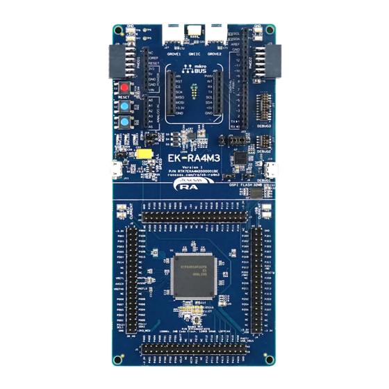
Page 9: Figure 1. Ek-Ra4M3 Board Top Side
Renesas RA Family EK-RA4M3 v1 – User's Manual Figure 1. EK-RA4M3 Board Top Side R20UT4803EG0100 Rev 1.00 Page 5 of 29 Nov.09.20... -
Page 10: Assumptions And Advisory Notes
1. It is assumed that the user has basic understanding of microcontrollers and embedded systems hardware. 2. It is recommended that the user refers to the EK-RA4M3 Quick Start Guide to get acquainted with the kit and the Quick Start example project that EK-RA4M3 board comes pre-programmed with. -
Page 11: Kit Contents
3. Kit Ordering Information • EK-RA4M3 v1 kit orderable part number: RTK7EKA4M3S00001BE Note: The underlined character in the orderable part number represents the kit version. • EK-RA4M3 board dimensions: 80 mm (width) x 165mm (length) R20UT4803EG0100 Rev 1.00 Page 7 of 29 Nov.09.20... -
Page 12: Hardware Architecture And Default Configuration
4. Hardware Architecture and Default Configuration 4.1 Kit Architecture The EK-RA4M3 board is designed with three sections or areas to help shorten the learning curve of the users and maximize the design and knowledge reuse among similar kits. The contents of these three areas are conceptually standardized among similar kits. -
Page 13: System Block Diagram
Device Switch System Control & and Host Ecosystem Access Special Feature Access 32 MB Quad-SPI Quad-SPI Flash Native Pin Access Voltage/ Power Current Meas. Probes Jumper Figure 5. EK-RA4M3 Board Block Diagram R20UT4803EG0100 Rev 1.00 Page 9 of 29 Nov.09.20... -
Page 14: Jumper Settings
4.3.2 Traditional Pin Header Jumpers These jumpers are traditional small pitch jumpers that require an external shunt to open/close them. The traditional pin jumpers on the EK-RA4M3 board are 2 mm pitch headers and require compatible 2 mm shunt jumpers. - Page 15 Renesas RA Family EK-RA4M3 v1 – User's Manual Location Circuit Group Default Open/Closed Function Jumper on pins 3-4 Jumper on pins 5-6 Jumper on pins 7-8 MCU Boot Mode Open Configures the MCU for normal boot mode USB FS Jumper on pins 2-3...
-
Page 16: System Control And Ecosystem Access Area
EK-RA4M3 v1 – User's Manual 5. System Control and Ecosystem Access Area The following figure shows the System Control and Ecosystem Access area on the EK-RA4M3 board. Subsequent sections detail the features and functionality provided in the area. Figure 7. System Control and Ecosystem Access Area R20UT4803EG0100 Rev 1.00... -
Page 17: Power
5.1.3 Power-up Behavior When powered, the white LED near the center of the board (the “dash” in the EK-RA4M3 name) will light up. For more details on initial power up behavior, see the EK-RA4M3 Quick Start Guide. -
Page 18: Debug And Trace
J10-5 Ground A yellow indicator, LED5, shows the visual status of the debug interface. When the EK-RA4M3 board is powered on, and LED5 is blinking, it indicates that the S124 Debug MCU is not connected to a programming host. When LED5 is on solid, it indicates that the S124 Debug MCU is connected to a programming interface. -
Page 19: Debug In
Debug Connector at J13 supports JTAG and SWD. Either of these connectors may be used for external debug of the target RA MCU. To configure the EK-RA4M3 board to use the Debug in mode, configure the jumpers using the following table. -
Page 20: Debug Out
Architecture Specification. 5.2.3 Debug Out The EK-RA4M3 board can be configured to use the S124 Debug MCU to debug target RA MCU on an external board. A yellow indicator, LED5, shows the visual status of the debug interface. When the EK-RA4M3 board is powered on, and LED5 is blinking, this indicates that the S124 Debug MCU is not connected to a programming host. -
Page 21: Ecosystem
Renesas RA Family EK-RA4M3 v1 – User's Manual To configure the EK-RA4M3 board to use the Debug Out mode, configure the jumpers according to the following table. Table 9. Debug Out Jumper Configuration Location Default Open/Closed Function Open No connection to RA MCU... -
Page 22: Sparkfun Qwiic Connector
Renesas RA Family EK-RA4M3 v1 – User's Manual ® ® 5.3.2 SparkFun Qwiic Connector A Qwiic connector is provided at J30. The Main MCU acts as a two-wire serial master, and a connected module acts as a two-wire serial slave. (Data lines shared with Grove 1.) Table 12. -
Page 23: Figure 12. Pmod 1 Trace Cut Jumpers
Table 13. The trace cut jumpers are shown in Figure Note: Exercise caution while modifying power source trace jumpers, E16 and E17. Permanent damage to the EK-RA4M3 board and/or connected modules may result. Figure 12. Pmod 1 Trace Cut Jumpers 5.3.3.2 Pmod 2... -
Page 24: Arduino™ Connector
Renesas RA Family EK-RA4M3 v1 – User's Manual Figure 13. Pmod 2 5.3.4 Arduino™ Connector Near the center of the System Control and Ecosystem Access area is an Arduino Uno R3 compatible connector interface. Table 15. Arduino Uno Connections Arduino Compatible Connector... -
Page 25: Mikroelektronika™ Mikrobus Connector
Renesas RA Family EK-RA4M3 v1 – User's Manual Arduino Compatible Connector EK-RA4M3 Description Signal/Bus J24-9 I2C_SDA P511 (SDA1) J24-10 I2C_SCL P512 (SCL1) Figure 14. Arduino Uno Connectors 5.3.5 MikroElektronika™ mikroBUS Connector In the center of the System Control and Ecosystem Access area is a mikroBUS compatible connector interface. -
Page 26: Connectivity
U6. The total current available from U6 is 500 mA. Note that the input power sources must be configured with enough power for both the EK-RA4M3 board and the USB Full Speed port in host mode. Connect the included USB type-A female to micro-B male cable to J11. USB device cables or devices can be connected to the USB Full Speed port using this cable. -
Page 27: Miscellaneous
EK-RA4M3 v1 – User's Manual 5.5 Miscellaneous 5.5.1 User and Power LEDs 5 LEDs are provided on the EK-RA4M3 board. Behavior of the LEDs on the EK-RA4M3 board is described in the following table. Table 18. EK-RA4M3 Board LED Functions Designator Color... -
Page 28: Mcu Boot Mode
Chip mode, leave J16 open. To enter SCI Boot mode or USB Boot mode, place a jumper on J16. Figure 20. Boot Mode Note: The RA MCU fitted to the EK-RA4M3 board may not contain the latest version of the on-chip boot firmware. -
Page 29: Mcu Native Pin Access Area
Renesas RA Family EK-RA4M3 v1 – User's Manual Figure 22. Quad-SPI Flash 7. MCU Native Pin Access Area Figure 23. Native Pin Access Area R20UT4803EG0100 Rev 1.00 Page 25 of 29 Nov.09.20... -
Page 30: Breakout Pin Headers
7.1 Breakout Pin Headers The EK-RA4M3 board pin headers, J1, J2, J3 and J4, provide access to all RA MCU interface signals, and to voltages for all RA MCU power ports. Each header pin is labeled with the voltage or port connected to that pin. -
Page 31: Certifications
Renesas RA Family EK-RA4M3 v1 – User's Manual 8. Certifications The EK-RA4M3 v1 kit meets the following certifications/standards. See page 3 of this user’s manual for the disclaimer and precautions. 8.1 EMC/EMI Standards • FCC Notice (Class A) This device complies with part 15 of the FCC Rules. Operation is subject to the following two conditions: (1) This device may not cause harmful interference, and (2) this device must accept any interference received, including interference that may cause undesired operation. -
Page 32: Design And Manufacturing Information
Renesas RA Family EK-RA4M3 v1 – User's Manual 9. Design and Manufacturing Information The design and manufacturing information for the EK-RA4M3 v1 kit is available in the “EK-RA4M3v1 Design Package” available on renesas.com/ra/ek-RA4M3. • Design package file name: ek-RA4M3-v1-designpackage.zip •... -
Page 33: Revision History
Renesas RA Family EK-RA4M3 v1 – User's Manual Revision History Description Rev. Date Page Summary 1.00 Nov.09.20 — Initial release R20UT4803EG0100 Rev 1.00 Page 29 of 29 Nov.09.20... - Page 34 EK-RA4M3 v1 – User’s Manual Publication Date: Nov.09.20 Published by: Renesas Electronics Corporation...
- Page 35 EK-RA4M3 v1 – User’s Manual R20UT4803EG0100...
Need help?
Do you have a question about the RA4M3 and is the answer not in the manual?
Questions and answers