Renesas RA6M5 Quick Start Manual
Evaluation kit
Hide thumbs
Also See for RA6M5:
- User manual (40 pages) ,
- User manual (35 pages) ,
- User manual (33 pages)
Table of Contents
Advertisement
Quick Links
RA6M5 Group
Evaluation Kit for RA6M5 Microcontroller Group
Renesas
RA Family
RA6 Series
All information contained in these materials, including products and product specifications, represents
information on the product at the time of publication and is subject to change by Renesas Electronics
Corp. without notice. Please review the latest information published by Renesas Electronics Corp.
through various means, including the Renesas Electronics Corp. website (http://www.renesas.com).
www.renesas.com
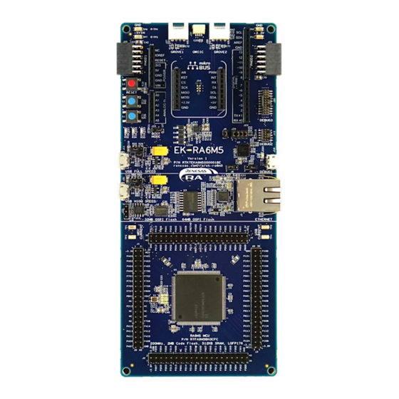
EK-RA6M5
Quick Start Guide
Rev. 1.01 Apr 2021
Advertisement
Table of Contents

Related Manuals for Renesas RA6M5


Summary of Contents for Renesas RA6M5
- Page 1 All information contained in these materials, including products and product specifications, represents information on the product at the time of publication and is subject to change by Renesas Electronics Corp. without notice. Please review the latest information published by Renesas Electronics Corp.
- Page 2 Renesas Electronics disclaims any and all liability for any damages or losses incurred by you or any third parties arising from the use of any Renesas Electronics product that is inconsistent with any Renesas Electronics data sheet, user’s manual or other Renesas Electronics document.
- Page 3 Unit Products The following usage notes are applicable to all Microprocessing unit and Microcontroller unit products from Renesas. For detailed usage notes on the products covered by this document, refer to the relevant sections of the document as well as any technical updates that have been issued for the products.
- Page 4 Terms and Conditions available at https://www.renesas.com/en-us/legal/disclaimer.html. The EK-RA6M5 is not guaranteed to be error free, and the entire risk as to the results and performance of the EK-RA6M5 is assumed by the User. The EK- RA6M5 is provided by Renesas on an “as is” basis without warranty of any kind whether express or implied, including but not limited to the implied warranties of good workmanship, fitness for a particular purpose, title, merchantability, and non-infringement of intellectual property rights.
-
Page 5: Table Of Contents
Figure 1. EK-RA6M5 Kit Contents ........................7 Figure 2. Quick Start Example Project Flow ....................8 Figure 3. Connecting the EK-RA6M5 Board to the Host PC via USB Full Speed Port ........9 Figure 4. USB Serial Device in Windows Device Manager ................10 Figure 5. - Page 6 Figure 34. Successful Build Output ....................... 27 Figure 35. DHCP Setting in FreeRTOS + TCP Stack ................... 28 Figure 36. Connecting the EK-RA6M5 Board to the Host PC via USB Debug Port ........29 Figure 37. Selecting the Debug Option ......................30 Figure 38.
-
Page 7: Ek-Ra6M5
3. Prior to running the Quick Start example project or programming the EK-RA6M5 board, default jumper settings must be used. Refer to the EK-RA6M5 user’s manual for the default jumper settings. 4. The screen shots provided throughout this document are for reference. The actual screen content may differ depending on the version of software and development tools used. -
Page 8: Overview Of The Quick Start Example Project
10%, 50%, and 90%. When the EK-RA6M5 board running the Quick Start example project is connected to a host PC via USB as a Full Speed CDC Device, the kit information, MCU die temperature, and user LED blinking frequency are displayed on a terminal console. -
Page 9: Running The Quick Start Example Project
RA6M5 board lights up white, indicating that the EK-RA6M5 board is powered on. Note: If the EK-RA6M5 board is not powered through micro-AB USB Full Speed port (J11) and the host PC, then USB CDC functionality of the Quick Start example project cannot be fully demonstrated because of the absence of a USB Full Speed Device connection with the host PC. -
Page 10: Running The Quick Start Example Project
Note: The debug LED (LED5) will blink or light up orange; this can be ignored for now. 2. Press the user button (S1) on the EK-RA6M5 board to change the intensity of the user LED1. With every press of the user button (S1), the intensity will switch from 10% to 50% to 90% and cycle back. -
Page 11: Figure 5. Selecting The Serial Port On Tera Term
Renesas RA Family EK-RA6M5 – Quick Start Guide 5. Open Tera Term, select Serial and COMxx: USB Serial Device (COMxx) and click OK. Figure 5. Selecting the Serial Port on Tera Term 6. Using the Setup menu pull-down, select Serial port… and ensure that the speed is set to 115200, as shown below. -
Page 12: Figure 7. Welcome And Main Menu
9. Press space to return to the ‘welcome and main menu’ screen. 10. Press 2 to display the Web Server. This application hosts a web server on the EK-RA6M5 kit showing communication with the host PC as a remote client. -
Page 13: Figure 10. Using Dhcp
Renesas RA Family EK-RA6M5 – Quick Start Guide 11. Connect the Ethernet cable and press tab. The EK-RA6M5 as supplied, is configured to use DHCP for IP address resolution. Upon successful connection the following is displayed. Figure 10. Using DHCP If the DHCP fails to resolve a route or the DHCP server has been disabled, the application uses the static IP defined in the project. -
Page 14: Figure 12. Browser View
12. Once a successful network connection is established, open the web browser on the host PC. Type the IP address of the EK-RA6M5 kit as shown in the Tera Term window in the address bar of the web browser. The following should be displayed in the web browser. -
Page 15: Figure 13. Network Name Lookup
Renesas RA Family EK-RA6M5 – Quick Start Guide 13. In Tera Term, press space to return to the ‘welcome and main menu’ screen. 14. Press 3 to display the Network Name Lookup. This application performs a DNS look up of renesas.com... -
Page 16: Figure 15. Using Static Ip
Renesas RA Family EK-RA6M5 – Quick Start Guide If the DHCP fails to resolve a route or the DHCP server has been disabled, the application uses the static IP defined in the project. The following should be displayed. Figure 15. Using Static IP Note: If desired, the user may configure DHCP/static IP and MAC address using the project configuration (see section 5.4). -
Page 17: Figure 16. External Memory Read Write
Renesas RA Family EK-RA6M5 – Quick Start Guide 17. Press space to return to the ‘welcome and main menu’ screen. 18. Press 4 to display Octo-SPI and Quad-SPI Speed Comparison. This application demonstrates the read and write performance between the external Octo-SPI and Quad-SPI flash memories. -
Page 18: Figure 18. Cryptography Using Usb High Speed Fat32
Renesas RA Family EK-RA6M5 – Quick Start Guide 22. Press 5 to display Cryptography using USB High speed FAT32. Figure 18. Cryptography using USB High speed FAT32 23. Optional press space to abort the demonstration. NOTE you cannot abort once tab has been pressed. -
Page 19: Figure 20. Cryptography Successful
Renesas RA Family EK-RA6M5 – Quick Start Guide 24. Optional connect a FAT32 formatted USB Memory stick and press tab key to start. USB Memory stick must contain a text file under 1KB in size called “source.txt”. File must be at least 1 byte to encrypt. -
Page 20: Customizing The Quick Start Example Project
1. Download and extract the Quick Start example project to a local directory on the host PC. The Quick Start example project (source code and project files) is available in the EK-RA6M5 Example Projects Bundle that is available in the Downloads tab of EK-RA6M5 webpage at renesas.com/ra/ek-ra6m5... -
Page 21: Figure 23. Launching The Workspace
Renesas RA Family EK-RA6M5 – Quick Start Guide 4. Click Launch. Figure 23. Launching the Workspace 5. Click Import from the File drop-down menu. Figure 24. Importing the Project R20QS0021EG0101 Rev.1.01 Page 21 of 33 Apr.15.21... -
Page 22: Figure 25. Importing Existing Projects Into The Workspace
Renesas RA Family EK-RA6M5 – Quick Start Guide 6. In the Import dialog box, select General, and then select Existing Projects into Workspace. Figure 25. Importing Existing Projects into the Workspace 7. Click Next. Figure 26. Clicking Next to Import Existing Projects into the Workspace R20QS0021EG0101 Rev.1.01... -
Page 23: Figure 27. Selecting The Root Directory
Renesas RA Family EK-RA6M5 – Quick Start Guide 8. Click Select root directory and click Browse to go to the location of the Quick Start example project folder. Figure 27. Selecting the Root Directory R20QS0021EG0101 Rev.1.01 Page 23 of 33... -
Page 24: Figure 28. Finishing Importing The Quick Start Example Project
Renesas RA Family EK-RA6M5 – Quick Start Guide 9. Select the Quick Start example project and click Finish. Figure 28. Finishing Importing the Quick Start Example Project R20QS0021EG0101 Rev.1.01 Page 24 of 33 Apr.15.21... -
Page 25: Modifying, Generating, And Building The Quick Start Example Project
Renesas RA Family EK-RA6M5 – Quick Start Guide 5.3 Modifying, Generating, and Building the Quick Start Example Project This section provides instructions to modify the Quick Start example project. The Quick Start example project can be modified by editing the source code and reconfiguring the properties of the MCU peripherals, pins, clocks, interrupts, and so forth. -
Page 26: Figure 31. Modifying The Configuration Settings
Renesas RA Family EK-RA6M5 – Quick Start Guide Figure 31. Modifying the Configuration Settings R20QS0021EG0101 Rev.1.01 Page 26 of 33 Apr.15.21... -
Page 27: Figure 32. Saving The Configuration Changes
Renesas RA Family EK-RA6M5 – Quick Start Guide 3. After the desired modifications are made, click Generate Project. A dialog box may appear with an option of saving the configuration changes. Click Proceed. Figure 32. Saving the Configuration Changes 4. Modify the source files in the /src folder as needed and save the changes. -
Page 28: Dhcp And Static Ip Settings
Renesas RA Family EK-RA6M5 – Quick Start Guide 5.4 DHCP and Static IP settings To modify the Ethernet based sample to enable/disable DHCP use the FreeRTOS+TCP setting in the stack. The FSP Configuration view must be active to access the stack items properties. -
Page 29: Setting Up Debug Connection Between The Ek-Ra6M5 Board And Host Pc
Note: The debug LED (LED5) continues to blink when J-Link drivers are not detected by the EK-RA6M5 board. In that case, make sure that the EK-RA6M5 board is connected to the host PC through the micro-B USB debug port (J10) and that J-Link drivers are installed on the host PC by checking in the Windows Device Manager (expand Universal Serial Bus controller, and locate J-Link driver). -
Page 30: Downloading And Running The Modified Quick Start Example Project
Debug Configurations option. Figure 37. Selecting the Debug Option 2. In the dialogue, on the left-hand pane, expand the Renesas GDB Hardware Debugger and select the built image to debug. In this case, the quickstart_ek_ra6m5_ep Debug_Flat. -
Page 31: Firewall Dialogue
4. Press F8 or click Resume icon to begin executing the project. Figure 40. Executing the Project 5. The modified Quick Start example project is programmed into the EK-RA6M5 board and is running. The project can be paused, stopped, or resumed using the debug controls. -
Page 32: Next Steps
Renesas RA Family EK-RA6M5 – Quick Start Guide 6. Next Steps 1. To learn more about the EK-RA6M5 kit, refer to the EK-RA6M5 user’s manual and design package available in the Documents and Download tabs respectively of the EK-RA6M5 webpage at renesas.com/ra/ek-ra6m5 2. -
Page 33: Revision History
Renesas RA Family EK-RA6M5 – Quick Start Guide Revision History Description Rev. Date Page Summary 1.00 Mar.12.21 — Initial release 1.01 Apr.15.21 Update Static IP configuration in section 5.4 R20QS0021EG0101 Rev.1.01 Page 33 of 33 Apr.15.21... - Page 34 EK-RA6M5 – Quick Start Guide Publication Date: Apr.15.21 Published by: Renesas Electronics Corporation...
- Page 35 EK-RA6M5 – Quick Start Guide R20QS0021EG0101...
Need help?
Do you have a question about the RA6M5 and is the answer not in the manual?
Questions and answers