
Related Manuals for Target fairfax TGCRCNTB01


Summary of Contents for Target fairfax TGCRCNTB01
- Page 1 # TGCRCNTB01 dpci # 249-17-4092 TCIN # 54571166 >> assembly instructions © 2019 Target. The Bullseye Design is a trademark of Target Brands, Inc. All rights reserved.
- Page 2 Congratulations on your latest Target purchase. Now what? Don’t start sweating over this box of parts. This will be easy. We did the hard work for you. All you need to do is follow our simple instructions and you’ll be on your way to transforming your room in no time.
- Page 3 table of contents introduction hardware parts list how to use the cam lock system assembly 7-14 QUESTIONS? Just call 1-855-MYTGTHOME (855-698-4846) for parts and service. For faster service, have the style number and dpci number ready when calling.
- Page 4 hardware (H1) x 20 (H2) x 11 (H3) x 11 (H4) x 4 (H5) x 1 wooden dowel cam bolt bolt allen wrench (H6) x 6 (H7) x 7 (H8) x 1 (H9) x 1 (H10) x 1 pan head screw cam cover small pan head screw wall strap...
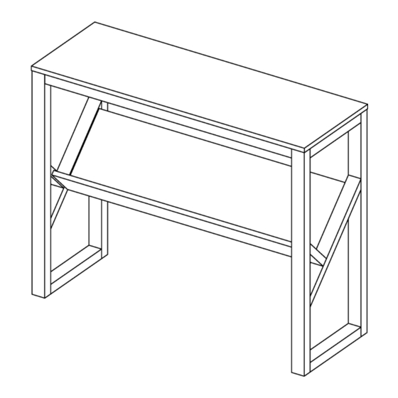
- Page 5 exploded diagram ITEM DESCRIPTION QUANTITY top panel left side frame right side frame upper rail front panel rear panel...
- Page 6 how to use the cam lock system Screw cam bolt into panel Align cam bolt(s) with cam(s) Push cam into panel - arrow feature and insert all the way into on cam top points to panel edge cross-bored hole(s) Rotate cam(s) clockwise 180° to Panels should be tight against each lock panels together other and connection should be rigid...
- Page 7 step 1: attach upper rails to left side frame (H1) x 2 (H2) x 4 (H3) x 2 wooden dowel cam bolt 1.1. Carefully tap small wooden dowels into place in left side frame. Leave 1/2” of the dowels sticking out. Carefully tap small wooden dowels into place in left side frame.
- Page 8 step 2: attach rear panel to front panel (H1) x 2 (H2) x 3 (H3) x 3 wooden dowel cam bolt 2.1. Carefully tap small wooden dowels into place in front panel. Leave 1/2” of the dowels sticking out. 2.2. Screw-In cam bolts must be screwed down flush in front panel. 2.3.
- Page 9 step 3: attach front/rear panels to left side frame (H1) x 3 (H3) x 2 wooden dowel 3.1. Carefully tap small wooden dowels into place in left side frame. Leave 1/2” of the dowels sticking out. 3.2. Refer to page 6 for instructions on how to use the cam lock system.
- Page 10 step 4: attach right side frame (H1) x 5 (H2) x 4 (H3) x 4 (H3) x 4 wooden dowel cam bolt 4.1. Carefully tap small wooden dowels into place in right side frame. Leave 1/2” of the dowels sticking out. Carefully tap small wooden dowels into place in right side frame.
- Page 11 step 5: align top panel with side frames / upper rails (H1) x 8 wooden dowel 5.1. Carefully tap small wooden dowels into place side panels and upper rails. Leave 1/2” of the dowels sticking out.
- Page 12 step 6: attach top panel (H4) x 4 (H5) x 1 (H6) x 6 bolt allen wrench pan head bolt 6.1. Align bolts with pre-drilled holes in side frames. 6.2. Align screws with pre-drilled holes in upper rails. 6.3. Do not over tighten screws.
- Page 13 step 7: attach cam covers (H7) x 7 cam cover 7.1. Attach cam covers to visible cams.
- Page 14 step 8: install anti-tip hardware (H10) Position against wall (H9) Mark position of strap hole on wall Mark position of strap hole on wall (H12) (H8) Drill 1/4” hole Tap in wall anchor (H12) adjustable leg levelers (H11) Fasten anti-tip strap with wall screw Fasten anti-tip strap with wall screw provided provided...
- Page 15 1. This unit has been designed for the weight shown. Exceeding this recommended weight could result in excessive “sagging” of the top. Extreme overloading can cause failure of the top and possible injury. 2. Furniture Care Instructions: Dust with a clean, lint-free cloth. Use a spray furniture polish as needed. QUESTIONS? Just call 1-855-MYTGTHOME (855-698-4846) for parts and service.
- Page 16 © 2019 Target. The Bullseye Design is a trademark of Target Brands, Inc. All rights reserved.
Need help?
Do you have a question about the fairfax TGCRCNTB01 and is the answer not in the manual?
Questions and answers