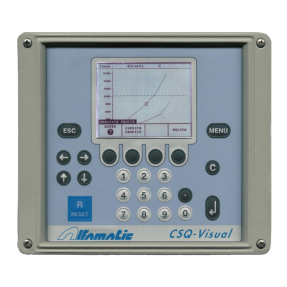
ALFAMATIC CSQ-Visual Installation Manual
Version with csqvio7 card
Hide thumbs
Also See for CSQ-Visual:
- User manual (46 pages) ,
- Installation manual (16 pages) ,
- Installation manual (16 pages)
Table of Contents
Advertisement
Quick Links
Advertisement
Table of Contents

Subscribe to Our Youtube Channel
Summary of Contents for ALFAMATIC CSQ-Visual
- Page 1 CSQ-Visual Version with CSQVIO7 card Installation manual Feb. 6, 2012...
-
Page 2: Table Of Contents
Operating of the instrument ......................3 Internal cards............................ 4 Electric wiring........................... 4 Configure automatic work selection ..................... 10 Configuring the use of the phases....................11 Connection of an external reset ..................... 12 SETPOINT output.......................... 12 Instructions for setting up the CSQ-Visual................... 12... -
Page 3: Installing Csq-Visual
This paragraph describes the operations necessary to fit and connect the CSQ-Visual to the machine and make it operative. The CSQ-Visual has been designed to be independent: all you have to do is connect the valves and sensors that will be powered by the instrument. Naturally there’s nothing to stop you from combined use with a PLC. -
Page 4: Internal Cards
1.4.1 Information for connection to an external controller (PLC) To connect the CSQ-Visual to a PLC, the latter must have PNP positive logic. The inputs and outputs of the instrument are optoinsulated from the instrument’s control electronics. The power supply of the instrument’s inputs and outputs must be the same that powers the inputs and outputs of the PLC. - Page 5 X5. The numbers are also printed on the printed circuit of the card. Figure 1 Main power terminal block (X24) The electronics of the CSQ-Visual and the transducers are powered at 24VDC via the X24 three- pole terminal block. Name Function...
- Page 6 Inputs terminal block (X3) The inputs are optoinsulated and compatible with clean contact signals or 24 VDC PNP transistor outputs. Name Function Terminal Description Input 0 START X3.1 Request for new cycle start X3.2 Do not use Input 1 T.D.C. X3.3 “Top dead point”...
- Page 7 Electrical features of terminals X5.5, X5.6 and X5.7 Electrical features of terminal X5.8 Load cell terminal block (X6) Input for load cell with resistive jumper with a sensitivity of 2mV/V. The power for supply the load cell is also available on this terminal block. Name Terminal Description...
- Page 8 Tipical connection...
- Page 9 The CSQVIO6 can mount a connector with an RS232 serial port and an RS485 serial port. The CSQ-Visual recognises and automatically selects the port connected. It is not possible to use both serial ports at the same time. The RS232 serial port can be used for connections with the computer (WinScope), for connection with a PLC or for connection with a barcode reader.
-
Page 10: Configure Automatic Work Selection
5V power supply or transducers with a 0-10mA output. 1.5 Configure automatic work selection The CSQ-Visual supports the automatic selection of work using the combination of the inputs or a command sent to the serial port. This selection can be useful for automatically recognising the piece or the tool fitted. -
Page 11: Configuring The Use Of The Phases
The CSQ-Visual is able to manage up to four phases for each single process. The choice of the phase may take place automatically, in succession or through the digital inputs of the instrument. -
Page 12: Connection Of An External Reset
Instructions for setting up the CSQ-Visual Always disconnect the instrument from the electricity supply before opening it. Open the CSQ-Visual by loosening the four screws in the corners of the front panel. Figure 3 Pull out the internal cards by a few centimetres. Then release the cards from the front panel. - Page 13 Figure 4 Pull out all the cards from the container and remove the five terminal block units. To fasten the instrument in place it is possible to perforate the container on the top or bottom (after removing all the cards) in the middle. Fit the wire passage and plugs.
- Page 14 Lastly, insert the terminal block units, paying attention to the direction. Make sure that cables are not squashed on the bottom of the instrument. After completing the wiring it is possible to supply power to the instrument, switching it on using the switch on the back and proceeding as follows: •...


Need help?
Do you have a question about the CSQ-Visual and is the answer not in the manual?
Questions and answers