Table of Contents
Advertisement
Quick Links
Advertisement
Table of Contents

Related Manuals for EWIKON pro CONTROL BASIC


Summary of Contents for EWIKON pro CONTROL BASIC
- Page 1 Hot runner controllers Operating manual...
-
Page 2: Table Of Contents
Symbols used: Notations Safety instructions ....................5 Intended use Information for operators and users Structure and functionality ................... 6 General information Structure 3.2.1 Pro CONTROL BASIC 2, 6 and 12 3.2.2 Operating front 3.2.3 LED-strip 3.2.4 Power card 3.2.5 Fuses 3.2.6... - Page 3 CONTROL BASIC Operating manual Functions and parameterization ................26 Basic settings 7.1.1 Access authorizations 7.1.2 Fahrenheit display 7.1.3 7.1.3 Thermocouple type Control behavior 7.2.1 Control parameters P I D 7.2.2 Output level 7.2.3 Maximal output level Heating 7.3.1 Softstart (Gentle heating) 7.3.2...
-
Page 4: List Of Figures
CONTROL BASIC Operating manual List of Figures Figure 1 – pro CONTROL BASIC front panel Figure 2 – Type label Figure 3 – Wiring of plug systems Figure 4 – Operating and display elements Figure 5 – Zone display Figure 5 –... -
Page 5: Introduction
CONTROL BASIC Operating manual Introduction Symbols used: Caution/Warning Information on possible damage to property or personal injury Information Important information Notations Menu structures between words are indicated by the > symbol and depicted in the same way on the device. -
Page 6: Structure And Functionality
Structure and functionality General information The pro CONTROL BASIC hot runner controllers are especially suited to the temperature con- trol of hot runner molds on injection molding machines. In use, the controllers are connected directly to the mold via cables. -
Page 7: Pro Control Basic 2, 6 And
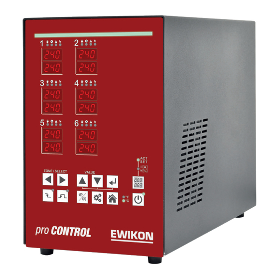
Figure 1 – pro CONTROL BASIC front panel 3.2.2 Operating front The convenient operation of the pro CONTROL BASIC hot runner controller is carried out on the front panel (Figure 1) via 12 keys. The front also contains all visualization elements. The setpoints and actual values of the individual zones are displayed via 7-segment displays. -
Page 8: Power Card
3.2.6 Notification contact / Digital input The pro CONTROL BASIC hot runner controllers have a potential-free message contact and a digital control input, which are brought out via a 7-pin plug on the rear of the unit. A contact diagram of the built-in plug is given in chapter 11.2. -
Page 9: Wiring Of The Plug Systems
CONTROL BASIC Operating manual 3.2.8 Wiring of the plug systems The plugs for connecting the temperature sensors and heating elements to a hot runner are available on the rear of the controller. The customer-specific wiring plan for the plug systems is located on the side of the controller housing (see Figure 3 for an example). -
Page 10: Commissioning
CONTROL BASIC Operating manual Commissioning Electrical connection Important! Before the device is connected to the supply voltage, a check must first be performed to ensure that the mains electricity conditions comply with the spec- ifications on the type plate. -
Page 11: Operating And Display Elements
CONTROL BASIC Operating manual Operating and display elements The operation as well as all display elements of the hot runner controllers is carried out via the soft keys on the front of the housing. The following illustration shows the front view of a 6- zone controller, from which all operating and display elements are shown. -
Page 12: Display Elements
CONTROL BASIC Operating manual 4.2.1 Display elements 4.2.1.1 Status display The status of the controller is indicated by a LED strip in the front. In control mode, this indicator lights up green. In case of a warning or alarm, the display changes to yellow or red (traffic light status). -
Page 13: Operating Elements Main Switch
CONTROL BASIC Operating manual 4.2.2 Operating elements 4.2.2.1 Main switch The main switch is located on the back of the hous- ing. The switch must be operated to switch the controller on and off. 4.2.2.2 Soft keys Operating element... - Page 14 CONTROL BASIC Operating manual Shift key for the zone display Display: actual value (ACT) and setpoint (SET) Display: Current (I[A]) and output level (Y[%]) Activating / deactivating the controller outputs Temperature unit of the display Page 14...
-
Page 15: Operation
CONTROL BASIC Operating manual Operation Zone selection 5.1.1 Selecting a zone Step Operation Description Each time the arrow keys are pressed, the display jumps one zone further. All other zones that are not selected are hidden. 5.1.2 Selecting multiple zones... -
Page 16: Selection Of All Zones
CONTROL BASIC Operating manual 5.1.4 Selection of all zones Step Operation Description The basic rule is: In the basic view, all zones can be operated and are virtu- ally already selected for a value change. "The Zones that you see can also be operated."... -
Page 17: Setpoints
CONTROL BASIC Operating manual Setpoints Step Operation Description Select the zone(s) as described in 5.1 Use the buttons to set the setpoint to the desired value. The display flashes, indicating that the value has not yet been accepted. Confirm the entry... -
Page 18: Output Rate
CONTROL BASIC Operating manual Output rate Step Operation Description Select the zone(s) as described in 5.1 Selection of the operating mode. Operate until manual mode is displayed. Confirm selection Switching the zone display to Current (I) and output rate (Y) Use the buttons to set the output level to the desired value. -
Page 19: Parameter
CONTROL BASIC Operating manual Parameter 5.6.1 Zone parameter Step Operation Description Select the zone(s) as described in 5.1 Press key to change to the parameterization level Select parameter. Each time the arrow keys are pressed, the parameter is incremented or decremented. -
Page 20: System Parameter
CONTROL BASIC Operating manual 5.6.2 System parameter Step Operation Description Press and hold for 2s. The display changes to the system parameter level. This level contains system information that cannot be changed: System Information However system parameters and system functions can be changed. -
Page 21: Boost
CONTROL BASIC Operating manual Boost Step Operation Description Select the zone(s) as described in 5.1 Pressing the Boost button increases the setpoint value for the selected zones by the value stored in the zone param- eters. The duration of the boost process is stored in parameters. -
Page 22: Warning And Error Messages
CONTROL BASIC Operating manual Warning and error messages The pro CONTROL BASIC controllers provide information about the current status via status and 7-segment display. Warnings and alarms are shown as abbreviations in the 7-segment display. In addition, the LED band indicates the controller status in green, yellow and red. In the standard state, the LED band lights up green. -
Page 23: Alarms
CONTROL BASIC Operating manual Alarms Alarms are shown in red by the status display (LED stripe). 7 segm. Notification • Description / Causes display contact Shut-off temperature - The actual value of the sensor is above the maxi- •... - Page 24 CONTROL BASIC Operating manual 7 segm. Notification • Description / Causes display contact Broken sensor • No connection to the sensor, in addition the aver- age output level could not yet be recorded. Alarm is displayed No sensor connected...
- Page 25 CONTROL BASIC Operating manual 7 segm. Notification • Description / Causes display contact No current flow • When controlling the outputs with a output level > 0% no current flows Alarm is displayed Cable or plug defective Heating defective...
-
Page 26: Functions And Parameterization
CONTROL BASIC Operating manual Functions and parameterization Basic settings (See chapter 5.6.2 System parameter) 7.1.1 Access authorizations Description System parameter : Password The control unit is protected against unauthorized settings by a password = identification code . The password can be individualized after it has been entered. -
Page 27: Fahrenheit Display
CONTROL BASIC Operating manual 7.1.2 Fahrenheit display Description This parameter indicates the temperature unit in which the controller is displayed and operated. During operation, the setting can also be read off via LED indicators on the display. • °C •... -
Page 28: Control Behavior
CONTROL BASIC Operating manual Control behavior 7.2.1 Control parameters P I D Description The automatic determination of the control parameters P I D is called classification. It is performed automatically after the controller outputs are switched on and overwrites all previous settings of the control pa- rameters. -
Page 29: Heating
CONTROL BASIC Operating manual Heating 7.3.1 Softstart (Gentle heating) Description All zones are gently heated separately to 100°C, independent of a higher setpoint temperature. Up to a temperature of 50°C, each zone is heated with a maximum degree of operation of 50%. -
Page 30: Hot Runner Monitoring
CONTROL BASIC Operating manual Hot runner monitoring 7.4.1 Temperature monitoring Description Monitoring of the zones for under- or overtemperature Limit value for undertemperature: Lo alarm If the process value is below this value, an alarm is given. The LED band lights up red and the alarm contact is switched. - Page 31 CONTROL BASIC Operating manual The set point is 200°C. Example Above and below the setpoint, a limit value should be set at intervals of 15°C. A warning is to be issued when these limits are exceeded or undercut. The LED band lights up yellow and the alarm output switches.
-
Page 32: Average Output Level
CONTROL BASIC Operating manual 7.4.2 Average output level Description This parameter is calculated during regular control operation. Note! After a set point change, the average output is temporarily deleted and recalculated. The output is also deleted if a zone is put into manual mode. -
Page 33: Triac Monitoring
CONTROL BASIC Operating manual 7.4.5 Triac monitoring Description Each zone has its own triac monitoring (triac = electronic power switch which directly controls the heating circuits), in order to be able to detect a possible control interruption of a zone, e.g. nozzle heating. -
Page 34: Standby
CONTROL BASIC Operating manual 7.5.2 STANDBY Description The use of the standby function is recommended in order to protect the tools and the raw material they contain as well as to reduce energy costs during downtimes. The standby temperature can be set according to the materials used. -
Page 35: Parameter Overview
CONTROL BASIC Operating manual Parameter overview Zone parameter Zone parameter Short description Chapter Lower temperature limit value / under- 7.4.1 Lo-Alarm temperature Upper temperature limit value / excess 7.4.1 Hi-Alarm temperature Permitted deviation of actual temperature 7.4.1 dL/dH-Tolerance band from setpoint 7.2.1... -
Page 36: System Parameter
CONTROL BASIC Operating manual System parameter Display Chap- System parameter Short description The slowest zone during heating is stored Slowest channel 7.3.2 here 7.4.1 Shut-off temperature: Maximum upper tem- HH-Alarm perature limit value for all zones 7.3.2 Max temperature differ-... -
Page 37: Technical Data
CONTROL BASIC Operating manual Technical data EWIKON Heißkanalsysteme GmbH pro CONTROL BASIC Number of zones Housing Dimensions W x H x D 175 x 270 390 mm* 205 x 275 x 390 mm* Weight 13kg 15kg Body material Galvanized steel... -
Page 38: Spare Parts + Accessories
CONTROL BASIC Operating manual 10 Spare parts + accessories The following table contains a useful list of spare parts that can be replaced if necessary, tak- ing into account the safety instructions: Spare parts Order number Control fuse 62-00012... -
Page 39: Appendix
CONTROL BASIC Operating manual 11 Appendix 11.1 Terminal bridges of the star-delta supply 11.1.1 Terminal jumpers in star network (state at delivery!) Figure 7 - Star-network 11.1.2 11.1.2 Terminal bridges in delta network Figure 8 - Delta-network Page 39... -
Page 40: Notification Contact / Digital Input
CONTROL BASIC Operating manual 11.2 Notification contact / Digital input Contact Function 1.+3. Notification contact Normally closed Digital input 0V Standby Digital input 24V Standby Page 40... - Page 41 Alterations made to the product will void the declaration of conformity. Producer: EWIKON Heißkanalsysteme GmbH Siegener Straße 35 35066 Frankenberg / Germany phone: +49 (0) 6451 / 501-0...
- Page 42 EWIKON Heißkanalsysteme GmbH Siegener Straße 35 35066 Frankenberg Tel: +49 6451 / 501-0 Fax: +49 6451 / 501 202 E-mail: info@ewikon.com www.ewikon.com...
Need help?
Do you have a question about the pro CONTROL BASIC and is the answer not in the manual?
Questions and answers