
Subscribe to Our Youtube Channel
Related Manuals for EWIKON HPS-C-TS


Summary of Contents for EWIKON HPS-C-TS
- Page 1 HPS-C-TS Hotrunner Controllers Operating manual for multi-zone controllers with Touch-Screen-Control Valid for all controllers with PC-control, item number 68010.120, from software version 1.8.0...
-
Page 2: Safety Instructions
Appropriate precautionary measures are to taken when putting into service and during operation. Scope: This EWIKON control system can be used to operate EWIKON hotrunner systems in dry rooms in industry. HPS-C - TS operating instructions Page 2 / 32... -
Page 3: Table Of Contents
Contents Safety instructions ............................Page 2 Features ................................ Page 4 Display elements and controls........................Page 5 Connection and putting into service ......................Page 6 Operating the system........................... Page 8 • Introduction.............................. Page 8 • "Display" menu............................Page 9 - Display - Zone selection / Grouping - Alarm messages •... -
Page 4: Features
Features HPS controllers • Adaptive PID control with self-optimization, facility for manual fine tuning • Heating current monitoring in 230V operation, current control in 5V operation • Setpoint ramps with freely selectable increase • Intelligent drying mode with leakage current measurement •... -
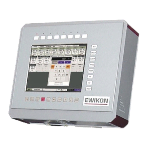
Page 5: Display Elements And Controls
Display elements and controls The PC version is controlled via 26 membrane keys arranged around the display and varying dialog boxes on the touch sensitive screen surface. Menu selection via screen or corresponding function keys Zone window Status bar No. Name Function ON / OFF Switch the hotrunner system on and off... -
Page 6: Connection And Putting Into Service
Connection and putting into service Control panel, Art No. 68010.300 Numeric keypad Function keys Controller 24-zone 230V, Art No. 68010.324 8 or 4-zone Unit - controller module, address switch top zone 1-12 bottom zone 13-24 Control circuit Fuse, F 6.3A Zone fuse, F 12.5A LEDs for status display... - Page 7 The figures on the page on the left show an example of a 24-fold controller 230V with external control panel. The PC control is connected analogous to the control panel, irrespective of whether it is realised as a controller rack or wall-mounted device. To avoid problems, the following procedure should be followed to start up the control system: •...
-
Page 8: Operating The System
Operating the system Introduction The HPS-C control system with control monitor is controlled using 26 surrounding keys and the corresponding buttons on the touchscreen surface. All the settings for the control system can be entered in the various menus described in detail in the following text. -
Page 9: Display" Menu
"Display" menu Display After switching on and starting up the control system the program starts in the Display menu. Up to 40 zones per page are displayed as single windows with the most important process information. If there are a larger number of zones (max. 160) the other pages can be opened using the cursor keys. -
Page 10: Zone Selection / Grouping
Zone selection / grouping The set value can only be adjusted in the Display menu if the relevant zones have been selected beforehand. The selected zones are marked with a green frame, in order to enable them to be more quickly identified. Both single and several or all zones can be selected or grouped. -
Page 11: Zone Selection / Grouping
"Table" menu Display Unlike the "Display" menu, all zones are displayed row by row in tabular form. Apart from the most important process data; actual temperature, set value and output power, other values are also available. The display is intended as an alternative to single window display and if the operator wishes can be equally used. -
Page 12: Parameter" Menu
"Parameters" menu Display The basic configuration of the controller for the respective application is set in the "Parameters" menu; information about the zone status is also available here. The zone number, zone name, position within the control system and the operating mode setting are displayed in the upper part of the screen. -
Page 13: Zone Labelling
Zone labelling After touching the display field for the zone name the input window shown below appears. The zones are given explanatory names (nozzle 1-n, manifolds 1-n ...) for faster orientation in a high cavity system. These names can be approx 10 characters long and are used in all the menus. -
Page 14: Extended Functions After Entering Password
Extended functions after password entry After entering the correct password, experienced operators can also make further adjustments. The password is entered in the "Options" menu and is described in the chapter with the same name. The additional functions displayed below are available on the next higher access level (Level 1). - Page 15 Load type / control parameters The HPS-C control system is equipped with a PID control algorithm, which ensures optimum control performance and small deviations between the actual and set value during operation. During the system's heating phase other additional supporting special functions act (ramp, compound operation ...), as the connected controlled system (hotrunner) mostly behaves differently to the subsequent operation.
-
Page 16: Chart" Menu
"Chart" menu Display Apart from permanent data recording on the hard disk, 10 diagrams are available with touchscreen control, on which the important process data and their curves can be shown. These can then be used to query the trend or peak values of the last time interval. - Page 17 The settings for the time axis (X-axis) of the diagram are specified in the "recording" field. The interval specifies the cycle in seconds over which the data is recorded. The whole recorded duration of the diagram changes depending on the interval time, e.g.
-
Page 18: Utilities" Menu
"Utilities" menu Display A simple image viewing function is provided in this menu with which the graphic diagrams can be displayed in BMP or JPG file format. This enables mould views, wiring plans or other mould data to be directly saved on the PC. If necessary this information is then available to the user "online". -
Page 19: Parameter Settings
Parameter settings Values and functions which apply across the zones to all the controller modules can be changed or switched on and off in this submenu. Access is also divided into different authorisation levels, which are protected by a password. Password entry and access management are described in greater detail in the "Options"... -
Page 20: Startup Ramp / Heating-Up Speed (Level 1)
and at a maximum temperature (start-up temperature), after this the system starts with the set set-point value. The drying phase is prematurely aborted if: • The leakage current measurement detects there is no moisture in the hotrunner system. • All temperature values in the hotrunner system were over 120°C when the system was switched on. Startup ramp / heating-up speed (Level 1) When the hotrunner system is switched on or in case of set value changes, the set gradient determines the speed (change per second), with which the system is to change to the new set value. -
Page 21: System Status / Error Messages
System status / error messages • "ON" Hotrunner is ON (1 = heating mode) or OFF (0 = Standby) • "IN" Increase mode is switched on (1) or switched off (0) • "DE" Decrease mode is switched on (1) or switched off (0) •... -
Page 22: Options" Menu
"Options" menu Access authorisation and the display layout of the PC controls is managed in the "Options" menu, several special functions can also be set here. Access through various password levels is also controlled here; with authorisation "Level 0" information only can be opened, changes can only be made from "Level 1". Diverse setting and adjustment options appear on the interface depending on the access levels set. -
Page 23: Even Heat Up Mode
Even heat up mode When this function is switched on, after the automatic "self-optimization" and "drying" start functions have been completed all zones are heated with uniform temperature level. During this phase the corresponding display appears in the system status field, further the current temperature set value for all zones is displayed. -
Page 24: Windows Interface
Log (Level 2) The "Log" button is used to generate a tabular list of all manual changes and inputs made to the controls since the program start. When the program is quit this information is saved as a file in the "Log" subdirectory of the program directory from where it can be exported for subsequent evaluations. - Page 25 USB connections with installed memory stick LAN connection Fuse Power supply The directory with the control program for the HPS-C controller is located on the computer's "D" drive under the name "HPS- C-TS". Under this are the program and driver files and further subdirectories in which the various files are saved by the program or have to be imported by the operator.
-
Page 26: Specifications
Specifications HPS-C controllers Operating voltage: 230V / 400V +6/-10%; 50 / 60 Hz Degree of protection: IP 33 Output power: 230V: = 2500VA per zone or P = 3500VA per zone = 625VA per zone (transformer dependent) Output signal: 230V: Phase-fired in drying, pulse packet in normal operation Phase-fired Fuse:... - Page 27 HPS-C - TS touchscreen control • 10.4“-SVGA – LCD with touch surface, resolution 800 * 600 pixels • 26 surrounding membrane keys for often used functions • CPU 266MHz with 64 MB RAM • 10 GByte hard disk • 2 * CANopen interface •...
-
Page 28: Connector Pin And Terminal Assignment
Connector pin and terminal assignment 24 V DC signal socket Contact / Wire Name Decrease Input 1 Input 2 Increase Input 3 Not used Input 4 Not used Output 1 Fault message Output 2 Warning message Output 3 Hotrunner ON Output 4 Not used + 24 V DC... - Page 29 5V power circuits Zone Connection HPS-C - TS operating instructions Page 29 / 32...
- Page 30 230V load connection 16-pin socket insert for up to 8 heaters Zone Contact 1 + 9 2 + 10 3 + 11 4 + 12 5 + 13 6 + 14 7 + 15 8 + 16 24-pin socket insert for up to 12 heaters Zone Contact 1 + 13...
- Page 31 Temperature sensor connection 16-pin insert for up to 8 temperature sensors Contact Zone +red -blue 32-pin insert for up to 16 temperature sensors contact Zone +red -blue *) In controllers 68010.316 and 68010.364 the connector plug is completely assigned with 16 zones. In controllers with a larger number of zones the other connector plugs are assigned according to the first connector plugs.
- Page 32 EWIKON Heißkanalsysteme GmbH Siegener Straße 35 35066 Frankenberg Tel: (+49) 64 51 / 50 10 Fax: (+49) 64 51 / 50 12 02 E-mail: info@ewikon.com www.ewikon.com...
Need help?
Do you have a question about the HPS-C-TS and is the answer not in the manual?
Questions and answers