Table of Contents
Advertisement
Quick Links
Advertisement
Table of Contents

Related Manuals for EWIKON pro CONTROL basic


Summary of Contents for EWIKON pro CONTROL basic
- Page 1 Hot runner controllers Operating manual...
-
Page 2: Table Of Contents
Selecting multiple zones 5.1.3 Selecting several consecutive zones 5.1.4 Selection of all zones Operating mode Setpoints Output rate Controller outputs Parameter 5.6.1 Zone parameter 5.6.2 System parameter Boost Standby page 2 pro CONTROL BASIC hot runner controllers – Operating manual... - Page 3 Appendix ........................38 11.1 Terminal bridges of the star-delta supply 11.1.1 Terminal jumpers in star network (state at delivery!) 11.1.2 Terminal bridges in delta network 11.2 Notification contact / Digital input page 3 pro CONTROL BASIC hot runner controllers – Operating manual...
-
Page 4: Introduction
4 pro CONTROL BASIC hot runner controllers – Operating manual... -
Page 5: Structure And Functionality
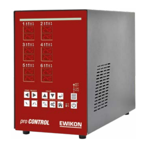
2 or 6 heating zones. Structure Housing front: The pro CONTROL BASIC hot runner controller is operated from the housing front with 12 keys. Furthermore, the front contains all visualization elements. The setpoint and actual values of the individual zones are displayed via 7-segment displays. -
Page 6: Pro Control Basic 2 Und 6 Zonen
The convenient operation of the pro CONTROL BASIC hot runner controller is carried out on the front panel (Figure 1 - pro CONTROL BASIC front panel) via 12 keys. The front also con- tains all visualization elements. The setpoints and actual values of the individual zones are displayed via 7-segment displays. -
Page 7: Notification Contact / Digital Input
CONTROL BASIC Manual 3.2.6 Notification contact / Digital input The pro CONTROL BASIC hot runner controllers have a potential-free message contact and a digital control input, which are brought out via a 7-pin plug on the rear of the unit. A contact diagram of the built-in plug is given in chapter 11.2Fehler! Verweisquelle konnte nicht ge-... -
Page 8: Wiring Of The Plug Systems
(see Figure 6 for an example). Load Sensor ̴ Zone 230 V Table 1 – 2-zone plug Load Sensor ̴ Zone 230 V Table 2 – 6-zone plug page 8 pro CONTROL BASIC hot runner controllers – Operating manual... -
Page 9: Commissioning
Important! To exclude any effects of potential shifts, the injection molds that are connected up must be properly earthed in all cases. page 9 pro CONTROL BASIC hot runner controllers – Operating manual... -
Page 10: Operating And Display Elements
The following illustration shows the front view of a 6- zone controller, from which all operating and display elements are shown. Figure 3 – Operating and display elements page 10 pro CONTROL BASIC hot runner controllers – Operating manual... -
Page 11: Display Elements
In addition, the four LEDs can also be used to display the states shown below. Figure 4 – Zone display page 11 pro CONTROL BASIC hot runner controllers – Operating manual... -
Page 12: Operating Elements
Change in value Confirm button / Acknowledge error Boost Standby Change operating mode Parameterization / System information Basic view: Display of all zones / Reject input page 12 pro CONTROL BASIC hot runner controllers – Operating manual... - Page 13 Shift key for the zone display Display: Actual value (ACT) and setpoint (SET) Display: Current (I[A]) and output level (Y[%]) Activating / deactivating the controller outputs Temperature unit of the display page 13 pro CONTROL BASIC hot runner controllers – Operating manual...
-
Page 14: Operation
Step Operation Description Selection of the 1st zone to be selected Keep confirmation key pressed With each keystroke a zone is added to the selection Release the confirmation key page 14 pro CONTROL BASIC hot runner controllers – Operating manual... -
Page 15: Selection Of All Zones
Note: The display flashes and must be confirmed within 5 seconds. Confirm the entry The display stops flashing Press the Home button to return to the overall display of all zones. page 15 pro CONTROL BASIC hot runner controllers – Operating manual... -
Page 16: Setpoints
The display flashes, indicating that the value has not yet been accepted. Confirm the entry The display stops flashing Press the Home button to return to the overall display of all zones. page 16 pro CONTROL BASIC hot runner controllers – Operating manual... -
Page 17: Output Rate
Controller outputs Step Operation Description Activating / deactivating the controller outputs either switches on all heating zones in control mode and manual operation or switches off all zones. page 17 pro CONTROL BASIC hot runner controllers – Operating manual... -
Page 18: Parameter
The display flashes. This means that the value has not yet been accepted. Confirm the entry. The display stops flashing. Press the Home button to return to the overall display of all zones. page 18 pro CONTROL BASIC hot runner controllers – Operating manual... -
Page 19: System Parameter
The display flashes, indicating that the value has not yet been accepted. Example: System parameter with value 500 Confirm the entry. The display stops flashing. Press the Home button to return to the overall display of all zones. page 19 pro CONTROL BASIC hot runner controllers – Operating manual... -
Page 20: Boost
The standby mode terminates the boosting if necessary. The standby mode can also be activated via the digital 24V control input. The setpoint display SET flashes alternating with the dis- play „Stb“. page 20 pro CONTROL BASIC hot runner controllers – Operating manual... -
Page 21: Warning And Error Messages
CONTROL BASIC Manual Warning and error messages The pro CONTROL BASIC controllers provide information about the current status via status and 7-segment display. Warnings and alarms are shown as abbreviations in the 7-segment display. In addition, the LED band indicates the controller status in green, yellow and red. In the standard state, the LED band lights up green. -
Page 22: Alarms
) is too close to the Alarm is setpoint displayed Heat output may not be sufficient Heating could be defective Sensor not in contact with this zone Sensor polarity reversal Controller is heating up page 22 pro CONTROL BASIC hot runner controllers – Operating manual... - Page 23 Sensor voltage • The voltage potential on the sensor cable is im- permissibly high Alarm is displayed Wiring error Cable or plug defective Cable pinching page 23 pro CONTROL BASIC hot runner controllers – Operating manual...
- Page 24 Line pinch CAN-Bus fault • Communication error of the internal power card Alarm is displayed Identical address assigned twice Cable not connected correctly Missing final resistance of the last participant page 24 pro CONTROL BASIC hot runner controllers – Operating manual...
-
Page 25: Functions And Parameterization
Parameter System parameter Settings 0…999, Default value = 22 ID Code ID Level 0…2, Default value =1 (read only, value cannot be ID Pin Code changed) page 25 pro CONTROL BASIC hot runner controllers – Operating manual... -
Page 26: Fahrenheit Display
Parameter System parameter Settings Fe/CuNi Typ J Ni/CrNi Typ K with tempera- Thermocouple type ture range max. 800°C Default value = 0 page 26 pro CONTROL BASIC hot runner controllers – Operating manual... -
Page 27: Control Behaviour
7.2.3 Maximal output level This parameter limits the maximum output power of the heaters via the Description output level. Parameter Zone parameter Settings 0…100% Maximal output level Default value: 100% page 27 pro CONTROL BASIC hot runner controllers – Operating manual... -
Page 28: Heating
20° C. Zones 5 and 6 should not be part of the heating compound. The settings: Zone 1 to zone 4: Parameter Zone 5 and Zone 6: Parameter System parameter = 20 page 28 pro CONTROL BASIC hot runner controllers – Operating manual... -
Page 29: Hot Runner Monitoring
1…600°C (800°C for NiCrNi as Thermo- Hi-Alarm couple) Default value: 400°C dL / dH 1…600°, Default value: 15°C Tolerance band System parameter 0…600°C (800°C for NiCrNi as Thermo- HH-Alarm couple) Default value: 400°C page 29 pro CONTROL BASIC hot runner controllers – Operating manual... - Page 30 Hi-Alarm 250°C dL / dH 15°C Tolerance band System parameter HH-Alarm 400°C The following figure illustrates the relationships: Hi-Alarm = 250° Lo-Alarm = 150° Figure 5 – Temperature monitoring page 30 pro CONTROL BASIC hot runner controllers – Operating manual...
-
Page 31: Average Output Level
The current measurement monitors the value of parameter with this toler- ance. Parameter Zone parameter Settings 0,0…25,0A, Default value=0,0A Current: Reference value 0,0…16,0A, Default value=0,5A Current: Tolerance page 31 pro CONTROL BASIC hot runner controllers – Operating manual... -
Page 32: Triac Monitoring
- the boost offset (parameter ) - for a certain time (parameter The control is carried out via the "Boost button". Parameter Zone parameter Settings 0…50K, Default value=0K Boost-Offset 0…900s, Default value=60s Boost-Duration page 32 pro CONTROL BASIC hot runner controllers – Operating manual... -
Page 33: Standby
With this parameter a reset of all settings to the factory setting can be initiated. 1 = Load default parameters Parameter System parameter Settings 0, 1 Default parameter Default value: 0 page 33 pro CONTROL BASIC hot runner controllers – Operating manual... -
Page 34: Parameter Overview
Lowering the temperature to a new set 7.5.2 Standby temperature point Average output level The average output level (Read Only) 7.4.2 Classification of zone Found classification (Read Only) 7.2.1 page 34 pro CONTROL BASIC hot runner controllers – Operating manual... -
Page 35: System Parameter
Shows the current temperature of the Temperature thermocouple terminal on the power Thermo-Terminal card Shows the current software version of Software Version the firmware page 35 pro CONTROL BASIC hot runner controllers – Operating manual... -
Page 36: Technical Data
4A at cos = 1; 2A at cos = 0,5 13 – 30V DC Digital input - isol. potential free : Depth gauge without mold connection : at an air temperature of 20°C page 36 pro CONTROL BASIC hot runner controllers – Operating manual... -
Page 37: Spare Parts + Accessories
General spare parts / General accessories Description Item number 60070.046 Signal cable pro CONTROL BASIC DigiIn/Out, L = 6 m 18401 Fuse holder cap pro CONTROL 18402 Fuse pro CONTROL 16 A(gRL) 6.3 x 32 mm 18403 Fuse pro CONTROL 16 A (T) 6.3 x 32 mm... -
Page 38: Appendix
11.1.2 Terminal bridges in delta network Figure 7 - Delta-network 11.2 Notification contact / Digital input Contact Function 1.+3. Notification contact Normally closed Digital input 0V Standby Digital input 24V Standby page 38 pro CONTROL BASIC hot runner controllers – Operating manual... - Page 39 Safety requirements for electrical equipment for measurement, control and laboratory use DIN EN 61326-1:2013-07 Electrical equipment for measurement, control and laboratory use - EMC requirements Frankenberg, 14 November 2019 Dr. Stefan Eimeke Managing Director pro CONTROL BASIC hot runner controllers – Operating manual...
- Page 40 EWIKON Heißkanalsysteme GmbH Siegener Straße 35 35066 Frankenberg Tel: +49 6451 / 501-0 Fax: +49 6451 / 501 202 E-mail: info@ewikon.com www.ewikon.com...
Need help?
Do you have a question about the pro CONTROL basic and is the answer not in the manual?
Questions and answers