
Subscribe to Our Youtube Channel
Related Manuals for EWIKON motion CONTROL SD


Summary of Contents for EWIKON motion CONTROL SD
- Page 1 Controller for electric valve gate systems valid for item numbers: with single linear servo drives 68152.202 68152.204 68152.208 from software version 1.00.0 Operating manual EWIKON 01/2022...
- Page 2 2022_01_Operating manual_motion CONTROL SD_EN.indd...
-
Page 3: Table Of Contents
Standards and directives ............................14 Technical Data ................................ 15 Mechanical data ............................... 15 3.1.1 Main dimensions / Dimensions of the motion CONTROL SD controller ..............15 Electrical data ................................15 3.2.1 Connections / Connector pin assignment ........................ 15 Operating conditions ..............................15 Placing the controller ............................... - Page 4 6.3.1 Connections and connector assignment of a 4-zone controller ................22 6.3.2 Connecting the motion CONTROL SD controller to the injection moulding machine ..........23 6.3.3 Connecting the motion CONTROL SD controller to the mould ................25 Checks after assembly ............................25 Start up ...................................
- Page 5 Safety instructions for maintenance ......................... 47 Maintenance work ..............................48 9.3.1 Changing the filter ..............................48 9.3.2 Cleaning the motion CONTROL SD controller ....................... 48 9.3.3 Checking fan or fan grille ............................48 Service and repair instructions ..........................48 Decommissioning ..............................49 10.1...
-
Page 6: General Information
You must carefully read this operating manual and familiarise yourself with the safety installations before installing, commissioning or maintaining the device. Do not operate the device without having received appropriate training. 1.1 Information on this operating manual These operating manual has been prepared in accordance with directive 2006/42/EC. It enables the safe and efficient operation of motion CONTROL SD controllers. 1.2 Manufacturer EWIKON Heißkanalsysteme GmbH Siegener Straße 35 35066 Frankenberg... -
Page 7: Conventions
1.4 Conventions 1.4.1 Instructions and system responses Operating steps that have to be carried out by the operator are displayed as a numbered list. The sequence of the steps has to be adhered to. Example: 1. Operating step 1 2. Operating step 2 1.4.2 Enumerations Enumerations without mandatory sequence are displayed as a list with bullet points. -
Page 8: Safety Instructions
2. Safety instructions The motion CONTROL SD controller complies with the Low Voltage Directive 2014/35/EU and the EMC Directive 2014/30/EU and has been designed, manufactured and tested for safety in accordance with the currently applicable safety regulations and laws and the state of the art. If the motion CONTROL SD controller is used in a manner not specified by EWIKON, the function of the protective devices of the device may be impaired. -
Page 9: Signal Words For Hazard Classification
2.1.1 Signal words for hazard classification HAZARD Indicates an imminently hazardous situation which, if not avoided, will result in death or serious injury. WARNING! Indicates a potentially hazardous situation which, if not avoided, will result in death or serious injury. CAUTION Indicates a potentially hazardous situation which, if not avoided, will result in minor injury or material damage. -
Page 10: Intended Use
Any other use contrary to the intended use is excluded and may lead to personal injury and damage to material. In this case, the warranty expires. The motion CONTROL SD controller is to be used exclusively for controlling the valve pin movement of EWIKON valve gate hot and cold runner systems installed in a closed injection mould. -
Page 11: Hazards And Safety Measures In Connection With Hot Runner Systems
Always wear the following when carrying out special work: Safety glasses: To protect your eyes Ear protection: To protect your ears against scattering debris, heat and melt against loud ambient noises. splashes. Face mask: To protect your face against Protective helmet: To protect your head scattering debris, heat and melt splashes. - Page 12 Risk of electric shocks • Danger to life by electric shock. Touching live surfaces may result in severe or even lethal injuries. • Always keep water away from live components and the hot runner. There is a risk of short circuits! Safety measures •...
-
Page 13: Electrical Equipment
Provide protection against adjacent live parts Maintenance work must be carried out by qualified and trained staff or maintenance staff in accordance with DIN EN 61010-2-201. Never use the motion CONTROL SD controller with faulty or inoperable electrical connections. In case of energy supply disruptions immediately switch off the motion CONTROL SD controller. The maintenance & in- spection schedules regarding electrical components given by the manufacturers have to be adhered to. Check for damaged insulation at regular intervals. -
Page 14: Warranty Terms
2.10 Warranty terms For warranty conditions of hot runner systems and components please refer to the terms and conditions of EWIKON. 2.11 Standards and directives EWIKON hot runner systems conform to the following European directives: • Machinery Directive 2006/42/EC •... -
Page 15: Technical Data
Dimensions (H x B x T) 460 x 220 x 550 Item no. 68152.208 Weight approx. 21 Chart 2: Main dimensions / Dimensions of the motion CONTROL SD controller 3.2 Electrical data 3.2.1 Connections / Connector pin assignment Description Qty. / size (approx.) -
Page 16: Placing The Controller
3.4 Placing the controller Place the controller on a stable, flat, non-combustible working surface. The display should be at eye level with the user to facilitate reading of the display and operation of the device. The device includes a built-in fan on the rear side as well as ventilation slots on the underside, protected by a filter. Make sure that the air flow through these openings is not obstructed. Keep a minimum distance of 0.2 m in all directions around the device to other equipment and parts of buildings. 0.2 m 0 . 2 m 0.2 m 2022_01_Operating manual_motion CONTROL SD_EN.indd... -
Page 17: Functional Description Of The Motion Control Sd Controller
Chart 5: Connecting cables required for the motion CONTROL SD controller (not included in delivery!) 4.3 Function The motion CONTROL SD controller enables precise control of the opening and closing movement for electric valve gate systems, especially for sequential gating. Depending on the version, two, four or eight drives can be connected to one motion CONTROL SD controller. Only linear actuators (servo motors with integrated spindle) qualified by EWIKON can be... -
Page 18: Operating Instructions
Risk of electric shock due to live parts and risk of severe injuries due to moving parts • Ensure zero potential before performing any work on or inside the motion CONTROL SD controller • Set the power switch to OFF and disconnect the mains plug •... -
Page 19: Operating Requirements
(0 V), the valve pins close again. If the trigger signal is not made available by the controls of the in- jection moulding machine as described, an adjustment will have to be made. Further digital or analogue signals can be used to obtain e. g. complex motion profiles. The motion CONTROL SD controllers are exclusively designed for the drives mentioned below. Item no. Description... -
Page 20: Assembly
6.2 Checks before installation The motion CONTROL SD controller is subject to comprehensive testing by the manufacturer before delivery. For safety reasons (transport or storage damage or damage to the device when preparing installation) we recommend that you check the motion CONTROL SD controller for damage just before installing it. - Page 21 2022_01_Operating manual_motion CONTROL SD_EN.indd...
-
Page 22: Installation
6.3.1 Connections and connector assignment of a 4-zone controller Depending on the model, not all or more connections are available. Picture 2: Connections on the front side of the motion CONTROL SD controller Picture 3: Connections on the rear side of the motion CONTROL SD controller... -
Page 23: Connecting The Motion Control Sd Controller To The Injection Moulding Machine
Mains connection Mains cable, operating voltage 230 V +10/-15%, 50-60 Hz Chart 7: Connections of the motion CONTROL SD controller 6.3.2 Connecting the motion CONTROL SD controller to the injection moulding machine CAUTION! Insulation of unused cores Failure to do so may result in damage to the device. - Page 24 Digital output It is highly recommended to connect the digital signal output of the controller to the injection moulding machine to detect when the control is „ready“ for the next cycle or when there is an error. Each signal output provides +24 V DC and can be loaded with 0.1 A.
-
Page 25: Connecting The Motion Control Sd Controller To The Mould
The motion CONTROL SD controller is connected to the drives via the orange hybrid connection cable, item no. 63050.130 (3 m) or 63050.130-V06 (6 m). Other lengths are available on request. The hybrid connection cable is specially designed for this application due to its shielded construction and is ready to plug in at both ends. -
Page 26: Start Up
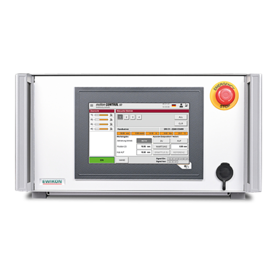
Picture 6: Front view of the motion CONTROL SD controller The motion CONTROL SD controller for the control of electrically operated valve gate systems by means of servo actuators is equipped with a colour touch-screen display via which all settings can be made. -
Page 27: Description Of The Menus
„I/O test“ function (see chapter „7.2.6.3 I/O Test“). The menu selection is made via the hamburger menu at Picture 7: Start page of the motion CONTROL SD controller the top left. Picture 8: Process values with menu open Menu selection: •... -
Page 28: Screen Layout
7.2.2 Screen layout Title bar Input and display window Selection bar Picture 9: Screen layout of the motion CONTROL SD controller Title bar Menu selection Area for additional information Language selection (DE / EN / ITA / PL) Name of the currently selected menu... - Page 29 Diagram with details (position, Signal outputs (Signal Out): speed, current, torque) of a drive plus optional analogue • Output 1 indicates an alarm in the motion CONTROL SD signals system to the injection moulding machine. Output 2 is configurable in the menu „Setup System & • Device; General“ if required (by default to „READY for next Cycle“) and is usually used to enable the machine.
-
Page 30: Operation
7.2.3 Operation In the „Overview“ window, the actual position of each drive is displayed via orange bars, the display is scaled to the maximum stroke of the selected drive. • Bar on the right = needle in rear position (OPEN) •... -
Page 31: Automatic Operation
The toggle button simultaneously displays the unit of the physical quantity in the lower left corner. In the detailed view, the position profile, the speed, the current, the torque and the measured value at the analogue inputs of the motion CONTROL SD controller are displayed separately for one drive. By touching the bar of the respective drive in the overview, the view is switched between the drives. -
Page 32: Error Messages Of The Servo Controller
7.2.3.3 Error messages of the servo controller Picture 13: Servo controller error message; no connection to the Picture 14: Servo controller error message; positioning error drive In „Manual“ mode, error messages from the servo controller are displayed in the individual view with error ID and descripti- on. The errors must be acknowledged via the confirmation button (grey tick) when the drive is switched on. As a rule, 2 - 3 related error messages occur. -
Page 33: Configuration Of Drives
7.2.4 Configuration of drives In the selection bar it is possible to navigate through the settings. Changes to most settings are only possible after entering a higher access level (see chapter „7.2.5.2 Display & View“). 7.2.4.1 General (basic settings) ATTENTION: The settings for „Type of Drive“, „Operating Mode“, „... -
Page 34: Motion (Motion Profile Setting)
7.2.4.2 Motion (Motion profile setting) Picture 16: View „Configuration of drives – Motion Profile“ The settings for the trigger events can be entered here. The following parameters can be set or selected for each step: • The position „OPEN“ as a numerical value in mm (here step 1) cannot be set, as this value is calculated via the set stroke (see chapter „7.2.4.1 General (basic settings)“) •... -
Page 35: Monitoring
7.2.4.3 Monitoring Picture 17: View „Configuration of drives – Monitoring“ Attention! All settings on this page are only possible when the drives are switched off! Lag Error Warning Maximum deviation from ACTUAL / NOMINAL during the movement until a warning is issued. Fault Counts „Error Signal“ Number of position errors in a row after which an error is reported to the injec- tion moulding machine Number of position errors in a row after which a drive is switched off to avoid... -
Page 36: Options (Optional Settings)
7.2.4.5 Extended (Extended settings) Picture 19: View „Configuration of drives – Extended Settings“ Changes to these settings can have a serious effect on the driving behaviour of the drive and the actuated mechanics and may therefore only be carried out by EWIKON specialised personnel. 2022_01_Operating manual_motion CONTROL SD_EN.indd... -
Page 37: Setup System & Device
7.2.5 Setup System & Device In the selection bar it is possible to navigate through the settings. Changes to most settings are only possible after entering a higher access level (see chapter „7.2.5.2 Display & View“). 7.2.5.1 General Picture 20: View „Setup System & Device – Functions of Device“ Function Digital Output Selection of the function of the digital outputs for adaptation to the process: 2, 3 and 4... -
Page 38: Display & View
7.2.5.2 Display & View Picture 21: View „Setup System & Device – Display & View“ In diesem Menü können folgende Einstellungen vorgenommen werden: Date Setting the date Time Setting the time Brightness Setting the display brightness Calibrate Touchpad If the touch screen no longer responds correctly to inputs, there is the possibility of calibration Device Temperature Display of the device temperature... -
Page 39: Network
7.2.5.3 Network Picture 22: View „Setup System & Device – Network“ If the device is to be integrated into a network, the necessary network settings can be made here, for example for access via OPC UA or remote control of the device via VNC. 7.2.5.4 Analog IN Picture 23: View „Setup System & Device – Analog IN“... -
Page 40: Opc Ua Id
7.2.5.5 OPC UA Id Picture 24: View „Setup System & Device – OPC UA Id“ The settings for item no., serial no. and year of manufacture can only be made by EWIKON and are set during production. The device designation and the place of use can also be set by the customer via OPC UA access, e.g. via UA-Expert. -
Page 41: Diagnosis And Troubleshooting
7.2.6 Diagnosis and troubleshooting 7.2.6.1 Alarms Picture 26: View „Diagnosis and troubleshooting – Alarms“ Detailed view of the current alarms with date, time, output, alarm type and alarm text for more detailed analysis. The arrow keys on the right edge can be used to scroll through the view. Acknowledgement of an error is done via the confirmation button (grey tick). -
Page 42: I/O Test
Access level 2 is required to set the outputs. 7.2.6.4 System Diagnostics Manager (SDM) Picture 29: View „Diagnosis and troubleshooting – System Diagnostics Manager“ This menu is used by EWIKON for internal analyses during troubleshooting and is only released from access level 2. 2022_01_Operating manual_motion CONTROL SD_EN.indd... -
Page 43: File Management
7.2.7 File management 7.2.7.1 Internal Picture 30: View „File management – Internal Memory“ This menu allows the settings for up to 50 different tools to be saved in the internal memory or loaded from there (drive (F:) in the device memory). The folder „Backup“ as well as alarm lists, screenshots and record files can be present on this drive. Saves new mould settings after entering the file name SAVE AS Applies changes by overwriting the selected old file SAVE Loads the settings of the selected file into memory for execution LOAD Deletes the selected recipe file DELETE To save, load or delete (access level 1) saved settings, a file must be selected using SAVE / LOAD / DELETE the arrow keys (it appears with an orange background). The selected operation must be confirmed by acknowledging a confirmation prompt. Copies the selected file to the external memory when a USB stick is connected (see COPY TO USB chapter „7.2.7.2 External USB“). -
Page 44: Report
Access to the system memory is also possible with an FTP client programme via the RJ45 connection in conjunction with an Ethernet cable on a computer network (please ask EWIKON for terminal settings and access data). 2022_01_Operating manual_motion CONTROL SD_EN.indd... -
Page 45: Help In Case Of Malfunctions
Fuse 6.3 A (M) 5 x 20 mm (in module X20PD2113) Chart 11: Spare parts list 7.3.3 EWIKON service departments For service enquiries, please always have the article number and the current software version of the present device (OPC UA Id) as well as the order number (also that of the hotrunner system) ready! •... -
Page 46: Quick Start Guide
8. Quick Start Guide CAUTION! Incorrect settings can lead to incorrect function or even damage to the mould or the drives! The operation of the motion CONTROL SD controller is divided into several access levels. • Level 0 Operator (start level) •... -
Page 47: Service And Maintenance
In order to ensure a long service life and trouble-free operation of the motion CONTROL SD controllers, proper care and maintenance are required in addition to correct operation. In addition to inspection and repair, maintenance is a preventive measure for the upkeep of the motion CONTROL SD controllers. -
Page 48: Maintenance Work
These static patterns cause parasitic capacitances inside the LCD components preventing the liquid crystal molecules from returning to their original state. To reduce this effect we recommend that you switch off the motion CONTROL SD controller when not in use. -
Page 49: Decommissioning
Risk of death by electric shock or severe injuries caused by live components • Please make sure that you have disconnected the motion CONTROL SD controller from the voltage sup- ply before dismantling it. At first remove the power cable to prevent any connection to the power supply, then all plug-in connections to mould or machine have to be removed from the device. - Page 50 2022_01_Operating manual_motion CONTROL SD_EN.indd...
-
Page 51: Ec - Declaration Of Conformity
EC - Declaration of Conformity... - Page 52 EWIKON Heißkanalsysteme GmbH Siegener Straße 35 35066 Frankenberg Tel: +49 6451 / 501-0 Fax: +49 6451 / 501 202 E-Mail: info@ewikon.com www.ewikon.com...
Need help?
Do you have a question about the motion CONTROL SD and is the answer not in the manual?
Questions and answers