Table of Contents
Advertisement
Quick Links
PENN | TC3B23N5V-004 | Installation Guide Rev. — | Part No. A163825YEM | Page 1 of 2 | 5 September 2023
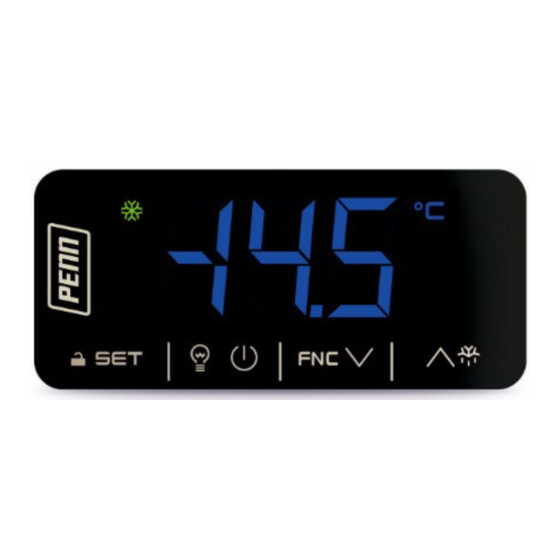
TC3B23N5V-004
Features
-
Controller for low temperature units
-
Power supply of 115 VAC
-
Cabinet probe and auxiliary probe, with negative temperature coefficient (NTC)
-
Door switch or multi-purpose input
-
Compressor relay with 16 A resistive load at 250 VAC
-
Cooling or heating operation
Dimensions and installation
Installation precautions
-
Ensure the panel's thickness is between 1/32 in. and 1/16 in. (0.8 mm and 2.0 mm).
-
Ensure that the working conditions are within the limits stated in
specifications.
-
Do not install the controller close to heat sources, equipment with a strong magnetic
field, in places subject to direct sunlight, rain, dampness, excessive dust, mechanical
vibrations, or shocks.
-
Install the controller in compliance with safety regulations to ensure adequate
protection from contact with electrical parts. Fix all protective parts in such a way that
you need a tool to remove them.
Dimensions are in mm (in.). Fit the controller to a panel with the supplied snap-in brackets.
Wiring
Important
- Use cables with an adequate cross section for the current that runs through them.
- Connect the power cables as far away as possible from the signal cables, to reduce
electromagnetic interference.
Wiring precautions
-
If you use an electrical or pneumatic screwdriver, adjust the torque to a maximum of 4
in. lb (0.5 N•m).
-
If you move the controller from a cold to a warm place, the humidity may cause
condensation to form inside. Wait an hour before you switch on the power.
-
Make sure that the supply voltage, electrical frequency, and power are within the set
limits. See
Technical
specifications.
-
Disconnect the power supply before you perform any type of maintenance.
-
Do not use the controller as a safety device.
-
For repairs and for further information, contact the PENN sales network.
First time setup
Note: The default password for the controller is -19.
1.
Install the controller in the panel. See
Dimensions and
2.
Wire power to the controller. See the power supply terminal in Wiring.
3.
Tap On/Standby to turn on the controller. An internal test runs for several seconds.
After the internal test, the display switches off.
4.
Configure the controller. See
Setting configuration parameters
following list contains some useful parameters to configure for first time setup:
-
Setpoint (SP), default: 32
-
Temperature unit of measurement (P2), default: °F
-
Defrost type (d1), default: electric
Note: Check that the remaining settings are also appropriate. See
parameters.
5.
Disconnect the controller from the power supply.
6.
Make the electrical connections without powering up the controller. See Wiring.
7.
Reconnect the power supply.
8.
Tap On/Standby to turn on the controller.
4
User interface and main functions
Switching the controller on or off
If POF is set to 1, tap the On/Standby key for 4 s. See
configuration
parameters.
When the controller is switched on, the display shows the value that the parameter P5
indicates. P5 is set to cabinet temperature by default. If the display shows an alarm code, see
Basic Defrost Controller Installation Guide
Basic controller for refrigerated cabinets with energy-saving strategies
LED
On
Compressor on
Defrost or pre-dripping active
Evaporator fan on
- If the controller is on,
energy saving active
- If the controller is off, low
consumption active
°C/°F View temperature
AUX
Auxiliary load on
Controller off
Key
Technical
If you do not press a key for 30 s, the screen displays Loc and the keypad locks automatically.
Unlocking the keypad
Tap a key for 1 s. The screen displays UnL. Unlock the keypad before you complete any task. If
a password is set, complete the following steps:
1.
If a password is set, tap the Up or Down key within 15 s to select the password.
See
Setting a
2.
Press the SET key.
Setting the setpoint
1.
Tap the SET key.
2.
Tap the Up or Down key within 15 s to set the value within the limits r1 and r2.
See
Configuration
3.
Tap the SET key or do not press a key on the keypad for 15 s.
Activating manual defrost
1.
Check that parameter r5 is set to 0 for cooling. r5 is set to 0 by default. See
Setting configuration
2.
Press the Up or Defrost key for 2 s.
Note: If P4 is set to 1, defrost only activates if the evaporator temperature is lower than the
d2 threshold. P4 is set to 1 by default.
Switching the cabinet light on and off
You can switch the K2 relay on or off if you configure and wire it for a cabinet light or a button-
operated load.
1.
Check that parameter u0 is set to 3 for cabinet light, or 1 for button-operated
load. u0 is set to 3 by default. See
2.
Tap the On/Standby key..
Note: The button-operated load does not switch on or off if the keypad is locked.
Additional functions
Viewing or deleting compressor functioning hours
1.
Press the Function or Down key for 4 s.
2.
Tap the Up or Down key within 15 s to select a label.
Label
CH
rCH
Tap the SET key.
3.
4.
If you selected rCH, tap the Up or Down key to set 149.
5.
Tap the SET key.
6.
To exit the procedure, tap the On/Standby key, or do not press a key on the
keypad for 60 s.
Viewing the temperature detected by the probes
1.
Press the Function or Down key for 4 s.
2.
Tap the Up or Down key within 15 s to select a label.
Label
Pb1
Pb2
3.
Tap the SET key.
4.
To exit the procedure, tap the On/Standby key, or do not press a key on the
keypad for 60 s.
Settings
Setting a password
Press the SET key for 4 s. The screen displays PA.
1.
2.
When PA displays, tap the SET key.
3.
Tap the Up or Down key within 15 s to select the password (PAS) value that you
installation.
want. The default password is -19.
4.
Tap the SET key.
Setting configuration parameters
in Settings. The
1.
After you unlock the keypad, tap the SET key. The screen displays SP.
2.
Tap the Up or Down key to select a parameter.
Tap the SET key.
3.
4.
Tap the Up or Down key within 15 s to set the value.
5.
Tap the SET key.
Configuration
6.
Tap the SET key for 4 s or do not press a key on the keypad for 60 s to exit the
procedure.
Restoring the defaults, and storing customized default settings
Important
- Check that the factory settings are appropriate. See
- If you store customized default settings, you overwrite the factory defaults.
Before you begin, if you want customized defaults, set the controller parameters to the values
that you want as defaults.
1.
After you unlock the keypad, press the SET key for 4 s. The screen displays PA.
2.
When PA displays, tap the SET key.
Tap the Up or Down key within 15 s to set the value.
3.
Label
149
161
4.
Tap the SET key. For restoring the defaults, the screen displays dEF. For storing
customized defaults, the screen displays MAP.
5.
Tap the SET key.
6.
Tap the Up or Down key within 15 s to select the value 4.
7.
Tap the SET key. The screen flashes with - - - for 4 s. After this, the controller
exits the procedure.
8.
Interrupt the power supply to the controller. This saves your changes.
Note: To exit the procedure without making a change, press the SET key for 2 s before you
select the value 4.
Setting
Off
Flashing
Compressor off
- Compressor protection active
- Setpoint setting active
—
- Defrost delay active
- Dripping active
Evaporator fan off
Evaporator fan stop active
—
—
—
—
Auxiliary load off
—
Controller on
Controller on/off active
Key function
SET
On/Standby
Up or Defrost
Function or Down
password.
parameters.
parameters.
Setting configuration
parameters.
Description
View compressor functioning hours, in hundreds
Delete compressor functioning hours
Description
Cabinet temperature
Auxiliary temperature
Configuration
Description
Value to restore the defaults
Value to store your customized settings as the defaults
Configuration parameters
Label
Default Setpoint
SP
32
Setpoint
Label
Default Analog inputs
CA1
0
Cabinet probe offset
CA2
0
Auxiliary probe offset
P0
1
Probe type
P1
1
Enable °C decimal point
P2
1
Temperature unit of
measurement
P4
1
Auxiliary probe function
P5
0
Value displayed
P8
5
Display refresh time
Label
Default Control
2
r0
Setpoint differential
r1
-50
Minimum setpoint
r2
100
Maximum setpoint
0
r4
Setpoint offset in Energy saving
mode
r5
0
Cooling or heating operation
r12
0
Position of the r0 differential
Label
Default Compressor
C0
0
Compressor on delay after
power-on
3
C2
Compressor off minimum time
C3
0
Compressor on minimum time
C4
10
Compressor off time during
cabinet probe alarm
C5
10
Compressor on time during
cabinet probe alarm
176
C6
Threshold for high condensation
warning
C7
194
Threshold for high condensation
alarm
C8
1
High condensation alarm delay
Label
Default Defrost, if r5 is set to cooling
8
d0
Automatic defrost interval
Note: If d8 is set to 3, the
automatic defrost interval is
always 99 h.
d1
0
Defrost type
d2
46
Threshold for defrost end
30
d3
Defrost duration
d4
0
Enable defrost at power-on
d5
0
Defrost delay after power-on
d6
2
Value displayed during defrost
d7
2
Dripping time
d8
0
Defrost interval counting mode
0
d9
Evaporation threshold for
automatic defrost interval
counting
0
d11
Enable defrost timeout alarm
d15
0
Consecutive time with
compressor on for hot gas
defrost
d18
40
Adaptive defrost interval
Note: If compressor on and
evaporator temperature < d22
d19
3
Threshold for adaptive defrost
Note: Relative to the
automatically calculated optimal
evaporation temperature
(Optimal evaporation
temperature - d19)
d20
180
Consecutive time with
compressor on for defrost
d22
2
Evaporation threshold for
adaptive defrost interval
counting Note: Relative to the
automatically calculated optimal
evaporation temperature
(Optimal evaporation
temperature + d22)
Label
Default Alarms
-20
A1
Threshold for low temperature
alarm
Note: Relative to setpoint (SP -
A1)
A4
20
Threshold for high temperature
alarm
Note: Relative to setpoint (SP +
A4)
A6
12
High temperature alarm delay
after power-on
parameters.
A7
15
High and low temperature alarm
delays
A8
15
High temperature alarm delay
after defrost
A9
15
High temperature alarm delay
after the door closes
2
A11
Reset differential for high and
low temperature alarms
Label
Default Fans
F0
3
Evaporator fan mode during
normal operation
30
F1
Threshold for evaporator fan
operation
0
F2
Evaporator fan mode during
defrost and dripping
F3
2
Maximum evaporator fan off
time
F4
0
Evaporator fan off time during
Energy saving mode
F5
10
Evaporator fan on time during
Energy saving mode
Possible values
r1 to r2
Possible values
-25°F/°C to 25°F/°C
-25°F/°C to 25°F/°C
0 = Reserved 1 = NTC
0 = No
1 = Yes
0 = °C
1 = °F
0 = Disabled
1 = Evaporator probe for
defrost and fan
2 = Evaporator probe for fan
3 = Condenser probe
0 = Cabinet temperature
1 = Setpoint
2 = Auxiliary temperature
0 s/10 to 250 s/10
Possible values
1°F/°C to 15°F/°C
-99°F/°C to r2
r1 to 199°F/°C
0°F/°C to 99°F/°C
0 = Cooling
1 = Heating
0 = Asymmetric
1 = Symmetric
Possible values
0 min to 240 min
0 min to 240 min
0 s to 240 s
0 min to 240 min
0 min to 240 min
0°F/°C to 199°F/°C
Differential = 4°F/2°C
0°F/°C to 199°F/°C
0 min to 15 min
Possible values
0 h to 99 h
0 = Only manual
0 = Electric
1 = Hot gas
2 = Compressor stopped
-99°F/°C to 99°F/°C
0 min to 99 min
0 = No
1 = Yes
0 min to 99 min
0 = Cabinet temperature
1 = Display locked
2 = dEF label
0 min to 15 min
0 = Controller on hours
1 = Compressor on hours
2 = Hours with evaporator
temperature < d9
3 = Adaptive
-99°F/°C to 99°F/°C
0 = No
1 = Yes
0 min to 99 min
0 min to 999 min
0 = Only manual
0°F/°C to 40°F/°C
0 min to 999 min
0 = Disabled
0°F/°C to 19°F/°C
Possible values
0°F/°C to 99°F/°C
0 = Disabled
0°F/°C to 99°F/°C
0 = Disabled
0 min×10 to 99 min×10
0 min to 240 min
0 min to 240 min
0 min to 240 min
1°F/°C to 15°F/°C
Possible values
0 = Off
1 = On
2 = On if compressor on
3 = Thermoregulated, with
F1
4 = Thermoregulated, with
F1, if compressor on
-99°F/°C to 99°F/°C
Differential = 2°F/1°C
0 = Off
1 = On
2 = According to F0
0 min to 15 min
0 s×10 to 240 s×10
0 s×10 to 240 s×10
Advertisement
Table of Contents

Related Manuals for Penn TC3B23N5V-004


Summary of Contents for Penn TC3B23N5V-004
- Page 1 PENN | TC3B23N5V-004 | Installation Guide Rev. — | Part No. A163825YEM | Page 1 of 2 | 5 September 2023 Basic Defrost Controller Installation Guide TC3B23N5V-004 Basic controller for refrigerated cabinets with energy-saving strategies Flashing Configuration parameters Compressor on...
- Page 2 PENN | TC3B23N5V-004 | Installation Guide Rev. — | Part No. A163825YEM | Page 2 of 2 | 5 September 2023 Label Default Digital inputs Possible values Evaporator fan relay (K3) SPST, 5 A resistive load at 250 VAC Door switch or multi-purpose...
Need help?
Do you have a question about the TC3B23N5V-004 and is the answer not in the manual?
Questions and answers