Table of Contents
Advertisement
Quick Links
Advertisement
Table of Contents

Related Manuals for BE BE7500iD


Summary of Contents for BE BE7500iD
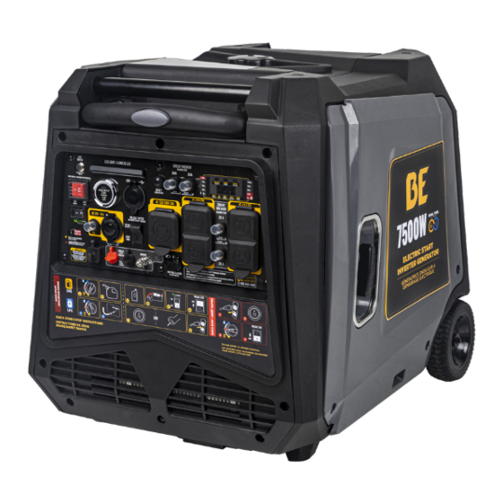
- Page 1 BE7500iD OPERATORS MANUAL OCTOBER 2023...
-
Page 2: Table Of Contents
TABLE OF CONTENTS INTRODUCTION Introduction & Identification Numbers .............. 3 IMPORTANT SAFETY WARNINGS Safety Warnings....................4 SET-UP Component List....................8 Control Panel.....................9 Display Function....................10 Outlet Function....................11 OPERATION Pre-Operation Safety & Inspection Procedures ..........12 Start-Up Procedure ..................13 Shutdown Procedure ..................13 Choosing a Fuel Type ..................14 General Operation.................. -
Page 3: Introduction & Identification Numbers
This manual is considered a part of the machine and needs to be kept in a safe location. If the machine is resold or given to someone else, this manual needs to be included. -
Page 4: Important Safety Warnings Safety Warnings
2. To reduce the risk of injury, close supervision is necessary when a product is used near children. 3. Know how to shut the product off. Be thoroughly familiar with the controls. 4. Stay alert. Watch what you are doing. - Page 5 If the fuel is spilled or the container is not sealed properly, invisible vapors from the fuel can travel along the ground and can be ignited by the appliance’s pilot light or by arcing from electric switches in the appliance.
- Page 6 • Do not enclose the generator or cover it. The generator may become overheated if it is enclosed. If generator has been covered to protect if from the weather during non use, be sure to remove it and keep it well away from the area during generator use.
- Page 7 • Use only “LISTED” extension cords. When a tool or appliance is used outdoors, use only extension cords marked “For Outdoor Use”. Extension cords, when not in use should be stored in a dry and well ventilated area. • Always switch off generator’s AC circuit breaker and disconnect tools or appliances when not in use, before servicing, adjusting, or installing accessories and attachments.
-
Page 8: Component List
COMPONENT LIST 1: Fuel Tank Cap - Provides access to the fuel tank for refueling purposes. 2: Retractable Handle - Allows the user to easily transport the unit. 3: Right Side Outer Cover 4: Control Panel - Allows the user to access the controls for the unit. 5: Engine Vents - Helps move airflow into the unit and regulate engine temperatures. -
Page 9: Control Panel
14: Parallel Connectors: To increase AC power output, the connector sockets are used to connect the two same type generator with special parralel cables. The connector sockets are only used for the communication between 2 units and can not be used for AC power output. Parallel cables are sold seperately. -
Page 10: Display Function
DISPLAY FUNCTION 1: OVERLOAD- A red light indicates the machine is overloaded. 2: OUTPUT- Indicates the inverter is ready to be used. 3: LOW OIL - A red light indicates you do not have enough oil in your machine. 4: POWER OUTPUT - Output power percentage display. -
Page 11: Outlet Function
Output voltage 120V current 20A. 120V (Voltage) X 20A (Current)= 2400W (Output Power) Output voltage can only be 120V and the current can only be 30A. 120V (Voltage) X 30A (Current)= 3600W (Output Power) attention: The total power output of the socket must not exceed the rated power of the generator. -
Page 12: Operation
See the “battery charging” page. LOW TEMPERATURE ENVIRONMENTS: Starting your generator in cold climates (-5ºC (23ºF) to -20ºC (-4ºF)) may be difficult. To help alleviate this issue, you can press the priming pump on the inside of the generator, which will help by forcing fuel into the engines combustion chamber. -
Page 13: Start-Up Procedure
START-UP AND SHUTDOWN PROCEDURE START-UP PROCEDURE CHOOSE YOUR DESIRED FUEL TYPE FILL UNIT WITH OIL OR CONNECT THE CHECK OIL LEVELS AS BATTERY BY NEEDED. ATTACHING THE CLIPS. FOLLOW THE STARTUP STEPS FOR YOUR CHOSEN FUEL TYPE SEE NEXT PAGE FOR GUIDE FLIP THE ECO MODE FLIP THE MAIN PULL THE RECOIL... -
Page 14: Choosing A Fuel Type
CHOOSING A FUEL TYPE GASOLINE START-UP PROCEDURE 1. Switch the fuel source switch to “gasoline” 2. Fill the unit with at least 87 octane gasoline. LIQUID PROPANE START-UP PROCEDURE 1. Connect the LPG hose to your propane tank. 2. Attach the LPG hose to the LPG inlet. 3. - Page 15 • Avoid connecting this generator directly to any commercial power outlet. • When using extension cables, ensure the cable is suited for the load you will be applying to it. Always make sure your extension cable is not damaged.
-
Page 16: General Operation
Ensure AC indicator light is on. Turn your equipment on. tip: before increasing engine speed, eco mode must be off. if you are connecting multiple loads to the generator, connect them from largest to smallest, according to the electrical load. -
Page 17: Battery Charging
Never charge your battery if the temperature is not within 0ºC to 45ºC. Avoid overcharging: • Overcharging lithium-ion batteries should be avoided at all costs. Overcharging a lithium-ion battery will lead to serious degradation of battery performance, damage to the battery itself, or in some cases can... -
Page 18: Maintenance Schedule
25 hours. • If your unit is often used in dusty or harsh environments, the air cleaner should be cleaned every 10 hours. If necessary, the air cleaner should be changed every 25 hours. •... -
Page 19: Spark Plug Replacement
PERFORMING ANY MAINTENANCE. IN ORDER TO PREVENT THE ENGINE FROM STARTING, REMOVE THE SPARK PLUG CAP FROM THE SPARK PLUG. The spark plug is an important part of the generator, which must be inspected regularly. 1. Remove right side cover and spark plug cap from the spark plug. -
Page 20: Oil Service
OIL REPLACEMENT WARNING: DO NOT DRAIN OIL IMMEDIATELY AFTER OPERATING YOUR UNIT. THE OIL WILL BE VERY HOT AND SHOULD BE LEFT TO COOL DOWN IN ORDER TO PREVENT INJURY OR BURNS. 1. Place the generator on a flat surface. -
Page 21: Air Filter
3. Wipe the filter screen dry and place back into tank. 4. Reassemble the fuel tank cap. AIR FILTER CLEANING The air filter can get dirty after prolonged use and needs to be cleaned or replaced regularly. If frequently operating in dusty environments, maintenance must be done more often. -
Page 22: Storage
STORAGE AND TRANSPORT If you are planning to store your generator for longer than 3 months, it is important to follow the necessary storage procedure to prevent damage to the machine. 1. Follow the shutdown procedure to shut down your generator. 2. -
Page 23: Troubleshooting
5. Dirty fuel passageways. 5. Clean out passageways using fuel additive. Heavy deposits may require further cleaning. 6. Carburetor needle stuck. Fuel can be 6. Gentle tap side of carburetor flat chamber smelled in the air. with screwdriver handle. 7. Too much fuel in chamber. - Page 24 TROUBLESHOOTING PROBLEM POSSIBLE CAUSE SOLUTION 1. Spark plug cap is loose. 1. Check cap and wire connections 2. Incorrect spark plug gap or damaged 2. Re-gap or replace spark plug. spark plug. 3. Defective spark plug cap. 3. Replace spark plug cap. engine 4.
- Page 25 TECHNICAL PARAMETERS ITEM BE7500iD Rated Power (Kw) 6.0(GAS) 5.5 (LPG) Max Power (Kw) 7.5(GAS) 6.0(LPG) Engine Model 180F/GL-2 Valve Clearance Input valve: 0.07~0.13 mm, Output valve: 0.10~0.15 mm Stroke X Bore (Mm) 80x62 Engine Type 4-stroke Displacement (Cc) Gas Distribution Mode...
-
Page 26: Circuit Diagram
CIRCUIT DIAGRAM - BE7500iD... -
Page 27: Warranty Statement
DURATION : Electronics will be under warranty for one (1) year from the date of purchase by the original purchaser ( retail customer ). The engine will be under warranty for two (2) years from the date of purchase and can be extended to five (5) years upon registration of the product at: www.bepowerequipment.com/product-registration WHO GIVES THIS WARRANTY (WARRANTOR): BE POWER EQUIPMENT INC. - Page 28 WARRANTY STATEMENT PRODUCT IDENTIFICATION Model Number: Serial Number: Date of Purchase: Dealer Name: NOTES...
- Page 29 NOTES...
- Page 30 NEED HELP? CALL +1 800-663-8331...
Need help?
Do you have a question about the BE7500iD and is the answer not in the manual?
Questions and answers