Arjo Tornado Assembly And Installation Instructions Manual
Hide thumbs
Also See for Tornado:
- Assembly and installation instructions manual (37 pages) ,
- Technical manual (94 pages) ,
- Instructions for use manual (40 pages)
Table of Contents
Advertisement
Quick Links
Advertisement
Table of Contents

Related Manuals for Arjo Tornado


Summary of Contents for Arjo Tornado
- Page 1 ASSEMBLY AND INSTALLATION INSTRUCTIONS Tornado 6001533102_3AU • 2023-12...
- Page 2 Machine model: …………………………………………………… Design Policy and Copyright ® and ™ are trademarks belonging to the Arjo group of companies. © Arjo 2023. As our policy is one of continuous improvement, we reserve the right to modify designs without prior notice. The content of this publication may not be copied either whole or in part without the...
-
Page 3: Table Of Contents
Contents PREFACE ..........................1 SAFETY PRECAUTIONS ....................6 1.1 General safety regulations ...................7 1.2 Isolator switch ......................8 1.3 In an emergency ....................8 1.4 Product liability .....................8 1.5 Attention symbols ....................8 2 INSTALLATION OF MACHINE ...................9 2.1 General ........................9 2.1.1 Make sure assembly and installation work is carried out .....9 2.1.2 Installation order ...................9 2.1.3 Installation alternatives .................9 2.2 Unpacking ......................10... - Page 4 5 TECHNICAL DATA .....................27 5.1 Connections .......................27 5.2 Environmental requirements ................27 5.3 Water consumption ....................27 5.4 Exterior dimensions ...................27 5.5 Weight ........................27 5.6 Protection class ....................28 5.7 Sound level ......................28 5.7.1 Estimated sound level .................28 5.7.2 Example ....................29 6 WATER QUALITY ......................30 6.1 Requirements ....................30 6.2 Main factors .......................30 6.3 Recommendation ....................30...
-
Page 5: Preface
Users must read through the manual before using the machine for the first time, as well as familiarizing themselves with the operation of the machine and its safety instructions. Operators and maintenance personnel must have completed training through the marketing organization of Arjo. The information in this manual describes the machine as dispatched from Arjo. There may be differences due to customization for customers or countries. The machine is accompanied by the following documentation: •... -
Page 6: Safety Precautions
1 SAFETY PRECAUTIONS Operators and maintenance personnel must undergo safety training for the machine. All personnel who handle chemicals for washing and disinfection must understand the washing process, possible health hazards and ways of detecting leaks of toxic chemicals. Operators and maintenance personnel must undergo regular training in the operation and maintenance of the equipment. There must be a documented list of personnel who have been trained to use the machine. -
Page 7: General Safety Regulations
Before starting, check the waste outlet at the bottom of the flushing chamber for blockages. This will ensure that the machine works properly. • Do not place items that are sensitive to heat or moisture on top of the flusher-disinfector. • Spare parts must only be obtained from Arjo’s sales companies. -
Page 8: Isolator Switch
Close shutoff valves in the water and any steam supply lines. 1.4 Product liability CE marking indicating conformity with European Community harmonised legislation. Any modification or incorrect use of the equipment without the approval of Arjo negates Arjo’s product liability. CE marking indicating conformity with European Community harmonised legislation Figures indicate Notified Body supervision. 1.5 Attention symbols There are warnings, instructions, and advice in this manual that require extra attention. -
Page 9: Installation Of Machine
2 INSTALLATION OF MACHINE 2.1 General 2.1.1 Make sure assembly and installation work is carried out WARNING! To avoid the risk of back injury, this equipment should be assembled and installed by at least two people. • by qualified personnel. • in accordance with current local regulations and rules. •... -
Page 10: Unpacking
2.2 Unpacking Note! Before installing make sure the flusher-disinfector has not been damaged in transit. The following items must accompany the flusher-disinfector when it is delivered: • Two cabinet keys • One folder containing documentation The flusher-disinfector is supplied securely bolted to a pallet. Remove the packaging. Move the flusher- disinfector as close to the installation position as possible, when still secure to the pallet using mechanical means. -
Page 11: Scale Drawings
2.3 Scale drawings 2.3.1 Freestanding model placed next to wall Scale drawings apply to the FD1800 and FD1810 models. Figure 2. Scale drawing Hot Water Waste connection, S, floor Cold Water Transformer Waste connection, P, Extension frame wall (option) Transformer: •... -
Page 12: Freestanding Model Wall-Mounted
2.3.2 Freestanding model wall-mounted Scale drawings apply to the FD1800 and FD1810 models. 84,5 Figure 3. Scale drawing Hot Water Wall bracket Cold Water Transformer Waste connection, P, wall Transformer: • Dimensions: 300x200x210. • Positioning: The transformer can be moved, see “Connecting electrical power”. -
Page 13: Under-Bench Model
2.3.3 Under-bench model Scale drawings apply to the FD1805 model. Figure 4. Scale drawing Hot Water Protection sheet* (option) Cold Water Without worktop Waste connection, P, wall Connections to optional worktop** Waste connection, S, floor * Protection sheet must be used if the machine is installed under a bench or similar. -
Page 14: Assembly
2.4 Assembly 2.4.1 Freestanding model placed next to wall Install the machine as follows: Measure out and drill the holes for the wall bracket (anti- tipper) used to secure the machine to the wall. Install the water trap to the waste outlet: •... -
Page 15: Freestanding Model Wall-Mounted
2.4.2 Freestanding model wall-mounted Install the machine as follows: Drill the holes for the wall bracket in accordance with the hole pattern. Drill the hole for attachment in the bottom frame. Fix the wall bracket (A) to the wall (B) with screws. Figure 5. -
Page 16: Under-Bench Model
2.4.3 Under-bench model Install the machine as follows: Install the water trap to the waste outlet: • The trap can be connected towards the rear (P-trap) or downwards (S-trap). • The pipe diameter is 90 or 110 mm and should be able to handle 1 liter per second. -
Page 17: Sealing Requirements For Under-Bench Model
2.4.5 Sealing requirements for under-bench model The following applies to the under-bench model FD1805. If the outside of the machine is in contact with surrounding surfaces, the machine must be waterproofed against these surfaces to prevent water from leaking into the machine. This applies to the machine’s top side (A), side panels (B) and back side (C). -
Page 18: Requirements For Kiwa Certified Installations
2.5.2 Requirements for KIWA certified installations Use KIWA approved check valves from Arjo (A) between the water connections (B) and the machine water hoses (C). Figure 9. Installation of check valves 2.5.3 Requirements for backflow prevention installations Backflow prevention devices are to be added during bath installation. The backflow prevention device is a Dual Check Valve – part number RMC7186.2 which is made of chrome and is Australian Watermarked. -
Page 19: Electrical Connections
2.6 Electrical connections 2.6.1 Positioning the transformer Placement alternatives: • The transformer for freestanding models can be moved: ͦ to the opposite side of the machine if so required due to water connections. Ensure that the transformer does not encroach on the area intended for detergents. ͦ... -
Page 20: Coupling Alternative
2.6.3 Coupling alternative 2.6.3.1 Connection diagram 3N+PE 1N+PE -X50 -X50 Figure 11. Electrical connection 3+PE 2+PE -X50 -X50 Figure 12. Electrical connection 2.6.3.2 FD1800/FD1810 Voltage Connection Frequency Fuse Power requirement 415 V 3N+PE 50 Hz 3 × 10 A 3.75 kW 400 V 3N+PE 60 Hz... - Page 21 2.6.3.3 FD1805 Voltage Connection Frequency Fuse Power requirement 400 V 3N+PE 60 Hz 3 × 10 A 3.75 kW 400 V 3N+PE 50 Hz 3 × 10 A 3.75 kW 380 V 3N+PE 60 Hz 3 × 10 A 3.75 kW 380 V 3N+PE 50 Hz 3 ×...
-
Page 22: Installation Of Options
3 INSTALLATION OF OPTIONS 3.1 Printer (FD1800/1810) 3.1.1 Connection 1. Switch off the power to the machine. 2. Take the top panel off the machine. Figure 13. Placement of the opening in the top panel Make an opening in the top panel (A) for the printer cable. • Use a file or some other suitable tool. • Make an opening within the area (B), which applies to both the left and right side of the top panel. -
Page 23: Configuration
Connect the printer cable: • Connect one end to the interface cable (E). • Attach the cable bracket (6001003001) to the metal under the opening in the top panel (F), and attach the printer cable. Replace the top panel. Position the printer (G) in a suitable position, connect the power to the printer, and turn it on. -
Page 24: Inspecting The Installation
4 INSPECTING THE INSTALLATION 4.1 When the work is complete, check that • all parts have been installed according to the installation manual. • all screws have been properly tightened. • there are no sharp edges on any parts that may come into contact with people. -
Page 25: Function Check
4.2 Function check WARNING! Conduct a ground continuity test before the function check and document the result. • Check that the flusher-disinfector is connected to the correct supply voltage and that it is protected by a fuse of the correct rating as shown on the type plate. • Open the water valves and close the isolator switch. -
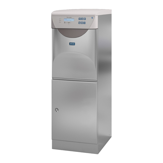
Page 26: Control Panel
4.3 Control panel 4.3.1 FD1800/FD1805 Figure 15. Control panel Red: Error indication Economy program Green: Process Detergent* complete Normal program Yellow: Process Intensive program running Display 5. Rim flushing * Option 4.3.2 FD1810 Figure 16. Control panel Red: Error indication Economy program Green: Process Detergent* complete... -
Page 27: Technical Data
5 TECHNICAL DATA 5.1 Connections Connection Connection Flow requirements requirements Cold water (CW) 15 mm (G½") 100 – 800 kPa 20 l/min (1 – 8bar) Hot water (HW) 15 mm (G½") 100 – 800 kPa 20 l/min (1 – 8bar) Drain (D) Ø 90 mm or Ø 110 mm Top 1 l/sec 5.2 Environmental requirements Room temperature... -
Page 28: Protection Class
5.6 Protection class FD1800, FD1810 FD1805 Pollution Degree Overvoltage category Protection class IP22 (standard) IP21 IP24 (option) Max altitude* 2000m above sea level 2000m above sea level * Maximum height above sea level to use the machine. 5.7 Sound level 5.7.1 Estimated sound level Calculated sound power level L for the test object, dB ref 1 pW, is... -
Page 29: Example
5.7.2 Example The calculated sound power level implies different sound levels L in different types of space. With larger room volumes, the sound level decreases slightly and with smaller room volumes it increases slightly. The table below shows examples of what sound level to expect in practice. The room types used in the example are: • Hard sound: All surfaces of tile, plaster, concrete or similar, i.e. -
Page 30: Water Quality
Sanitary chemicals: High concentrations of, and high exposure to, sanitary chemicals may cause corrosion and pitting on stainless steel. 6.3 Recommendation • Arjo recommends that water used in the pre-rinsing, washing and final rinsing phases should be of drinking quality in accordance with the guidelines. • Recommended water quality is drinking water with max 5°dH. -
Page 31: Local Standard, Typical Specification
6.5 Local standard, typical specification A typical specification for treated water is: 5.5 to 8 Conductivity <30 µs.cm-1 <40 mg/l Maximum hardness <50 mg/l Chlorine <10 mg/l Heavy metals <10 mg/l Phosphates <0.2 mg/l as P2O5 Silicates <0.2 mg/l as SiO2 Endotoxins <0.25 EU/ml Total number of micro- <100 per 100 ml organisms... -
Page 32: End Of Life Disposal
7 END OF LIFE DISPOSAL Equipment that has electrical and electronic components should be disassembled and recycled per Waste of Electrical and Electronic Equipment (WEEE) or in accordance with local or national regulation. Disinfection liquids – if you have extra liquid, it’s safe to pour it down the drain with running water. - Page 33 Intentionally left blank...
- Page 34 Intentionally left blank...
- Page 35 AUSTRALIA FRANCE POLSKA Arjo Australia Arjo SAS Arjo Polska Sp. z o.o. Building B, Level 3 2 Avenue Alcide de Gasperi ul. Ks Piotra Wawrzyniaka 2 11 Talavera Road CS 70133 PL-62-052 KOMORNIKI (Poznań) Macquarie Park, NSW, 2113, FR-59436 RONCQ CEDEX...
- Page 36 At Arjo, we believe that empowering movement within healthcare environments is essential to quality care. Our products and solutions are designed to promote a safe and dignified experience through patient handling, medical beds, personal hygiene, disinfection, diagnostics, and the prevention of pressure injuries and venous thromboembolism. With over 6500 people worldwide and 65 years caring for patients and healthcare professionals, we are committed to driving healthier outcomes for people facing mobility challenges.
Need help?
Do you have a question about the Tornado and is the answer not in the manual?
Questions and answers