
Related Manuals for Schmalz VSi HD


Summary of Contents for Schmalz VSi HD
- Page 1 Operating instructions Vacuum Switch VSi HD WWW.SCHMALZ.COM EN-US · 30.30.01.03279 · 01 · 12/22...
- Page 2 Published by © J. Schmalz GmbH, 12/22 This document is protected by copyright. J. Schmalz GmbH retains the rights established thereby. Repro- duction of the contents, in full or in part, is only permitted within the limits of the legal provisions of copyright law. Any modifications to or abridgments of the document are prohibited without explicit writ- ten agreement from J. Schmalz GmbH.
-
Page 3: Table Of Contents
Modifications to the Product ...................... 8 3 Product description............................ 9 General Description .......................... 9 Versions .............................. 9 Design of the VSi HD ........................... 9 LED Status Display.......................... 10 4 Technical Data............................... 11 General Data ............................ 11 Electrical Data ............................ 11 Mechanical Data .......................... - Page 4 Materials Used ........................... 30 14 Accessories .............................. 31 15 Declarations of Conformity.......................... 32 15.1 EU Declaration of Conformity...................... 32 15.2 UKCA Conformity .......................... 33 16 VSi HD Data Dictionary 21.10.01.00121_01 2022-04-20.pdf .............. 34 4 / 36 EN-US · 30.30.01.03279 · 01 · 12/22...
-
Page 5: Important Information
ð Failure to follow the instructions in these Operating instructions may result in injuries! ð Schmalz is not liable for damage or malfunctions that result from failure to heed these instructions. If you still have questions after reading the technical documentation, contact Schmalz Service at: www.schmalz.com/services... -
Page 6: Symbols
1 Important Information 1.4 Symbols This symbol indicates useful and important information. ü This symbol represents a prerequisite that must be met prior to an operational step. 4 This symbol represents an action to be performed. ð This symbol represents the result of an action. Actions that consist of more than one step are numbered: 1. -
Page 7: Fundamental Safety Instructions
2 Fundamental Safety Instructions 2.1 Intended use The vacuum switch VSi HD is to be used only for measuring vacuum. For further information, see the tech- nical data. Any other use is considered improper by the manufacturer and is deemed as contrary to the designated use. -
Page 8: Residual Risks
2.6 Modifications to the Product Schmalz assumes no liability for consequences of modifications over which it has no control: 1. The product must be operated only in its original condition as delivered. 2. Use only original spare parts from Schmalz. -
Page 9: Product Description
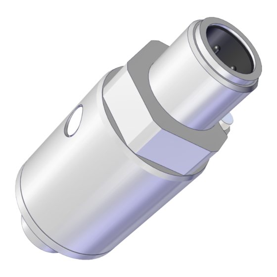
Electrical connection VSi HD V (-1 to 0 bar) with LED M12-4 (1xM12, 4-pole) 3.3 Design of the VSi HD Fluid connector M12-4 electrical connection (plug) Membrane (pressure balancing for sensor) Light-emitting diode (LED) status display EN-US · 30.30.01.03279 · 01 · 12/22... -
Page 10: Led Status Display
3 Product description 3.4 LED Status Display The VSi HD has a light-emitting diode (LED) (4) for dis- playing status information. The table below describes the possible states on the LED displays. LED color Behavior Status — None No power supply Green Continuous Operating voltage indicator light... -
Page 11: Technical Data
4 Technical Data 4 Technical Data 4.1 General Data Operating pressure range -1 to 0 bar Accuracy ± 3% FS Resolution 1 mbar Degree of protection IP 65 (M8/M12 plugged in) Working temperature 0 to 50° C Storage temperature –10 to 60° C Permitted humidity 10 to 90% RH (free from condensation) Overpressure resistance 8 bar Measuring medium... -
Page 12: Factory Settings
4 Technical Data All dimensions given in millimeters [mm]. 4.4 Factory Settings Parameter 10.06.02.00760 Switching point 1 Switching point mode and logic Normally open two-point mode (H.no) Vacuum level switching point SP1 550 mbar Vacuum level reset point rP1 500 mbar Window hysteresis Hy1/leakage limit per sec L-1 20 mbar Switch-on delay dS1, 0 ms... -
Page 13: Installation
5 Installation 5 Installation 5.1 Mounting NOTE Exceeding the specified maximum tightening torques during mounting Product damage 4 Ensure that the specified maximum tightening torques are complied with. Position Description Tightening torques Fluid connector 2.5 Nm Electrical connection (union nut) 0.8 Nm Electrical connection (plug) (>... - Page 14 Symbol Function Brown Supply voltage White OUT2 Signal output 2 (SIO) Blue Weight Black OUT1 C/Q (IO-Link) and signal output 1 (SIO) When using a Schmalz connection cable (see “Accessories”) 14 / 36 EN-US · 30.30.01.03279 · 01 · 12/22...
-
Page 15: Io-Link Commissioning
(e.g. Siemens PCT, Beckhoff TwinCAT etc.). The necessary device description data (IODD) for the switch can be downloaded from our website www.schmalz.com. The second output OUT2 for the vacuum switch is deactivated in IO-Link operation. -
Page 16: Interfaces
The measured value is displayed as 14-bit unsigned vacuum in millibar (vacuum positive): A detailed description of all the device parameters can be found in the data dictionary, which can be downloaded together with the IODD as a ZIP archive from www.schmalz.com. 16 / 36... -
Page 17: Replacement Of The Device With A Parameterization Server
7 Interfaces 7.3 Replacement of the Device with a Parameterization Server The IO-Link protocol provides an automated process for transferring data when a device is replaced. For this Data storage mechanism, the IO-Link master mirrors all setting parameters for the device in a sepa- rate non-volatile memory. -
Page 18: Description Of Functions
8 Description of Functions 8 Description of Functions 8.1 Overview of Functions Description Parame- See section Switching point setting SP1/FH1 Switching Points rP1/FL1 hy1/L-1 SP2/FH2 rP2/FL2 hy2/L-2 Switching point mode and logic (> See ch. 8.4.1 Switching Point Mode and Switching Point Logic, p. Teach-in Teach-in for Switching Points Switch-on and switch-off delay... -
Page 19: Measuring Vacuum
8 Description of Functions 8.2 Measuring Vacuum The VSi-HD series switch measures the vacuum relative to the ambient air pressure. • Vacuum switch VSi-HD: The vacuum will be indicated as positive pressure difference. If there is excessive overpressure, an event is sent via IO-Link indicating that the measured value is outside of the valid range. - Page 20 8 Description of Functions 8.4.2 Two-Point Mode The two-point mode is a threshold switch with hysteresis. When the measurement value increases, the switching point will be active when the switch-on threshold SPx is reached and remains on until it falls below the reset threshold rPx. The following must always apply for switching thresholds and reset thresholds: |SPx| >...
-
Page 21: Teach-In For Switching Points
8 Description of Functions 8.4.4 Condition Monitoring Mode (Leakage Measurement) The condition monitoring switching point mode is used to monitor the quality of a vacuum suction sys- tem. (A requirement for this is that the suction system that is pneumatically connected to the switch has an air saving function or vacuum control in accordance with the two-point principle.) In this case, the vac- uum switch can measure the vacuum leakage in millibars per second between two drainage cycles. -
Page 22: Additional Switching Point Settings
8 Description of Functions 8.6 Additional Switching Point Settings 8.6.1 Switch-on and Switch-off Delay For each switching point and each associated limit value, a delay time can be set, with the exception of condition monitoring mode. Here, this parameter can only be defined for the switching point SP1. In Con- dition monitoring mode, the parameters dSx and drx are also not shown on the display. -
Page 23: Device Identification
8 Description of Functions 8.7.2 IO-Link Device Access Locks In IO-Link mode, the “Device access locks” default parameter is available to prevent changes to parameter values using the user menu or IO-Link. You can also prevent the use of the Data storage mechanism de- scribed in IO-Link Standard V1.1. -
Page 24: System Monitoring And Diagnostics
8 Description of Functions 8.9 System Monitoring and Diagnostics 8.9.1 Minimum and Maximum Values The maximum and minimum vacuum and operating voltage values that were measured since the last switch-on are logged by the switch and can be queried. The maximum and minimum values can be reset via IO-Link during operation using the appropriate sys- tem commands. -
Page 25: Zero-Point Adjustment (Calibration)
8 Description of Functions 8.10 System Commands 8.10.1 Reset to Factory Settings WARNING By activating/deactivating the product, output signals lead to an action in the pro- duction process! Personal injury 4 Avoid possible danger zone. 4 Remain vigilant. All the setting parameters for the product are reset to factory settings using this function. The function for resetting factory settings does not affect the following elements: •... -
Page 26: Help With Malfunctions
9 Help with Malfunctions 9 Help with Malfunctions Fault Cause Measure 4 Connection to IO-Link class A port Master or peripheral Connection to IO-Link master with power supply disturbed IO-Link class-B port 4 Check electrical connection and pin No output signal Incorrect electrical connection assignment 4 Adapt the transistor function (PNP/... -
Page 27: List Of Error Numbers
10 List of Error Numbers 10 List of Error Numbers When a known error occurs, this is reported in the form of an error number. Additional descriptions of errors and system statuses are available via IO-Link (> See ch. 8.9.3 Status Sig- nals, p. -
Page 28: Cleaning The Product
11 Cleaning the Product 11 Cleaning the Product 1. For cleaning, do not use aggressive cleaning agents such as industrial alcohol, white spirit or thin- ners. Only use cleaning agents with a pH between 7 and 12. 2. Remove dirt on the exterior of the device with a soft cloth and soap suds at a maximum tempera- ture of 60° C. -
Page 29: Warranty
A warranty claim can only be accepted by Schmalz if the product has been installed and used in accor- dance with its corresponding operating and assembly instructions. In the case of inappropriate handling or use of force, any warranty and liability claims shall be void. -
Page 30: Decommissioning And Recycling
13 Decommissioning and Recycling 13 Decommissioning and Recycling 13.1 Disposing of the Product 1. Dispose of the product properly after replacement or decommissioning. 2. Observe the country-specific guidelines and legal obligations for waste prevention and disposal. 13.2 Materials Used Component Material Housing Anodized aluminum (natural) Fluid connection Anodized aluminum (natural) Seals... -
Page 31: Accessories
14 Accessories 14 Accessories Type Designation Description Part no. Mounting kit BEF-WIN 21x34.5x59 1.5 Metal bracket for simple switch 10.06.02.00061 attachment; incl. 1/8" nut Connection cable ASK B-M12-4 2000 S-M12-4 M12-4 female connector with 21.04.05.00087 M12-4 plug Connection cable ASK B-M12-4 5000 PUR GE M12-4 female connector, cable 21.04.05.00263 end open... -
Page 32: Declarations Of Conformity
15 Declarations of Conformity 15 Declarations of Conformity 15.1 EU Declaration of Conformity The manufacturer Schmalz confirms that the product VSi HD described in these operating instructions ful- fills the following applicable EU directives: 2014/30/EU Electromagnetic Compatibility 2011/65/EU Directive on the restriction of the use of certain hazardous substances in... -
Page 33: Ukca Conformity
15 Declarations of Conformity 15.2 UKCA Conformity The manufacturer Schmalz confirms that the product described in these operating instructions fulfills the following applicable UK regulations: 2016 Electromagnetic Compatibility Regulations 2012 The Restriction of the Use of Certain Hazardous Substances in Electrical and... - Page 34 IO-Link Data Dictionary VSi HD series 21.10.01.00176/00 21.04.2022 J. Schmalz GmbH Johannes-Schmalz-Str. 1, D 72293 Glatten Tel.: +49(0)7443/2403-0 www.schmalz.com info@schmalz.de IO-Link Implementation Vendor ID 234 (0x00EA) Device ID 100616 (0x018908) SIO-Mode IO-Link Revision IO-Link Profile Smart Sensor Profile with 2 Binary Data Channels, 1 Process Data Variable, Teach-In and Diagnosis IO-Link Bitrate 38.4 kBit/sec (COM2)
- Page 35 IO-Link Data Dictionary VSi HD series 21.10.01.00176/00 21.04.2022 J. Schmalz GmbH Johannes-Schmalz-Str. 1, D 72293 Glatten Tel.: +49(0)7443/2403-0 www.schmalz.com info@schmalz.de 0x0040 Sensor Value LO 2 bytes Lowest measured sensor value since power-up 0x0040 Sensor Value HI 2 bytes Highest measured sensor value since power-up...
- Page 36 At Your Service Worldwide Vacuum automation Handling systems WWW.SCHMALZ.COM/AUTOMATION WWW.SCHMALZ.COM/EN-US/VACUUM-LIFTERS- AND-CRANE-SYSTEMS J. Schmalz GmbH Johannes-Schmalz-Str. 1 72293 Glatten, Germany T: +49 (0) 7443 2403-0 schmalz@schmalz.de WWW.SCHMALZ.COM...
Need help?
Do you have a question about the VSi HD and is the answer not in the manual?
Questions and answers