Schmalz VS-V-W-D PNP K 3C-D Operating Instructions Manual
Vacuum/pressure switch
Hide thumbs
Also See for VS-V-W-D PNP K 3C-D:
- Short instruction manual (45 pages) ,
- Short instruction manual (41 pages)

Related Manuals for Schmalz VS-V-W-D PNP K 3C-D


Summary of Contents for Schmalz VS-V-W-D PNP K 3C-D
-
Page 1: Operating Instructions
Vacuum/pressure switch VS-V/P-W-D K 3C-D Operating Instructions WWW.SCHMALZ.COM EN-US · 30.30.01.01858 · 00 · 04/19... - Page 2 Published by © J. Schmalz GmbH, 04/19 This document is protected by copyright. J. Schmalz GmbH retains the rights established thereby. Repro- duction of the contents, in full or in part, is only permitted within the limits of the legal provisions of copyright law. Any modifications to or abridgments of the document are prohibited without explicit writ- ten agreement from J. Schmalz GmbH.
-
Page 3: Table Of Contents
1 Important information ........................... 5 1.1 Note on Using this Document ....................... 5 1.2 The technical documentation is part of the product ................ 5 1.3 Warnings in this document........................ 5 1.4 Symbol.............................. 5 2 Fundamental Safety Instructions........................ 6 2.1 Intended use ............................ 6 2.2 Non-Intended Use .......................... - Page 4 9 EC Declaration of Conformity ........................ 24 4 / 26 EN-US · 30.30.01.01858 · 00 · 04/19...
-
Page 5: Important Information
ð Failure to follow the instructions in this operating instructions may result in life-threatening injuries! ð Schmalz is not liable for damage or malfunctions that result from failure to heed these instructions. If you still have questions after reading the technical documentation, contact Schmalz-service at: www.schmalz.com/services... -
Page 6: Fundamental Safety Instructions
Intended use includes the observance of the technical data and the installation and operating instructions in this manual. 2.2 Non-Intended Use Schmalz accepts no liability for damages caused by the use of the Vacuum/pressure switch for purposes other than those described under "Intended Use." Non-intended use includes the following: •... -
Page 7: Product Description
PNP: 2 PNP output / 1 PNP output + Analog output (1 – 5 V) Part no. Type key Pressure range Outputs 10.06.02.00678 VS-V-W-D PNP K 3C-D Vacuum (0.1 to 1.03 bar) 2 PNP 10.06.02.00679 VS-V-W-D NPN K 3C-D Vacuum (0.1 to 1.03 bar) 2 NPN 10.06.02.00680... -
Page 8: Display And Operating Element In Detail
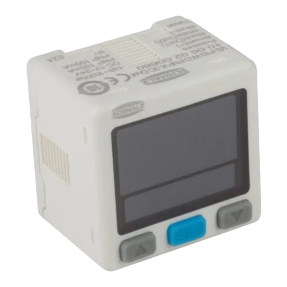
Product description 3.3 Display and Operating Element in Detail The Vacuum/pressure switch display and operating element features 3 buttons and two display areas. Display for output 1 Display for output 2 Lock indicator Unit for pressure display Main display area, two-colored Setting mode of lower display area DOWN BUTTON SET BUTTON... -
Page 9: Technical Data
Technical Data 4 Technical Data 4.1 General Parameters Parameter Unit Value for VS-V... Value for VS-P10... Value for VS-VP1... Measuring medium — Non-aggressive, flammable gases; dry, oil-free air Measurement range -1.03 to 0.00 -1.0 to 10.0 -1.0 to 1.0 Adjustable range -1.03 to 0.10 -1.03 to 10.3 -1.03 to 1.03 Max. -
Page 10: Dimensions
Technical Data Parameter Unit Value for VS-V... Value for VS-P10... Value for VS-VP1... Vibration — Total amplitude 1.5 mm, 10 Hz ~ 150 Hz ~ 10 Hz for 1 minute, two hours in each direction X, Y and Z Shock strength —... -
Page 11: Installation
Installation 5 Installation 5.1 Mounting The sensor may be installed in any position. To ensure correct function and to prevent faults in the sensor, observe the following installation instruc- tions: Do not drop the Vacuum/pressure switch, and do not subject it to excessive impacts. Even if the switch housing is undamaged, internal components may be damaged, resulting in malfunction. - Page 12 Installation NOTE Connect with the power turned on Damage to the electronics and/or malfunction 4 Switch off the power supply before connecting cables! The vacuum switch is supplied with a 4-wire connection cable with open cable ends. Integrate the Vacuum/pressure switch into your application in accordance with the electrical circuit dia- gram.
-
Page 13: Operation
Operation 6 Operation 6.1 Safety Instructions NOTE Operating pressure above the recommended maximum pressure Damage to the switch 4 Only use the Vacuum/pressure switch within the nominal pressure range. Do not drop the vacuum switch or subject it to impacts. Even if the housing is undamaged, internal components may be damaged and cause malfunction. 6.2 Setting Up the Basic Functions The Vacuum/pressure switch is operated using three buttons: SET BUTTON... -
Page 14: Functions In The Additional Functions Menu
Operation Parameter Display code Display code Explanation for the lower for the main display display This selection will not be dis- Hysteresis mode played if only one output is avail- Window Comparator mode able. OUT2 output "normally open" NO mode Switching logic "normally open"... -
Page 15: Energy-Saving Function
Operation The following table shows an overview of the display codes and parameters in the Additional Functions menu: Parameter Display code for Display code for Explanation the lower display the main display -> 4, ... ,8, Hysteresis value Fixed hysteresis setting 1, 2 Display color Select the display color for output... -
Page 16: Setting The Vacuum Or Pressure Unit
Operation 1. Press the button until "00" is dis- played. ð CLr is indicated in the lower display. 2. Release the buttons. ð The Vacuum/pressure switch is set to zero. 6.7 Setting the Vacuum or Pressure Unit The physical unit that is used to display the measured values as well as the limit values a nd hystereses on the main display can be set via the main menu under the menu item [ uni ]: Unit Display code, setting parameters... -
Page 17: Setting The Switching Points For Two Outputs
Operation 6.8.2 Setting the Switching Points for Two Outputs Setting condition 1: • OUT1 mode = "op5" (One point set mode) • OUT2 mode = "off" (not used) ü Measurement mode, P-1 and the currently set value are displayed alternately. 4 P-1 Enter the switching point value with the button. -
Page 18: Locking The Keypad
Operation button to change to switching point X-1. 2. Use the 3. X-1 Enter the switching point value with the button. button to change to switching point P-2. 4. Use the 5. P-2 Enter the switching point value with the button. -
Page 19: Fine Adjustment Of The Display Values
Operation ü The Vacuum/pressure switch is in Measurement mode. 4 Press the button for at least two seconds. ð PE- is indicated in the main display ð and bo- is indicated in the lower display. ð The display changes and alternates between the measured values of the maximum and minimum measurements and the display codes. -
Page 20: Switching Logic
Operation 6.12 Switching Logic NO mode NC mode One point set mode Positive Vacuum Positive/Compound Vacuum (VS-P10) (VS-V) (VS-P10) (VS-V) P-1 Vacuum P-1 Positive P-1 Positive P-1 Vacuum P-2 * P-2 * P-2 * P-2 * Hysteresis mode Positive/Compound Vacuum Positive/Compound Vacuum (VS-P10) (VS-V) -
Page 21: Troubleshooting
Troubleshooting 7 Troubleshooting Error type Error Error description Troubleshooting code Over- OUT1 The load current at output 1 1. Turn off the power and determine load is more than 100 mA the cause of the overload current, current or lower the load to less than 100 OUT2 The load current at output 2 is more than 100 mA... -
Page 22: Accessories
Accessories 8 Accessories 8.1 Accessory Items Description Part no. Horizontal mounting bracket; BEF-WIN 20x43.5x29.5 1.5 10.06.02.00685 Front mounting bracket; BEF-WIN 30x43.5x29.5 1.5 10.06.02.00686 Mounting frame for mounting into switch panel; EINB-RAx8.5x30 VS, instal- 10.06.02.00427 lation kit, 3-piece, with protective glass Connection plug (ready to assemble); ASS S-M12-5 SK 21.04.05.00251 8.2 Mounting Accessories When ordering the holders, the two fastening screws required (M3*0.5P) are included in the delivery:... - Page 23 Accessories Holder 10.06.02.00686 Mounting Dimensions Adapter for mounting into switch panel 10.06.02.00427 Mounting Dimensions EN-US · 30.30.01.01858 · 00 · 04/19 23 / 26...
- Page 24 EC Declaration of Conformity 9 EC Declaration of Conformity EC Declaration of Conformity The manufacturer Schmalz confirms that the Vacuum/pressure switch described in these operating instruc- tions fulfill the following applicable EC directives: 2014/30/EU Electromagnetic Compatibility 2011/65/EU Directive on the restriction of the use of certain hazardous substances in...
- Page 25 30.30.01.01858 · 00 · 04/19 25 / 26...
Need help?
Do you have a question about the VS-V-W-D PNP K 3C-D and is the answer not in the manual?
Questions and answers