
Related Manuals for Schmalz VSi Series


Summary of Contents for Schmalz VSi Series
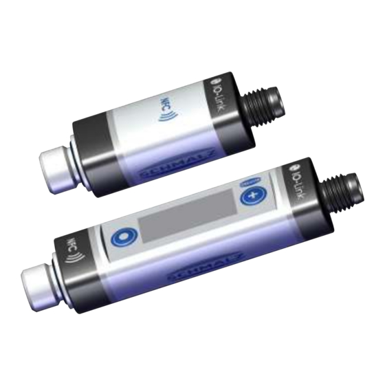
- Page 1 Vacuum/Pressure Switch VSi / VSi-...-D Operating instructions WWW.SCHMALZ.COM EN-US · 30.30.01.00956 · 03 · 05/22...
- Page 2 Published by © J. Schmalz GmbH, 05/22 This document is protected by copyright. J. Schmalz GmbH retains the rights established thereby. Repro- duction of the contents, in full or in part, is only permitted within the limits of the legal provisions of copyright law. Any modifications to or abridgments of the document are prohibited without explicit writ- ten agreement from J. Schmalz GmbH.
-
Page 3: Table Of Contents
Contents Contents 1 Important Information ........................... 5 Note on Using this Document ...................... 5 The technical documentation is part of the product ................ 5 Symbol.............................. 5 2 Fundamental Safety Instructions........................ 6 Intended use ............................ 6 Non-Intended Use .......................... 6 Personnel Qualification........................ 6 Warnings in This Document........................ - Page 4 Contents 9 Description of Functions.......................... 25 Overview of Functions ........................ 25 Measurement of Pressure and/or Vacuum.................. 26 Monitoring the Operating Voltage.................... 26 Switching Points .......................... 26 Teach-in for Switching Points ...................... 29 Additional Switching Point Settings .................... 30 Display Screen............................ 31 Access Rights............................
-
Page 5: Important Information
ð Failure to follow the instructions in these Operating instructions may result in injuries! ð Schmalz is not liable for damage or malfunctions that result from failure to heed these instructions. If you still have questions after reading the technical documentation, contact Schmalz Service at: www.schmalz.com/services... -
Page 6: Fundamental Safety Instructions
Intended use includes observing the technical data and the installation and operating instructions in this manual. 2.2 Non-Intended Use Schmalz accepts no liability for damages caused by the use of the product for purposes other than those described under "Intended Use." Non-intended use includes the following: •... -
Page 7: Residual Risks
2.6 Modifications to the Product Schmalz assumes no liability for consequences of modifications over which it has no control: 1. The product must be operated only in its original condition as delivered. 2. Use only original spare parts from Schmalz. -
Page 8: Product Description
Product description 3 Product description 3.1 General Description The vacuum switch and pressure switch versions belonging to the VSi series are referred to only as the switch below. The VSi-series switch can be operated in two operating modes. • Via direct connection to discrete inputs (standard I/O = SIO) or •... -
Page 9: Design Of Vsi
Product description 3.4 Design of VSi ... D (with Display) Fluid connector MODE button Switching point 1 display, ORANGE or op- Display erating voltage display, GREEN Position of the NFC antenna behind the SET button display Electrical connection M12-4 or M8-4 Switching point 2 display, ORANGE EN-US ·... -
Page 10: Technical Data
Technical Data 4 Technical Data 4.1 General Data Property Version V Version P10 Version VP8 Operating pressure -1 to 0 bar 0 to 10 bar -1 to 8 bar range Overpressure resistance 8 bar 15 bar 12 bar Solution 1 mbar 11 mbar Vacuum 2 mbar/pres- sure 11 mbar Degree of protection IP 65 (M8/M12 plugged in) Working temperature 0 to 50° C... -
Page 11: Mechanical Data
Technical Data 4.3 Mechanical Data VSi-...-D Type VSi ... M8-4 38.0 55.0 M8x1 male thread G1/8" male M5 female 19.6 VSi ... M12-4 38.0 56.0 M12x1 thread thread male thread VSi ... D M8-4 60.5 77.5 M8x1 male thread VSi ... D M12-4 60.5 78.5 M12x1... -
Page 12: Factory Settings
Technical Data 4.4 Factory Settings Parameter VSi-V VSi-P10 VSi-VP8 VSi-V-SA Switching point 1 Switching point mode and Normally open two-point mode (H.no) logic Switching point SP1 750 mbar 5500 mbar –750 mbar –750 mbar Reset point rP1 600 mbar 5000 mbar –600 mbar –600 mbar Window hysteresis Hy1/leakage 20 mbar 100 mbar 20 mbar 20 mbar... -
Page 13: Installation
Installation 5 Installation 5.1 Mounting NOTE Exceeding the specified maximum tightening torques during mounting Product damage 4 Ensure that the specified maximum tightening torques are complied with. VSi ... D Position Description Max. tightening torque Fluid connector 2.5 Nm Electrical connection (plug) See note Electrical connection (union nut) 0.8 Nm Screw-in aid (see accessories) - Page 14 White Signal output 2 (SIO) or analog output Blue Ground OUT1 Black C/Q (IO-Link) and signal output 1 (SIO) When using a Schmalz connection cable (see “Accessories”) For version VSi-V-SA 14 / 44 EN-US · 30.30.01.00956 · 03 · 05/22...
-
Page 15: Io-Link Commissioning
(e.g. Siemens PCT, Beckhoff TwinCAT etc.). The necessary device description data (IODD) for the switch can be downloaded from our website www.schmalz.com. The second output OUT2 for the vacuum switch is deactivated in IO-Link operation. -
Page 16: Interfaces
Interfaces 7 Interfaces 7.1 Digital Switching Outputs (SIO) To operate the standard digital inputs of the automation technology or to directly control the electrical consumers, the switch has two digital outputs. In the version with an analog output, the functions of switching point 2 or the second digital switching output are unavailable. -
Page 17: Replacement Of The Device With A Parameterization Server
VSi VP8: 14-bit signed pressure in millibar (pressure positive, vacuum negative) A detailed description of all the device parameters can be found in the data dictionary, which can be downloaded together with the IODD as a ZIP archive from www.schmalz.com. 7.4 Replacement of the Device with a Parameterization Server The IO-Link protocol provides an automated process for transferring data when a device is replaced. -
Page 18: Nfc Interface
• Another option for communication is the “Schmalz ControlRoom” control and service app. This per- mits not only read access, but also active reconfiguration of the parameters via NFC. The Schmalz ControlRoom app is available at the Google Play Store. -
Page 19: Operating Concept
Operating Concept 8 Operating Concept 8.1 Manual Operation of the Display Version The switch is operated using the MODE (1) and SET (2) buttons. Settings are configured using software menus. The operating concept is set up ac- cording to VDMA 24574-1 and is divided into three menu levels: •... -
Page 20: Navigating In The Menu
Operating Concept One exception is error 7 (operating voltage too low): in this case “E07” will be permanently indicated in the display and the switch will delay further user entries until the operating voltage has reached the nec- essary level again. 8.3 Navigating in the Menu You can switch from the home screen to the main menu by pressing the SET BUTTON. - Page 21 Operating Concept 7. Press the MODE button ð The new value of 725 mbar for 5P1 is confirmed After 2 seconds, the system automatically returns to the 5P1 menu parameter. Example of “Setting a Number Value”: Changing SP1 from -750 mbar to +3.2 bar with VP8 version ü...
-
Page 22: Entering A Pin Code
Operating Concept 4. Press the SET button ð The setting or new value changes to “yes” and ye5appears on the display 5. Press the MODE button ð The command is executed After 2 seconds, the system automatically returns to the home screen. Write access from the IO-Link and NFC interfaces has a higher priority than the operating menu, but gen- erally lasts only a few seconds. -
Page 23: Extended Functions Menu (Ef)
Operating Concept Display code Parameter Explanation Zero-point adjustment Calibrate vacuum sensor, zero point = ambient (calibration) pressure Extended functions Open the “Extended Functions” submenu Information Open the “Information” submenu Incorrect The entered value is not within the permissible value range. This is an informational message that appears if incorrect information is entered. -
Page 24: Info Menu (Inf)
Operating Concept 8.9 Info Menu (INF) The “Info” (INF) menu is provided for reading out system data such as counters, the software version, part numbers and serial numbers. The following table shows an overview of the display codes and parameters in the Info menu: Display code Parameter Explanation... -
Page 25: Description Of Functions
Description of Functions 9 Description of Functions 9.1 Overview of Functions Description Availability See section Oper- ating Link menu Switching point setting (> See ch. Switching Points, Page 26) Switching point mode and (> See ch. Switching Point Mode and Switch- logic ing Point Logic, Page 26) Teach-in (>... -
Page 26: Measurement Of Pressure And/Or Vacuum
Description of Functions Description Availability See section Zero point calibration (> See ch. Calibrating the Vacuum Sen- sor, Page 34) Resetting HI/LO (> See ch. Reset to Factory Settings, Page Reset counters (> See ch. Counters, Page 33) 9.2 Measurement of Pressure and/or Vacuum Depending on the version, the VSi-series switches measure the pressure and/or vacuum relative to the am- bient air pressure: •... - Page 27 Description of Functions The condition monitoring and diagnostics modes cannot be activated simultaneously for both switching points. That means that when a switching point is already parameterized to C.no, C.nc, D.no or D.nc, the other can only adopt the modes H.no, H.nc, F.no or F.nc. The version P10 is purely a pressure switch and therefore does not offer condition monitoring mode to monitor the vacuum leakage.
- Page 28 Description of Functions Pressure p [mbar] Switching point SP Reset point rP Time t Output NO Output NC 9.4.3 Window Mode In window mode, the switching point is active when the measurement value is between the upper win- dow point FHx and the lower window point FLx. Outside this window, the switching point is inactive. If necessary, a common switching hysteresis Hyx can be set, which symmetrically applies to both window points.
-
Page 29: Teach-In For Switching Points
Description of Functions The detection of an external suction cycle is carried out using the adjustable limit values SPx and rPx that indicate the limits for picking up and depositing a workpiece. The threshold for the maximum permissible leakage is set using the parameter L-x in millibars per second. The following diagram shows the case of a typical suction cycle where the system indicates a leakage and the vacuum generator drains many times: Peak recognition activates... -
Page 30: Additional Switching Point Settings
Description of Functions the switch-off threshold is set 100 mbar below the current vacuum value. When a pressure value is applied, the values are 1 bar above or 1 bar below. The associated hysteresis for window mode is set at 10 mbar for vacuum values and 100 mbar for pressure values. ð... -
Page 31: Display Screen
Description of Functions 9.7 Display Screen 9.7.1 Setting the Vacuum or Pressure Unit The physical unit that is used to display the measured values, switching points and hystereses on the dis- play can be set using the [uni] menu item in the Extended Functions (EF) menu: Unit Explanation The vacuum level is displayed in mbar. -
Page 32: Device Identification
9.9.1 Device Identity The IO-Link protocol provides a range of identification data for compliant devices that can be used to uniquely identify a particular device. The switches in the VSi series also include additional identification parameters. All of these parameters are ASCII character strings that adapt their length to the relevant content. -
Page 33: System Monitoring And Diagnostics
Description of Functions 9.9.2 User-Specific Localization The following parameters are available for each vacuum switch when saving user-specific information: • Identification of the installation location • Identification of the storage location • Equipment labeling from the circuit diagram • Installation date •... - Page 34 Description of Functions 9.10.3 Status Signals The current status of the product, i.e. whether errors or warnings are active, can be queried in various ways: • Using the standard “Device status,” “Detailed device status” and “Error count” IO-Link parameters • Using the "Active error code" and "Condition monitoring" parameters •...
-
Page 35: Help With Malfunctions
Help with Malfunctions 10 Help with Malfunctions Fault Cause Measure 4 Connection to IO-Link class A port Master or peripheral Connection to IO-Link master with power supply disturbed IO-Link class-B port 4 Check electrical connection and pin No output signal Incorrect electrical connection assignment 4 Adjust the transistor function (PNP/ Transistor function (PNP/NPN) not... -
Page 36: List Of Error Numbers
List of Error Numbers 11 List of Error Numbers When a known error occurs, this is reported in the form of an error number. In SIO mode, the error mes- sages are displayed periodically in the display with the measured value. On the display, an “E” for error precedes the error message, followed by the error number. -
Page 37: Cleaning The Product
Cleaning the Product 12 Cleaning the Product 1. For cleaning, do not use aggressive cleaning agents such as industrial alcohol, white spirit or thin- ners. Only use cleaning agents with a pH between 7 and 12. 2. Remove dirt on the exterior of the device with a soft cloth and soap suds at a maximum tempera- ture of 60° C. -
Page 38: Warranty
A warranty claim can only be accepted by Schmalz if the product has been installed and used in accor- dance with its corresponding operating and assembly instructions. In the case of inappropriate handling or use of force, any warranty and liability claims shall be void. -
Page 39: Decommissioning And Recycling
Decommissioning and Recycling 14 Decommissioning and Recycling 14.1 Disposing of the Product 1. Dispose of the product properly after replacement or decommissioning. 2. Observe the country-specific guidelines and legal obligations for waste prevention and disposal. 14.2 Materials Used Component Material Housing PA12 Fluid connection Stainless steel Seals Nitrile rubber (NBR) -
Page 40: Accessories
Accessories 15 Accessories Type Designation Description Part no. Mounting kit BEF-WIN 21x34.5x59 1.5 Metal bracket for simple switch 10.06.02.00061 attachment; incl. 1/8" nut Connection cable ASK B-M8-4 5000 PUR GE M8-4 female connector, cable end 10.06.02.00031 VSi... open Connection cable ASK B-M12-4 5000 PUR GE M12-4 female connector, cable 21.04.05.00263 VSi... -
Page 41: Eu Declaration Of Conformity
EU Declaration of Conformity 16 EU Declaration of Conformity The manufacturer Schmalz confirms that the product Vacuum/pressure switch described in these operat- ing instructions fulfills the following applicable EU directives: 2014/30/EU Electromagnetic Compatibility 2011/65/EU Directive on the restriction of the use of certain hazardous substances in... - Page 42 IO-Link Data Dictionary VSi series 21.10.01.00097/03 20.04.2022 J. Schmalz GmbH Johannes-Schmalz-Straße 1, D 72293 Glatten Tel.: +49(0)7443/2403-0 www.schmalz.com info@schmalz.de IO-Link Implementation Vendor ID 234 (0x00EA) VSi V 100610 (0x018902) Device ID VSi P10 100611 (0x018903) VSi VP8 100613 (0x018905) SIO-Mode IO-Link Revision 1.1 (compatible with 1.0)
- Page 43 IO-Link Data Dictionary VSi series 21.10.01.00097/03 20.04.2022 J. Schmalz GmbH Johannes-Schmalz-Straße 1, D 72293 Glatten Tel.: +49(0)7443/2403-0 www.schmalz.com info@schmalz.de Switch Point 2 V: 999 >= SP2 > rP2 999 >= FH2 > FL2+Hy2 V: 550 P: 9999 >= SP2 > rP2...
Need help?
Do you have a question about the VSi Series and is the answer not in the manual?
Questions and answers