Table of Contents
Advertisement
Quick Links
Advertisement
Table of Contents

Related Manuals for Diamond PLANET 8


Summary of Contents for Diamond PLANET 8
- Page 1 07/2012 Mod: FPG-8N Production code: PLANET8MGC...
- Page 2 Electromechanical / Electronic Convection oven Installation, use and maintenance manual...
-
Page 3: Table Of Contents
INDEX INDEX INTRODUCTION HOW TO USE THIS MANUAL SPECIFICATIONS Product identification Directives Proper and improper machine use Technical specifications NOTES ON INSTALLATION Check on delivery Choice of place of installation Electrical connection INSTALLATION Checklist Choice of installation place for the oven Moving the module Assembly of the modules Gas connection... - Page 4 INDEX 6.5.1 . Power regulator Accidental flame-out Steam generator 6.7.1 Programming the steam dosages 6.7.2 Delivery of steam dosages Steam discharge valve control RUNNING ELECTRONIC VERSION The controls States functional system 7.2.1 Member of activity and inactivity on/off general Settings 7.3.1 Setting temperature settings 7.3.2...
- Page 5 INDEX 10.4 Converting to different types of gas 10.4.1 Changing burner jets 10.4.2 Minimum flame adjustment 10.4.3 Applying a new label 10.5 Exploded drawings and spare parts list DECOMMISSIONING AND DEMOLITION OF THE EQUIPMENT 50 DECLARATION OF CONFORMITY...
-
Page 6: Introduction
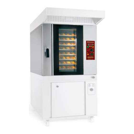
INTRODUCTION 1. INTRODUCTION The convection oven in the PLANET range has been designed to work in areas where the available space is limited. The arrangement of the pans above each other in a uniformly ventilated area ensures the space occupied is small and also the excellent cooking of the pastry and fine foods products. The control panel has controls to: 1) set the desired temperature;... -
Page 7: How To Use This Manual
HOW TO USE THIS MANUAL 2. HOW TO USE THIS MANUAL This installation use and maintenance manual must be kept near the equipment in a place where it can be readily consulted. This manual must accompany the equipment if it is transferred to another owner, as the equipment cannot be considered safe and complete without it. - Page 8 HOW TO USE THIS MANUAL Chapter 10 provides the information necessary for proper periodic and extraordinary maintenance, e.g. repairing or replacing parts of the equipment. This chapter also has an exploded view of the equipment and list of spare parts to make ordering and replacing any damaged part easier.
-
Page 9: Specifications
2006/42/CE machines directive 3.3 Proper and improper machine use The PLANET 5 and PLANET 8 cooking modules have been designed to cook fine pastries and cakes for professional use in restaurants, patisseries etc. by qualified persons only. The operations provided for in normal use are the opening and closing of the doors, loading unloading the products on the pans, switching on, adjustment, switching off and the cleaning of the equipment. -
Page 10: Technical Specifications
SPECIFICATIONS 3.4 Technical specifications The following table gives the technical specifications of the cooking modules. Unit of PLANET 5 GAS PLANET 8 GAS measurement Weight External dimensions 800x1210x775 800x1210x1055 Pans capacity (60x40) n° Production capacity (indicative) Kg/h mono-phase Electrical supply... - Page 11 SPECIFICATIONS ” Pipe Ø Consumption Max. burner power 11.5 G20 capacity – 20 mbar G25 capacity – 25 mbar G30 capacity - 28..30 mbar 1.33 Kg/h G30 capacity – 50 mbar 1.33 Kg/h Minimum burner power G20 capacity – 20 mbar G25 capacity –...
-
Page 12: Notes On Installation
NOTES ON INSTALLATION 4. NOTES ON INSTALLATION WARNING! These installation instructions are for the exclusive use of qualified personnel installing and maintaining electrical and/or gas equipment. Installation by other non qualified staff may cause damage to the equipment, persons, animals or things. Where installation of the equipment requires modifications to or additions to the building's electrical plant, the persons carrying out such changes must have their work certified to show it has been done in accordance with the norms in force in the country in which the equipment... -
Page 13: Electrical Connection
NOTES ON INSTALLATION indicated in its characteristics (see 3.). Exceeding the maximum temperature or relative humidity in particular may easily and unpredictably cause a breakdown or damage the electrical equipment and create a dangerous situation. 4.3 Electrical connection Zanolli equipment is supplied with electrical connection cable with an earth wire. In observance of the safety regulations currently in force it is compulsory to connect the earth wire (yellow-green) to an equipotential system whose effectiveness must be properly checked in accordance with the regulations in force. -
Page 14: Installation
Avoid obstructing the cooling openings on the module's right side (Fig 5.1). When choosing the place to install the cooking modules PLANET 5 and PLANET 8 take account of the fact that they can be completed by other modules in the series (hood, proofer, etc.). -
Page 15: Assembly Of The Modules
Position the modules one above the other in the right order (from the bottom: proofer or base, cooing module, hood) and fix them by means of the hooks and screws provided. MODEL A mm PLANET 5 PLANET 8 1055 steam outlet steam outlet Fig.5.3. Input position of the electric cable, steam outlet and plate. -
Page 16: Installation Of Units With Exhaust Type "A" With Power Lower Than 14 Kw
INSTALLATION 5.7 Installation of units with exhaust type “A” with power lower than 14 kW To install units type “A”, it is necessary to comply with the following requirements for room ventilation and exhaust of products of combustion. The room where the appliance is to be installed must have at least two openings, made directly in the wall and directly connected to the outside (one for suction of combustion air, and the other for the exhaust of burnt gas). -
Page 17: Check Before Start Up Electromechanical Version
INSTALLATION 5.10 Check before start up electromechanical version Switch on the main switch on the electrical panel. Switch on the switch (6.2.1.), set a temperature over 200°C. (6.3.2), position the power regulator at 10 (6.5.1.) and switch the switch on (6.2.2.). -
Page 18: Running Electromechanical Version
RUNNING ELECTROMECHANICAL VERSION 6. RUNNING ELECTROMECHANICAL VERSION 6.1 The controls Fig. 6.1. shows all the controls on the control panel: Temperature control (vers. TERM0012) Chamber temperature display Set button Push-button of ESC Up button Down button Out indicator Temperature control (vers. TERM0060) Baking chamber temperature display Push-button set and ESC Up button... -
Page 19: General
RUNNING ELECTROMECHANICAL VERSION Timer Manual timer For the controls described below refer to Fig. 6.1. 6.2 General 6.2.1 Main luminous switch 0/1 When this switch is at 0, all the panel indicators are off. When it is at 1, the switch itself and the thermo regulator light up so the temperature can be programmed. -
Page 20: Button Of Set And Of Esc (Vers. Term0060)
RUNNING ELECTROMECHANICAL VERSION WARNING! Do not keep the button pressed in, as it may change the parameters inside the thermo regulator and possibly cause unpredictable malfunctions. In this way of working the display shows the programmed temperature that can be changed using the buttons . -
Page 21: Out1" Display Led Green (Vers. Term0060)
RUNNING ELECTROMECHANICAL VERSION 6.3.6 "out1" display led green (vers. TERM0060) The "out1" display led green turns on every time the baking chamber temperature is below the set temperature. It turns off when the cooking chamber temperature reaches the set temperature and goes on again when the baking chamber temperature goes 1° C below the set temperature. -
Page 22: Accidental Flame-Out
RUNNING ELECTROMECHANICAL VERSION If the power regulator is set at 50, the flame will be set to the minimum. If the power regulator is set at 55, the flame will be at the maximum power for 3 seconds and at the minimum for 27 seconds (as long as the indicator is on). -
Page 23: Delivery Of Steam Dosages
RUNNING ELECTROMECHANICAL VERSION 6.7.2 Delivery of steam dosages By pressing one of the keys the previously programmed steam delivery can be put into effect. The delivery solenoid switches on, as does the LED on the membrane push-button panel, this time continuously. The selected dosage will stop when it has reached the number of impulses previously programmed, or can be stopped at any time by pressing one of the keys. -
Page 24: Running Electronic Version
RUNNING ELECTRONIC VERSION 7. RUNNING ELECTRONIC VERSION 7.1 The controls Fig. 7.1 shows all the controls on the control panel:: Display display chamber temperature and setting temperature Timer cooking Key selection function or power humidification / led humidification Display display power / humidification Key entry phase programming / number selection phase of the programme Display display number programme / number... -
Page 25: States Functional System
RUNNING ELECTRONIC VERSION Knob increase decrease programmable data / key data confirms programmable 7.2 States functional system 7.2.1 Member of activity and inactivity on/off general In the state of inactivity the card is fed, but none of the functions envisaged in the operation of the system will be empowered since it is not yet enabled general contactor and will appear on the display control panel with the words "OFF". -
Page 26: Setting The Timer
RUNNING ELECTRONIC VERSION Use the knob to increase (clockwise) and decrease (CCW) the value on the room temperature setting a step units. Once you reach the desired value press the knob to enter the data in memory. The parameter is displayed in fixed mode and starts flashing the display on the kitchen timer for 10 seconds, which terminated the parameter displays mode fixed and the system shows in the state of activity. -
Page 27: Function Setting Humidification Of A Programme Of Cooking
RUNNING ELECTRONIC VERSION the knob to enter the data in memory. The parameter is displayed in the way fixed and the system shows in the state of activity ready to start the cooking cycle. power heating heating heating 5 seconds 40 seconds 10 seconds 35 seconds... -
Page 28: Button Start/Stop
RUNNING ELECTRONIC VERSION Subsequently, the programming moves to stage H2. Repeat if necessary, the procedure for subsequent phases humidification H2 and H3. N.B. Programming the value of any of the stages H1-H2-H3 = 0 (phases of the programme cooking), dampness is not carried out. At the end of humidification program, a LED will show that at least during one of three phases of a program the humidification was performed. - Page 29 RUNNING ELECTRONIC VERSION - Set up to a maximum of three phases - Activate or not the function humidification For each phase, you can: - Set a different heating power - Set a different temperature - Set a different cooking time - Activate or not the function humidification Starting from the state of activity card (pressing A) select through the keys...
-
Page 30: Programming Cycle Of Pre-Heating
RUNNING ELECTRONIC VERSION press the knob to enter the data in memory. The parameter is displayed in the way fixed and the system shows in the state of activity ready to start the cooking cycle. To proceed the approach of another phase of the same program repeat steps B) to F). IMPORTANT: Setting up a program can only be done on the state of the card. -
Page 31: Alarm
RUNNING ELECTRONIC VERSION 7.6 Alarm 7.6.1 Alarm over-temperature / probe uneven If, for a failure the internal temperature of the room were more than 500 ° C (probe interrupted) or be too low (probe short-circuited), the system blocks with immediate effect the cycle underway. -
Page 32: Use
8. USE 8.1 Preparation for use If the equipment has just been installed or if it has been idle for several days, before using it to work with food products it must be completely cleaned in accordance with the procedure in chapter 8, to eliminate manufacturing residues, accumulations of dust or other substances that could contaminate the food products. -
Page 33: Loading The Oven
During cooking, you can: -- Reset the parameters relating to the selected program -- Turn on and off the room light -- Open and close the valve exhaust fumes -- Interrupt the cycle through the key During the cooking is NOT possible: -- Do not change the number of the program. -
Page 34: Switching Off
3) Keeping the steam discharge valve fully closed the products stay more humid while it is completely opened they tend to dry out and the oven performs less efficiently. It is therefore advisable to find the right balance for the valve opening. 8.8 Switching off At the end of every working day for the electromechanical version switch off the main luminous 0/1 switch... -
Page 35: Cleaning
CLEANING 9. CLEANING Cleaning needs to be carried out with the equipment switched off and at ambient temperature, after having first switched off the electrical supply with the switch on the electrical panel. 9.1 Cleaning of any parts open to view The glass is particularly sensible to quick temperature changes and may shatter. -
Page 36: Maintenance
MAINTENANCE 10. MAINTENANCE WARNING: These maintenance instructions are for the exclusive use of qualified personnel installing maintaining electrical equipment. Maintenance by other non qualified staff may cause damage to the equipment, persons, animals or things. To carry out repairs and checks it is necessary, in most cases, to remove fixed guards. -
Page 37: Fault Signals
Vac 1-N 50/60 Hz version, while Fig. 10-2 shows the wiring diagram for the electromechanical version of the Planet 8 GAS at 230 Vac 1-N 50/60 Hz version. Fig.10-3 shows the wiring diagram for the electronic version of the Planet 5 GAS at 230 Vac 1-N 50/60 Hz version, while Fig. - Page 38 MAINTENANCE Figure 10-1 Electrical diagram for Planet 5 GAS at 230 Vac. 1-N 50/60 Hz (electromechanical version).
- Page 39 MAINTENANCE Figure 10-2 Electrical diagram for Planet 8 GAS at 230 Vac. 1-N 50/60 Hz (electromechanical version).
- Page 40 MAINTENANCE Figure 10-3 Electrical diagram for Planet 5 GAS at 230 Vac. 1-N 50/60 Hz (electronic version).
- Page 41 MAINTENANCE Figure 10-4 Electrical diagram for Planet 8 GAS at 230 Vac. 1-N 50/60 Hz (electronic version).
-
Page 42: Converting To Different Types Of Gas
MAINTENANCE 10.4 Converting to different types of gas Important! To convert the unit to use with a different type of gas than the one indicated on the initial settings label, three operations must be performed: 1. The burner jets must be changed. 2. -
Page 43: Applying A New Label
MAINTENANCE For the electromechanical version switch the button in position 1. Set temperature to 200 °C and press the button. When the burner is on and flame intensity at maximum, check that the pressure indicated on the manometer connected to point A corresponds to the supply pressure envisaged for the adjustment being made. - Page 44 MAINTENANCE LIST OF SPARE PARTS N° DESCRIPTION CODES CODES Planet 5 GAS Planet 8 GAS Back panel FIAN0240 FIAN0219 Fan motor 50Hz MOTO0034 MOTO0034 Fan motor 60Hz MOTO0043 MOTO0043 Burner BGAS0019 BGAS0019 Nozzle Left side panel FIAN0239 FIAN0218 Right side panel...
- Page 45 MAINTENANCE Figure 10-5 Exploded view.
- Page 46 MAINTENANCE LIST OF ELECTRICAL PARTS ELECTROMECHANICAL VERSION N° DESCRIPTION CODES CODES Planet 5 GAS Planet 8 GAS ELET0001 ELET0001 Micro-switch for exhaust valve Micro-switch for door ELET0327 ELET0327 safety thermostat 500° C TERM0005 TERM0005 Timer ELET0062 ELET0062 MANI0021 MANI0021 Handle...
- Page 47 MAINTENANCE Figure 10-6 Exploded view of electrical parts (electromechanical version).
- Page 48 MAINTENANCE LIST OF ELECTRICAL PARTS ELECTRONIC VERSION N° DESCRIPTION CODES CODES Planet 5 gas Planet 8 gas ELET0327 ELET0327 Micro-switch for door safety thermostat 500° C TERM0005 TERM0005 ELET0451 ELET0451 Relè board ELET0428 ELET0428 Encoder Encoder handle MANI0081 MANI0081 Membrane adhesive...
- Page 49 MAINTENANCE Figure 10-7 Exploded view of electrical parts (electronic version).
-
Page 50: Decommissioning And Demolition Of The Equipment
DECOMMISSIONING AND DEMOLITION 11. DECOMMISSIONING AND DEMOLITION OF THE EQUIPMENT Before proceeding with the decommissioning disconnect the electrical supply and any other connections and then move the modules using suitable means, such as: fork-lift trucks, hoists etc., keeping in mind at all times the position of the centre of gravity (table 5.2) indicated in the chapter INSTALLATION (5). -
Page 51: Declaration Of Conformity
DECLARATION OF CONFORMITY 12. DECLARATION OF CONFORMITY...
Need help?
Do you have a question about the PLANET 8 and is the answer not in the manual?
Questions and answers