Table of Contents
Advertisement
Quick Links
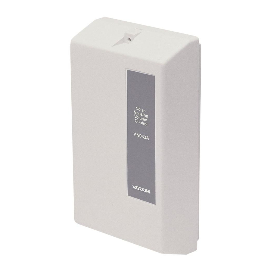
NOISE SENSING VOLUME CONTROL
GENERAL
The V-9933A is designed to electronically adjust the
level of a page by monitoring ambient noise levels in
an area of a building.
SPECIFICATIONS
Purpose
The V-9933A provides automatic paging level
adjustments in areas where ambient noise levels are
continuously changing.
Application
Valcom one-way paging systems
Features
Solid-state design
Low power requirements
Self-contained or optional remote sensing device
Capacity
Each V-9933A will control the audio for up to 150
Valcom one-way amplified speaker assemblies in a
single zone. Multiple V-9933A units can be used
within the same zone.
Additional Materials Required
At the time of installation, the installer should provide
the following materials:
24VDC power supply (If existing supply is
inadequate)
Optional V-9934, Remote Sensing Device (Up to 4
units)
Dimensions/Weight
The V-9933A is designed to be wall mounted.
7.30" H x 4.50" W x 2.00" D
(18.54cm H x 11.43cm W x 5.08cm D)
0.9 lbs. (.41kg)
Power Requirements
Power Requirement:
-24VDC Filtered Battery
Operating Current:
Nominal Specifications
V-9933A
Automatic Level Adjustment Range:
Power Output:
Frequency Response:
Input Impedance:
Output Impedance:
Operating Temperature:
Power Requirements:
Monitor Reset:
OPERATION
The V-9933A, Noise Sensing Volume Control,
continuously monitors the surrounding area noise by
utilizing a built-in or optional remote microphone.
When a page is made, the V-9933A electronically locks
onto the last area noise sample. A -23dBm signal or
higher is required on the input before the
V-9933A will activate and lock.
Once activated, the amplifier is automatically set to the
proper gain level for the amount of background noise.
The amplifier will remain locked at that gain level for
the duration of the page.
After the page is made, there is a five (5) second delay
before the V-9933A starts monitoring the area noise
levels. Refer to Figure 3 for a simplified schematic of
the V-9933A.
INSTALLATION
150mA
These instructions cover only the installation
procedure of the Valcom V-9933A. Please consult
1
Issue 2
See Chart 1
-10dBm
50-12kHz +3dB
25k Ohms
8 Ohms
0 to +50 degrees C
-24VDC signal battery
5 seconds
947933
Advertisement
Table of Contents

Related Manuals for Valcom V-9933A


Summary of Contents for Valcom V-9933A
- Page 1 Low power requirements Self-contained or optional remote sensing device Capacity Each V-9933A will control the audio for up to 150 Valcom one-way amplified speaker assemblies in a single zone. Multiple V-9933A units can be used within the same zone. Additional Materials Required...
- Page 2 Call (540) 563-2000 and ask for Technical Support, or call (540) 767-1555 for Valcom 24-hour Faxback System or visit our website at http://www.valcom.com. The V-9933A is not field repairable. Valcom equipment contains no user serviceable parts inside.
- Page 3 *Use lineman's test set (monitor setting) to check for audio. Valcom, Inc. warrants its products to be free from defects in materials and workmanship under conditions of normal use and service for a period of one year from the date of shipment. The obligation under this warranty shall be limited to the replacement, repair or refund of any such defective device within the warranty period, provided that: inspection by Valcom, Inc.
- Page 4 V-9933A NOISE SENSING VOLUME CONTROL DIP SWITCH SETTINGS INTERNAL MIC ON SETTING ADJUSTMENT RANGE 2 OFF 3 ON = 30dB 2 OFF 3 OFF = 60dB 2 ON 3 OFF = 45dB SETUP CHART 1 Microprocessor Binary code displayed by LEDs will change with change in ambient noise.
- Page 5 Zone Valcom Telephone Page System Control Audio Unit Figure 2 - Simplified Block Diagram of Connections MICROPHONE GAIN CONTROL MICROPHONE INPUT -24VDC SIMPLIFIED SCHEMATIC EXT MIC IN V-9933A -24V Power Supply One-Way Speaker Assemblies LEVEL SENSE CONTROL CIRCUIT CIRCUIT PAGE SENSE...
Need help?
Do you have a question about the V-9933A and is the answer not in the manual?
Questions and answers