
Related Manuals for Shinhoo GPA-IV Series


Summary of Contents for Shinhoo GPA-IV Series
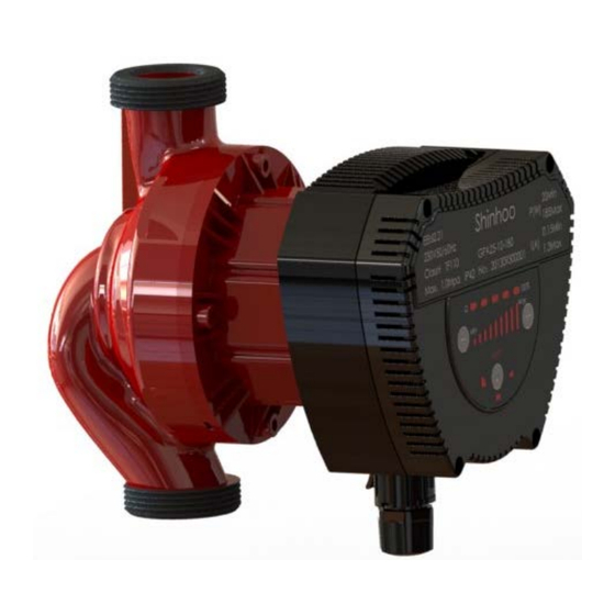
- Page 1 GPA-Ⅳ Series Energy-saving Pipeline Canned Motor Pump Installation and Operation Manual Hefei Xinhu Canned Motor Pump Co., Ltd...
- Page 2 Notes: 1. Read the installation manual carefully before installation and use. 2. The manufacturer will not be liable for any personal injury, pump damage and other property damage due to failure to comply with contents specified in safety warning signs. 3.
- Page 3 take an isolation measures to avoid access of children. 21. This product shall be stored in a dry, well ventilated and cool place under room temperature. Warning ! Before installation, you must carefully read the installation and operation manual. The installation and use of the equipment must comply with local regulation and applicable operation standards.
-
Page 4: Operating Conditions
·stable and variable-flow heat supply system ·variable-temperature pipeline heat supply system ·heat supply system with night mode ·HVAC system ·industrial circulation system ·domestic heating and domestic water supply system This pump is equipped with permanent-magnet motor and differential pressure controller, capable of automatically & continuously adjusting motor performance to meet the actual needs of system. -
Page 5: Relative Humidity(Rh
Ambient temperature: 0℃~+40℃ 3.2 Relative humidity(RH): Max. humidity: 95% 3.3 Medium (liquid delivery) temperature To avoid condensation in control box and the stator, the temperature of liquid pumped by the motor pump must be always higher than ambient temperature. 3.4 System Pressure Maximum pressure 1.0Mpa(10bar). -
Page 6: Installation
4. Installation 4.1 Installation ·When installing GPA series circulating pump, the arrow on motor pump case indicates the flow direction of liquid through the pump. ·When installing the motor pump in the pipeline, two supplied gaskets must be installed at the inlet and outlet. ·During the installation, the shaft of motor pump must be horizontal. - Page 7 4.2 Position of Junction Box Changing Position of Junction Box 45°。 junction box can be rotated in a step of The procedure for changing the position of junction box are as follows: 1.Close the valves at the inlet and outlet and release the pressure; 2.screw and remove the four socket head screws that fasten the pump body;...
- Page 8 Warning ! Pumping liquid may be high-temperature and high-pressure; therefore, the liquid in the system must be completely drained or the valves on both sides of motor pump must be closed before removing the socket head screws. Caution When changing the position of junction box, the motor pump can be started only after the system is filled with pumping liquid or the valves on both sides of motor pump are opened.
-
Page 9: Electrical Connection
5. Electrical Connection... -
Page 11: Control Panel
Electrical connection and protection shall comply with local codes and norms. Warning ! The motor pump must be earthed The motor pump must be connected to an external power switch, and the minimum space between all the electrodes is 3mm. ·GPA Ⅳseries circulating motor pump needs no protection from external motor. - Page 12 The lighted area showing the four modes of operation of the motor pump. The setting button for the motor pump operation mode. The button to increase gear. The lighted area showing the gear. 6.2 The showing position of fault code Fault Code Fault Description Gear light 1 flashing...
- Page 13 Button Count Light Area Descriptions AUTO Self- adaptive BL(1-9) (Proportional Proportional pressure curve pressure) HD(1-9)(Constant Constant pressure curve pressure) HS(1-9)(Constant Constant speed curve speed) 6.4 Button for selecting motor pump settings By pressing the button once at 2 seconds interval, the motor pump setting mode will change once.
- Page 14 System Type Motor Pump Setting Position Recommended Options Underfloor AUTO HD(1-9) heating system. Dual line AUTO BL(1-9) heating system. Single line BL(1-9) heating system. ·AUTO (Self Adaptive Mode) mode can adjust the performance of motor pump based on the actual heat demand of the system. As the performance is adjusted gradually, it is suggested, before changing motor pump setting, to maintain AUTO (Automatically Adaptive Mode) mode setting for at least one week.
- Page 15 Constant Pressure Control In this control mode, the differential pressure of both ends of the motor pump remains constant and is irrelevant to the flow rate. In the Q/H Figure, constant pressure curve is a horizontal performance curve represented with HD1(1-9).
- Page 16 Duty Cycle Input High Voltage Input Low Voltage Input Current Note “Signal Ref”is a reference grounded, and it is not connected to protective grounded. Interface The pump is controlled by external electrical elements and components through interfaces. The interfaces convert external signals into signals that can be recognized by microprocessor in the pump.
- Page 17 ● When PWM input signal is 0% or 100%, the pump will switch to non-PWM mode (normal mode), and the default system will have no PWM signal input. PWM input signal(%) Pump operation status Pump switches to non-PWM mode and system acquiesces there is no PWM signal input.
- Page 18 Stand-by The pump stops The pump does not work and will Pump stops caused by alarm. restart only after trouble is Malfunctions (pump blocked). addressed. Pump stops caused by alarm, Pump does not work and will restart electrical malfunction.
- Page 19 input signal (V) Pump status U<1V The pump stops The pump runs at the lowest speed (when the analog voltage signal changes from large to small, when the voltage value is less than 1V, the pump stops; >1V, the pump runs at the minimum 1V<U<3V speed.
- Page 20 第 7 章 Bypass valve The purpose of bypass valve: when all the valves and/or temperature-sensing valves of heat radiator in the floor heating loop are closed, it can ensure that the heat from boiler can be distributed. Elements in the system: ●...
- Page 21 8.3 Automatic Bypass Valve (temperature-sensing type) Follow the following procedures: 1.The pump should be set in HS1(constant gear 1 mode) when the bypass valve is adjusted. The minimum flow rate(Q min) of the system shall be always guaranteed. Please refer to bypass valve manual provided by the manufacturer. 2、After the regulating of bypass valve completes, set the pump to lowest or highest constant pressure mode.
- Page 22 motor pump in accordance with the manual. Please refer to Chapter 7. Motor pump cannot run in idle speed without pumping liquid. Caution 9.3 Vent the heating system 10.Motor Pump Setting and Performance 10.1 Relations between Motor Pump Setting and Performance...
-
Page 23: Performance Curve
11. Performance Curve 11.1 Guide on Performance Curve Every setting of the motor pump has corresponding performance curve (Q/H curve). However AUTO (Self Adaptive Mode) mode covers just one performance scope. Setting Pump Characteristics Curve Functions AUTO function will automatically control the pump performance within the specified scope. - Page 24 11.2 Curve conditions The followings are applicable to the performance curve specified in the GPA series manual: ·Test liquid: air-free water. ·Applicable density of curve ρ=983.2 kg/m3, and liquid temperature +60 ℃ . · All curves represent averaged value, and shall not be used as guarantee curve.
- Page 25 GPAXX-8 Ⅳ Constant Speed and Auto Mode Performance Curve GPAXX-10 Ⅳ Constant Speed and Auto Mode Performance Curve...
- Page 26 · Constant pressure mode performance curve GPAXX-6 Ⅳ Constant Pressure Mode Performance Curve GPAXX-8 Ⅳ Constant Pressure Mode Performance Curve...
- Page 27 GPAXX-10 Ⅳ Constant Pressure Mode Performance Curve ·Proportional pressure mode performance curve GPAXX-6 Ⅳ Proportional Pressure Mode Performance Curve...
- Page 28 GPAXX-8 Ⅳ Proportional Pressure Mode Performance Curve GPAXX-10 Ⅳ Proportional Pressure Mode Performance Curve...
- Page 29 12. Features 12.1 Nameplate Instructions 序号 Descriptions Manufacturer Name Product Model Minimum mode minimum input Power power P1 (Watt) Maximum mode maximum input power P1 Minimum mode minimum current Current (Amp) Maximum mode maximum current Maximum system load bearing (Mpa) Digit 1 to digit 6 indicates Date manufacturing date...
- Page 30 Insulation class Degree of protection Temperature class Authentication mark 12.2 Model Instructions the model of motor pump is composed of capitalized Latin letters and Arabic numbers, which means:...
-
Page 31: Technical Parameters
13. Technical Parameters and Installation Dimensions 13.1 Technical Parameters 1×(220~240)V +6%/-10%,50/60Hz Power Supply Voltage Motor Protection the pump needs no external protection Degree of Protection IP42 Insulation Class Relative Humidity(RH) Max. 95% System Load Bearing 1.0 MPa Liquid Temperature Minimum Inlet Pressure ≤+85℃... -
Page 32: Installation Dimensions
13.2 Installation Dimensions Power Dimension(mm) Product Model (W) GPA25-10 Ⅳ 11/2" GPA32-10 Ⅳ 2"... -
Page 33: Troubleshooting Schedule
14. Trouble-Shooting Schedule ! Warning Before conducting any maintenance and repair of the motor pump, ensure that power supply has been cut off and will not be connected accidentally. Symptom Control Panel Corrective Action Equipment fuse burned Replace the fuse the circuit breaker of current control connect the circuit or voltage control opens... - Page 34 Hefei Xinhu Product Warranty Hefei Xinhu Canned Motor Pump Co., Ltd offers 12 months of quality warranty for its products since the date of sales, and is responsible for product malfunctions or damaged due to manufacturing and material defects. This warranty is valid only when the product is installed strictly in accordance with Xinhu Installation and Operation Manual and certified operation practices.
- Page 35 conditions, war, riot, wind (rain) storm, disaster or other force majeure. Hefei Xinhu Canned Motor Pump Co., Ltd reserves the right to interpret any matters unmentioned in this product warranty.
Need help?
Do you have a question about the GPA-IV Series and is the answer not in the manual?
Questions and answers